US5456297A - Detergent dispenser with filling mechanism - Google Patents
Detergent dispenser with filling mechanism Download PDFInfo
- Publication number
- US5456297A US5456297A US08/042,802 US4280293A US5456297A US 5456297 A US5456297 A US 5456297A US 4280293 A US4280293 A US 4280293A US 5456297 A US5456297 A US 5456297A
- Authority
- US
- United States
- Prior art keywords
- container
- support
- neck
- dispenser
- dispenser according
- Prior art date
- Legal status (The legal status is an assumption and is not a legal conclusion. Google has not performed a legal analysis and makes no representation as to the accuracy of the status listed.)
- Expired - Fee Related
Links
- 239000003599 detergent Substances 0.000 title abstract description 3
- 239000007788 liquid Substances 0.000 claims abstract description 24
- XLYOFNOQVPJJNP-UHFFFAOYSA-N water Substances O XLYOFNOQVPJJNP-UHFFFAOYSA-N 0.000 description 7
- 239000000126 substance Substances 0.000 description 3
- 238000004140 cleaning Methods 0.000 description 2
- 230000000694 effects Effects 0.000 description 1
- 230000003287 optical effect Effects 0.000 description 1
- 238000011012 sanitization Methods 0.000 description 1
Images


Classifications
-
- B—PERFORMING OPERATIONS; TRANSPORTING
- B67—OPENING, CLOSING OR CLEANING BOTTLES, JARS OR SIMILAR CONTAINERS; LIQUID HANDLING
- B67D—DISPENSING, DELIVERING OR TRANSFERRING LIQUIDS, NOT OTHERWISE PROVIDED FOR
- B67D1/00—Apparatus or devices for dispensing beverages on draught
- B67D1/08—Details
- B67D1/12—Flow or pressure control devices or systems, e.g. valves, gas pressure control, level control in storage containers
- B67D1/1202—Flow control, e.g. for controlling total amount or mixture ratio of liquids to be dispensed
- B67D1/1234—Flow control, e.g. for controlling total amount or mixture ratio of liquids to be dispensed to determine the total amount
- B67D1/124—Flow control, e.g. for controlling total amount or mixture ratio of liquids to be dispensed to determine the total amount the flow being started or stopped by means actuated by the vessel to be filled, e.g. by switches, weighing
-
- B—PERFORMING OPERATIONS; TRANSPORTING
- B65—CONVEYING; PACKING; STORING; HANDLING THIN OR FILAMENTARY MATERIAL
- B65D—CONTAINERS FOR STORAGE OR TRANSPORT OF ARTICLES OR MATERIALS, e.g. BAGS, BARRELS, BOTTLES, BOXES, CANS, CARTONS, CRATES, DRUMS, JARS, TANKS, HOPPERS, FORWARDING CONTAINERS; ACCESSORIES, CLOSURES, OR FITTINGS THEREFOR; PACKAGING ELEMENTS; PACKAGES
- B65D1/00—Containers having bodies formed in one piece, e.g. by casting metallic material, by moulding plastics, by blowing vitreous material, by throwing ceramic material, by moulding pulped fibrous material, by deep-drawing operations performed on sheet material
- B65D1/02—Bottles or similar containers with necks or like restricted apertures, designed for pouring contents
- B65D1/0223—Bottles or similar containers with necks or like restricted apertures, designed for pouring contents characterised by shape
-
- B—PERFORMING OPERATIONS; TRANSPORTING
- B65—CONVEYING; PACKING; STORING; HANDLING THIN OR FILAMENTARY MATERIAL
- B65D—CONTAINERS FOR STORAGE OR TRANSPORT OF ARTICLES OR MATERIALS, e.g. BAGS, BARRELS, BOTTLES, BOXES, CANS, CARTONS, CRATES, DRUMS, JARS, TANKS, HOPPERS, FORWARDING CONTAINERS; ACCESSORIES, CLOSURES, OR FITTINGS THEREFOR; PACKAGING ELEMENTS; PACKAGES
- B65D23/00—Details of bottles or jars not otherwise provided for
- B65D23/10—Handles
- B65D23/102—Gripping means formed in the walls, e.g. roughening, cavities, projections
-
- B—PERFORMING OPERATIONS; TRANSPORTING
- B67—OPENING, CLOSING OR CLEANING BOTTLES, JARS OR SIMILAR CONTAINERS; LIQUID HANDLING
- B67D—DISPENSING, DELIVERING OR TRANSFERRING LIQUIDS, NOT OTHERWISE PROVIDED FOR
- B67D7/00—Apparatus or devices for transferring liquids from bulk storage containers or reservoirs into vehicles or into portable containers, e.g. for retail sale purposes
- B67D7/06—Details or accessories
- B67D7/32—Arrangements of safety or warning devices; Means for preventing unauthorised delivery of liquid
- B67D7/34—Means for preventing unauthorised delivery of liquid
- B67D7/344—Means for preventing unauthorised delivery of liquid by checking a correct coupling or coded information
-
- B—PERFORMING OPERATIONS; TRANSPORTING
- B67—OPENING, CLOSING OR CLEANING BOTTLES, JARS OR SIMILAR CONTAINERS; LIQUID HANDLING
- B67D—DISPENSING, DELIVERING OR TRANSFERRING LIQUIDS, NOT OTHERWISE PROVIDED FOR
- B67D2210/00—Indexing scheme relating to aspects and details of apparatus or devices for dispensing beverages on draught or for controlling flow of liquids under gravity from storage containers for dispensing purposes
- B67D2210/00028—Constructional details
- B67D2210/00065—Constructional details related to the use of drinking cups or glasses
-
- Y—GENERAL TAGGING OF NEW TECHNOLOGICAL DEVELOPMENTS; GENERAL TAGGING OF CROSS-SECTIONAL TECHNOLOGIES SPANNING OVER SEVERAL SECTIONS OF THE IPC; TECHNICAL SUBJECTS COVERED BY FORMER USPC CROSS-REFERENCE ART COLLECTIONS [XRACs] AND DIGESTS
- Y10—TECHNICAL SUBJECTS COVERED BY FORMER USPC
- Y10S—TECHNICAL SUBJECTS COVERED BY FORMER USPC CROSS-REFERENCE ART COLLECTIONS [XRACs] AND DIGESTS
- Y10S141/00—Fluent material handling, with receiver or receiver coacting means
- Y10S141/01—Magnetic
Definitions
- the invention relates to a dispenser for dispensing detergents and other cleaning liquids, for example.
- the present invention in its different aspects, is aimed at overcoming or ameliorating one or both, of the above-described problems.
- the invention provides a dispenser for filling a container with a liquid, comprising: a support for the container to be filled; a source of liquid; switch means controlling the flow of liquid into the container; and resilient means urging the said support in an upwards direction; wherein the switch means is operated by the container 2 on the support, whereby the switch is activated by the empty container being urged upwards by the resilient means and deactivated when the weight of the filled container overcomes the force of the resilient means.
- the support can be a platform on top of which the container sits, but it is preferably a cradle which holds the container by its upper portion--for example its neck with the major part of the container depending from the cradle.
- This latter arrangement has the advantage that different size bottles can be filled from the same dispenser without adjustment, unlike the former arrangement in which the distance between the source of liquid and the platform defines the height of the container to be filled so that the platform position needs to be changed for use with different containers.
- the cradle is preferably pivoted about a substantially horizontal axis.
- This embodiment has the advantage of relative simplicity, with the empty container being mounted by simply pulling down the pivoting cradle, against the action of a spring force, slotting in the container and letting it go. As the container is filled, its weight forces the cradle down again until it is at a position when the source of liquid is turned off. The full container is then removed.
- the container it is advantageous for the container to slot into the cradle, with parts on the container and the cradle inter-engaging so that the container is suspended from the cradle.
- the container and cradle have corresponding pins and recesses so that only a container with the correct pins or recesses can be fitted onto the dispenser for filling. This arrangement avoids the possibility of the wrong liquid being filled into a given container from a dispenser.
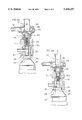
- FIG. 1 is a schematic elevational view of a dispenser according to the invention
- FIGS. 2 and 3 are detail views of FIG. 1 showing the operative connection between the dispenser and containers of two different sizes;
- FIGS. 4A and 4B are detail views of the switch means in the off and on positions, respectively;
- FIG. 5 is a perspective view illustrating the connection between a first container and the support in the dispenser of FIG. 1;
- FIG. 6 is a perspective view of a second container for use with the dispenser of FIG. 1;
- FIG. 7 is a schematic elevational view of a second embodiment of a dispenser according to the invention.
- FIG. 8 is a detail view of FIG. 7 showing the operative connection between the dispenser and the container.
- the dispenser shown in FIG. 1 comprises a support 1 for a container 2 to be filled by liquid through a dispensing head 3.
- the support 1 carries the weight of the container with the assistance of the action of a spring 4.
- the support 1 is pivoted about horizontal axis 5.
- the support or cradle 1 is lowered manually, against the action of the spring 4, and the container 2 is fitted on the support 1.
- the force of the spring 4 urges the neck of the container into the dispensing head 3. This action, described in more detail below, moves magnet 7 upwards.
- Water from a source can therefore pass along pipe 8, through valve 9, through the backflow preventer 10 and to the venturi 11 where it entrains concentrated chemical fed through pipe 12 in a conventional manner.
- the diluted liquid is then filled into the container 2 through the dispensing head 3.
- the filled container 2 is then manually released from the support 1, which is pulled back up by the spring 4 but in the absence of another container does not actuate the valve 9.
- FIG. 1 Also seen in FIG. 1 is a drip container 14 and a slidable drip tray 15, which is urged towards the container position by means of a spring 16.
- the cradle 1 is shown to be pivotally mounted, but this is not essential.
- the support 1 could alternatively be mounted for vertical movement against a spring force without a pivotal mounting.
- FIGS. 2 and 3 show schematically the operable connection between the container 2 and the dispensing head 3.
- FIG. 2 shows the connection for a relatively large diameter neck container and
- FIG. 3 shows the connection for a smaller diameter neck container.
- the dispensing head 3 consists of two fixed concentric tubular members 20, 21, the liquid being supplied to inner tubular member 20 for filling of the container 2.
- An annular member 22 is slidably mounted between the tubular members 20, 21.
- the tubular member 20 is formed with flange 20A around its bottom edge.
- the purpose of this is to prevent the wrong containers, in particular containers with a neck of smaller diameter, being filled. It will be understood that the flange 20A will not fit inside a container neck whose inner diameter is less than that of the flange. Thus, such a container neck cannot contact the annular member 22 to move it upwards and actuate the switch.
- FIG. 3 the filling of the wrong containers--here containers of a larger diameter neck--is prevented by means of a ring 25 fitted on the bottom of tubular member 21.
- the ring 25 has a smaller inner diameter than the member 21 so that containers with an outer neck diameter above a certain size cannot contact the annular member 22.
- a depending wing 26 is fitted at one point around the ring 25. This slots into a corresponding recess 27 in the shoulder of the container 2. Thus, containers without this special recess will not be able to contact the annular member 22, even if their neck diameter is less than the inner diameter of the ring 25.
- FIGS. 4A and 4B The opening and closing of the valve 9 is shown in FIGS. 4A and 4B.
- FIG. 4A shows the container 2 in a position free of the filling head, i.e. the position it is in when it is empty and before the support 1 is released or the position it is in when it is full.
- FIG. 4B shows the container 2 in a position contacting the filling head, i.e., the position it is in when being filled.
- FIGS. 4A and 4B show the filling of the smaller neck container of FIG. 3, but it will be understood that the larger neck container of FIG. 2 is filled in the same manner.
- Valve 9 comprises valve body 91 including an inlet 92 for water along pipe 8, an outlet 93 and valve stem 94.
- Valve spring 13 is fitted around the valve stem 94, and is contacted by the magnet 7 which in turn is contacted by the annular member 22.
- the outlet 94 is closed by valve disc 95 mounted on a flexible diaphragm 96.
- the valve disc 95 has a central opening 97 connecting to the outlet 94 and a lateral opening 98 which admits water from the inlet 92.
- the central opening 97 is closed by a core member 99 which is urged upwardly by a weak core spring 100.
- the disc 95 is forced against the outlet 93 by the differential pressure of the water, and thus the valve 9 is shut, as seen in FIG. 4B.
- annular member 22 pushes the magnet 7 upwards to the position seen in FIG. 4B. In this position, the magnet 7 pulls the core member 99, which is magnetically attractive, away from the valve disc 95.
- FIG. 5 shows the mounting of the smaller container 2 on the support 1.
- the support is formed with a pair of forwardly extending arms 30, 30' with a slot 31 defined therebetween.
- On the inside of each arm is a shoulder 32, 32' with a recess 33, 33' at one point along its length.
- the recesses 33, 33' are formed opposite each other, across the slot 31, and each has a generally U-shape which tapers outwardly towards the top.
- Drip tray 15 is seen at the left hand side of FIG. 5.
- the drip tray is shown in a retracted position to which it would be pushed by a container 2. Without the container 2 present in the slot 31, the drip tray 15 would normally be pulled forward by the spring 16 to a position over the recesses 33, 33' i.e. beneath dispensing head 3 in order to catch drips therefrom.
- the slot 31 Underneath the drip tray 15, the slot 31 is closed and extending forwardly from the closed end of the slot is a pair of pins 34.
- the pins 34 are arranged in two of five possible positions.
- the container 2 has segmental recesses 35 on either side, below shoulder 36 (only one recess is seen in FIG. 5).
- the narrowed portion formed by recesses 35 has a width just less than the gap between the shoulders 32, 32'.
- a lug 37 depends from the top of each segmental recess 35.
- slots 38 are formed, in two of five possible positions (two alternative positions are shown in dashed lines; the third one is out of view).
- a recess 27 is formed in the shoulder 36 of the container 2, just below the neck 24.
- the support 1, is lowered and the container 2 is slotted into the support 1, along the slot 31, thereby pushing back drip tray 15.
- the pins 34 register in the slots 38 and the container 2 can then be allowed to hang on the support 1, with its lugs 37 fitting into the recesses 33, 33' on the shoulders 32, 32'.
- the support 1 is then released and the spring 4 lifts it upwards so that the neck 24 actuates the switch which controls its filling.
- the large neck container has, for example, a volume of 2 liters.
- the small neck container has, for example, a volume of 0.75 liters.
- the vertical distance between the lug 37 and the top of the neck 24 of the containers seen in FIGS. 5 and 6 is the same in each case.
- the same dispenser can be used with both containers, and indeed containers of other sizes, with the appropriate adjustment made to the filling head 3 (FIGS. 2 and 3) and to the arrangement of pins 34 (FIG. 5).
- the container 2 support is arranged differently from FIG. 1.
- the containers 2 are suspended from a support 1, but in FIG. 7 the container 2 is placed onto the support 1 which is in the form of a platform.
- the dispenser of FIG. 7 is similar and so the same numerals are used to denote corresponding parts.
- the platform 1 can be manually lowered by means of a pivoting handle 40 to allow a container 2 to be placed thereon. Release of the handle 40 allows the springs 4 to urge the bottle neck upwards into the dispensing head 3. As shown in FIG. 8, movement of the bottle neck into the dispensing head causes annular member 22 to move upwards, thereby moving magnet 7 on the valve 9. As the weight of the container 2 increases, the container 2 moves out of the dispensing head 3 and the valve 9 is turned off.
- switches can be used to control the flow of liquid through the dispensing head 3 than the type described above.
- a conventional solenoid valve 9 could be used, together with a microswitch operated by movement of the annular member.
- optical switches or proximity detectors could be used to detect the position of the container 2 and turn on or off the valve 9. The important feature of the switch means is that it is operated by the upward movement of the empty container and the opposite movement of the filled container 2.
- the coil spring 4 described in relation to the illustrated embodiments could of course be replaced by other resilient members, for example, leaf springs or elastomeric springs (rubber bands), or even pneumatic springs.
- the force urging the support 1 upwards could be obtained by means of a weight attached to a cord running over a pulley above the support, and connected to the support 1, or by means of a weight on a counter-balance arm on the opposite side to the pivot from the cradle. All means of urging the support for the container 2 upwards, allowing the support to fall as the container 2 fills, and again lifting the support 1 with another empty container, are covered by the invention as defined in the attached claims.
Landscapes
- Engineering & Computer Science (AREA)
- Mechanical Engineering (AREA)
- Ceramic Engineering (AREA)
- Filling Of Jars Or Cans And Processes For Cleaning And Sealing Jars (AREA)
- Coating Apparatus (AREA)
- Manufacture Of Switches (AREA)
- Magnetic Resonance Imaging Apparatus (AREA)
- Table Devices Or Equipment (AREA)
- Closures For Containers (AREA)
- Containers And Packaging Bodies Having A Special Means To Remove Contents (AREA)
- Glass Compositions (AREA)
- Steroid Compounds (AREA)
- Nitrogen Condensed Heterocyclic Rings (AREA)
- Devices For Dispensing Beverages (AREA)
Priority Applications (1)
| Application Number | Priority Date | Filing Date | Title |
|---|---|---|---|
| US08/475,754 US5896898A (en) | 1993-04-05 | 1995-09-18 | Dispenser |
Applications Claiming Priority (2)
| Application Number | Priority Date | Filing Date | Title |
|---|---|---|---|
| GB9207384 | 1992-04-03 | ||
| GB929207384A GB9207384D0 (en) | 1992-04-03 | 1992-04-03 | Dispenser |
Related Child Applications (1)
| Application Number | Title | Priority Date | Filing Date |
|---|---|---|---|
| US08/475,754 Division US5896898A (en) | 1993-04-05 | 1995-09-18 | Dispenser |
Publications (1)
| Publication Number | Publication Date |
|---|---|
| US5456297A true US5456297A (en) | 1995-10-10 |
Family
ID=10713447
Family Applications (1)
| Application Number | Title | Priority Date | Filing Date |
|---|---|---|---|
| US08/042,802 Expired - Fee Related US5456297A (en) | 1992-04-03 | 1993-04-05 | Detergent dispenser with filling mechanism |
Country Status (11)
| Country | Link |
|---|---|
| US (1) | US5456297A (de) |
| EP (2) | EP0675073B1 (de) |
| JP (1) | JPH0826392A (de) |
| AT (2) | ATE133144T1 (de) |
| AU (1) | AU664601B2 (de) |
| BR (1) | BR9300920A (de) |
| CA (1) | CA2092855A1 (de) |
| DE (2) | DE69314662T2 (de) |
| DK (1) | DK0564303T3 (de) |
| ES (2) | ES2108539T3 (de) |
| GB (1) | GB9207384D0 (de) |
Cited By (11)
| Publication number | Priority date | Publication date | Assignee | Title |
|---|---|---|---|---|
| US5738153A (en) * | 1995-11-03 | 1998-04-14 | E. I. Du Pont De Nemours And Company | Measuring and dispensing system for solid dry flowable materials |
| US5827486A (en) * | 1996-02-19 | 1998-10-27 | Diversey Lever, Inc. | Dispenser |
| US5908143A (en) * | 1995-12-22 | 1999-06-01 | Diversey Lever, Inc. | Single shot liquid dispenser |
| US6073667A (en) * | 1997-10-24 | 2000-06-13 | Serac Group | Weight-filling method, and a corresponding device |
| US6667444B1 (en) * | 1999-02-09 | 2003-12-23 | De Montfort Expertise Limited | Fluid container weighing apparatus which uses the fluid conduit as the weighing mechanism |
| US6688341B1 (en) * | 1999-07-23 | 2004-02-10 | Sidel | Weight-filling machine comprising a weighing station |
| US6737028B1 (en) | 1999-06-02 | 2004-05-18 | Sunburst Chemicals, Inc. | Solid cast container |
| US20080302440A1 (en) * | 2005-08-05 | 2008-12-11 | Johnsondiversey, Inc. | Dispensing Apparatus |
| US20100230004A1 (en) * | 2007-06-21 | 2010-09-16 | Akira Taniguchi | Tablet Filling Instrument |
| US20120116292A1 (en) * | 2009-05-27 | 2012-05-10 | Ino Therapeutics, Llc | Devices And Methods For Engaging Indexed Valve And Pressurized Canister Assembly With Collar And For Linear Actuation By Plunger Assembly Into Fluid Communication With Device For Regulating Drug Delivery |
| US9920884B2 (en) | 2012-02-29 | 2018-03-20 | Globalforce Ip Limited | Automated gas canister filler |
Families Citing this family (15)
| Publication number | Priority date | Publication date | Assignee | Title |
|---|---|---|---|---|
| GB9313854D0 (en) * | 1993-07-05 | 1993-08-18 | Diversey Eng Europ | Element |
| GB9322641D0 (en) * | 1993-11-03 | 1993-12-22 | Diversey Equipment Technologie | Dispenser |
| IT1273488B (it) * | 1995-02-02 | 1997-07-08 | Gen Detergents Spa | Riempitrice automatica per ri-riempire flaconi e simili |
| US5832972A (en) * | 1996-07-26 | 1998-11-10 | Ecolab Inc. | Dilution dispensing system with product lock-out |
| CH691965A5 (de) * | 1997-04-01 | 2001-12-14 | Femit Plastic Ag | Kunststoff-Flasche |
| US6196522B1 (en) * | 1999-04-02 | 2001-03-06 | Ecolab, Inc. | Geometric lockout coupler |
| US6105633A (en) * | 1999-07-02 | 2000-08-22 | Ecolab Inc. | Liquid dispenser |
| CA2440097A1 (en) | 2001-03-06 | 2002-09-12 | Johnsondiversey Inc. | Dispensing apparatus |
| EP1346945A1 (de) * | 2002-03-21 | 2003-09-24 | JohnsonDiversey, Inc. | Vorrichtung zum Abgeben von Flüssigkeiten in spezifische Behälter |
| EP1350757A1 (de) | 2002-03-27 | 2003-10-08 | JohnsonDiversey, Inc. | Durchflussdrosselvorrichtung |
| BRPI0612550A2 (pt) * | 2005-06-28 | 2012-01-03 | Fluid Fashions Pty Ltd | sistema de armazenamento de bebidas |
| JP6246107B2 (ja) * | 2014-10-24 | 2017-12-13 | イノ セラピューティクス エルエルシー | 指標付弁と襟部を有する加圧容器組立体を係合するため、かつ薬物送達を調整するための装置と流体連通したプランジャ組立体により直線的に作動させるための装置および方法 |
| US10759554B2 (en) * | 2017-02-02 | 2020-09-01 | Rai Strategic Holdings, Inc. | Dispenser unit for aerosol precursor |
| JP6618976B2 (ja) * | 2017-11-14 | 2019-12-11 | イノ セラピューティクス エルエルシー | 指標付弁と襟部を有する加圧容器組立体を係合するため、かつ薬物送達を調整するための装置と流体連通したプランジャ組立体により直線的に作動させるための装置および方法 |
| CN109335057B (zh) * | 2018-11-16 | 2020-08-04 | 薛垚楠 | 自动化饮料分装设备 |
Citations (28)
| Publication number | Priority date | Publication date | Assignee | Title |
|---|---|---|---|---|
| US532235A (en) * | 1895-01-08 | Bottle-filling apparatus | ||
| FR815490A (fr) * | 1936-03-28 | 1937-07-12 | Support de bouteilles, flacons et autres récipients pour machines à emplir | |
| US2518349A (en) * | 1947-01-10 | 1950-08-08 | Fed Mfg Co | Receptacle operated filling valve with vent cutoff |
| DE814259C (de) * | 1943-09-27 | 1951-09-20 | Ritter Company | Selbsttaetig arbeitende Fuellvorrichtung fuer Behaelter |
| US2757846A (en) * | 1953-10-16 | 1956-08-07 | Screw Machine Products Company | Liquid dispensers |
| DE1041383B (de) * | 1954-05-14 | 1958-10-16 | Ritter Co Inc | Selbsttaetige Fluessigkeits-Fuellvorrichtung |
| CA572435A (en) * | 1959-03-17 | R. Ziegler Eugene | Automatic container filler | |
| FR1364764A (fr) * | 1963-05-16 | 1964-06-26 | Universal Match Corp | Distributeur de produits, plus spécialement de boissons, dans des récipients munis d'un organe distinctif |
| US3335807A (en) * | 1966-03-29 | 1967-08-15 | Hulbert T Tytus | Fluid weight control meter |
| US3347325A (en) * | 1965-10-08 | 1967-10-17 | Weber Dental Mfg Company | Automatic container fillers for dental units and the like |
| US3580304A (en) * | 1968-07-11 | 1971-05-25 | Robert W Chermack | Glass filler |
| US3934626A (en) * | 1974-05-17 | 1976-01-27 | Hall John L | Anti-drip injection nozzle for plastic molding |
| US3993218A (en) * | 1975-03-07 | 1976-11-23 | Reichenberger Arthur M | Liquor dispenser |
| US4164964A (en) * | 1977-10-31 | 1979-08-21 | Shirley D. Alderman | Fluid dispenser for reconstituting beverages and the like |
| US4386635A (en) * | 1980-03-12 | 1983-06-07 | Seitz-Werke Gmbh | Method for controlling electrically controlled filling elements and system for carrying out the method |
| US4456040A (en) * | 1980-01-17 | 1984-06-26 | Pont-A-Mousson S.A. | Tap device for container treatment installation particularly for carbonated beverage bottles |
| GB2193704A (en) * | 1986-07-02 | 1988-02-17 | Pektron Ltd | Control system for beer dispensing |
| US4791251A (en) * | 1986-12-12 | 1988-12-13 | Piezo Electric Products, Inc. | Delayed actuator with visco-elastic timer |
| US4811862A (en) * | 1987-04-27 | 1989-03-14 | Arthur Guinness Son And Company Limited | Unified assembly for control of fluid flow and a liquid dispensing system which includes such an assembly |
| US4883199A (en) * | 1987-07-28 | 1989-11-28 | Graco Inc. | Fluid dispensing device |
| US4907630A (en) * | 1988-02-25 | 1990-03-13 | Aeroquip Corporation | Automatic shut-off and self-locking refueling nozzle |
| US4932445A (en) * | 1988-06-27 | 1990-06-12 | Biehl Bruce D | Subsurface filler |
| US4957147A (en) * | 1987-10-01 | 1990-09-18 | Lowe Terry B | Container filling apparatus |
| DE9107528U1 (de) * | 1991-05-23 | 1991-10-10 | Armaturenfabrik Ernst Horn GmbH, 24937 Flensburg | Vorrichtung zur Abgabe geeichter Mengen von Flüssigkeiten für Kraftfahrzeuge |
| DE9112312U1 (de) * | 1991-10-02 | 1991-11-21 | Deutsche Tecalemit Gmbh, 4800 Bielefeld | Abgabeeinrichtung für Flüssigkeiten, insbesondere für Mineralölprodukte |
| DE4021790A1 (de) * | 1990-07-09 | 1992-01-16 | Wella Ag | Umfuellset |
| DE9113538U1 (de) * | 1991-10-30 | 1992-02-06 | Schreuer, Uwe H., 6900 Heidelberg | Dosier-, Füll- und Verteilanlage und -System für haushaltsübliche Flüssigprodukte |
| US5102015A (en) * | 1990-03-08 | 1992-04-07 | Vita-Mix Corporation | Fluid food dispenser |
-
1992
- 1992-04-03 GB GB929207384A patent/GB9207384D0/en active Pending
-
1993
- 1993-03-29 CA CA002092855A patent/CA2092855A1/en not_active Abandoned
- 1993-04-02 DK DK93302624.7T patent/DK0564303T3/da active
- 1993-04-02 ES ES95201549T patent/ES2108539T3/es not_active Expired - Lifetime
- 1993-04-02 ES ES93302624T patent/ES2086191T3/es not_active Expired - Lifetime
- 1993-04-02 AU AU35657/93A patent/AU664601B2/en not_active Ceased
- 1993-04-02 DE DE69314662T patent/DE69314662T2/de not_active Expired - Fee Related
- 1993-04-02 AT AT93302624T patent/ATE133144T1/de not_active IP Right Cessation
- 1993-04-02 EP EP95201549A patent/EP0675073B1/de not_active Expired - Lifetime
- 1993-04-02 AT AT95201549T patent/ATE159230T1/de not_active IP Right Cessation
- 1993-04-02 DE DE69301327T patent/DE69301327T2/de not_active Expired - Fee Related
- 1993-04-02 EP EP93302624A patent/EP0564303B1/de not_active Expired - Lifetime
- 1993-04-05 US US08/042,802 patent/US5456297A/en not_active Expired - Fee Related
- 1993-04-05 BR BR9300920A patent/BR9300920A/pt not_active IP Right Cessation
- 1993-04-05 JP JP5078266A patent/JPH0826392A/ja active Pending
Patent Citations (28)
| Publication number | Priority date | Publication date | Assignee | Title |
|---|---|---|---|---|
| CA572435A (en) * | 1959-03-17 | R. Ziegler Eugene | Automatic container filler | |
| US532235A (en) * | 1895-01-08 | Bottle-filling apparatus | ||
| FR815490A (fr) * | 1936-03-28 | 1937-07-12 | Support de bouteilles, flacons et autres récipients pour machines à emplir | |
| DE814259C (de) * | 1943-09-27 | 1951-09-20 | Ritter Company | Selbsttaetig arbeitende Fuellvorrichtung fuer Behaelter |
| US2518349A (en) * | 1947-01-10 | 1950-08-08 | Fed Mfg Co | Receptacle operated filling valve with vent cutoff |
| US2757846A (en) * | 1953-10-16 | 1956-08-07 | Screw Machine Products Company | Liquid dispensers |
| DE1041383B (de) * | 1954-05-14 | 1958-10-16 | Ritter Co Inc | Selbsttaetige Fluessigkeits-Fuellvorrichtung |
| FR1364764A (fr) * | 1963-05-16 | 1964-06-26 | Universal Match Corp | Distributeur de produits, plus spécialement de boissons, dans des récipients munis d'un organe distinctif |
| US3347325A (en) * | 1965-10-08 | 1967-10-17 | Weber Dental Mfg Company | Automatic container fillers for dental units and the like |
| US3335807A (en) * | 1966-03-29 | 1967-08-15 | Hulbert T Tytus | Fluid weight control meter |
| US3580304A (en) * | 1968-07-11 | 1971-05-25 | Robert W Chermack | Glass filler |
| US3934626A (en) * | 1974-05-17 | 1976-01-27 | Hall John L | Anti-drip injection nozzle for plastic molding |
| US3993218A (en) * | 1975-03-07 | 1976-11-23 | Reichenberger Arthur M | Liquor dispenser |
| US4164964A (en) * | 1977-10-31 | 1979-08-21 | Shirley D. Alderman | Fluid dispenser for reconstituting beverages and the like |
| US4456040A (en) * | 1980-01-17 | 1984-06-26 | Pont-A-Mousson S.A. | Tap device for container treatment installation particularly for carbonated beverage bottles |
| US4386635A (en) * | 1980-03-12 | 1983-06-07 | Seitz-Werke Gmbh | Method for controlling electrically controlled filling elements and system for carrying out the method |
| GB2193704A (en) * | 1986-07-02 | 1988-02-17 | Pektron Ltd | Control system for beer dispensing |
| US4791251A (en) * | 1986-12-12 | 1988-12-13 | Piezo Electric Products, Inc. | Delayed actuator with visco-elastic timer |
| US4811862A (en) * | 1987-04-27 | 1989-03-14 | Arthur Guinness Son And Company Limited | Unified assembly for control of fluid flow and a liquid dispensing system which includes such an assembly |
| US4883199A (en) * | 1987-07-28 | 1989-11-28 | Graco Inc. | Fluid dispensing device |
| US4957147A (en) * | 1987-10-01 | 1990-09-18 | Lowe Terry B | Container filling apparatus |
| US4907630A (en) * | 1988-02-25 | 1990-03-13 | Aeroquip Corporation | Automatic shut-off and self-locking refueling nozzle |
| US4932445A (en) * | 1988-06-27 | 1990-06-12 | Biehl Bruce D | Subsurface filler |
| US5102015A (en) * | 1990-03-08 | 1992-04-07 | Vita-Mix Corporation | Fluid food dispenser |
| DE4021790A1 (de) * | 1990-07-09 | 1992-01-16 | Wella Ag | Umfuellset |
| DE9107528U1 (de) * | 1991-05-23 | 1991-10-10 | Armaturenfabrik Ernst Horn GmbH, 24937 Flensburg | Vorrichtung zur Abgabe geeichter Mengen von Flüssigkeiten für Kraftfahrzeuge |
| DE9112312U1 (de) * | 1991-10-02 | 1991-11-21 | Deutsche Tecalemit Gmbh, 4800 Bielefeld | Abgabeeinrichtung für Flüssigkeiten, insbesondere für Mineralölprodukte |
| DE9113538U1 (de) * | 1991-10-30 | 1992-02-06 | Schreuer, Uwe H., 6900 Heidelberg | Dosier-, Füll- und Verteilanlage und -System für haushaltsübliche Flüssigprodukte |
Cited By (18)
| Publication number | Priority date | Publication date | Assignee | Title |
|---|---|---|---|---|
| US5738153A (en) * | 1995-11-03 | 1998-04-14 | E. I. Du Pont De Nemours And Company | Measuring and dispensing system for solid dry flowable materials |
| US5908143A (en) * | 1995-12-22 | 1999-06-01 | Diversey Lever, Inc. | Single shot liquid dispenser |
| US5827486A (en) * | 1996-02-19 | 1998-10-27 | Diversey Lever, Inc. | Dispenser |
| US6073667A (en) * | 1997-10-24 | 2000-06-13 | Serac Group | Weight-filling method, and a corresponding device |
| US6667444B1 (en) * | 1999-02-09 | 2003-12-23 | De Montfort Expertise Limited | Fluid container weighing apparatus which uses the fluid conduit as the weighing mechanism |
| US6737028B1 (en) | 1999-06-02 | 2004-05-18 | Sunburst Chemicals, Inc. | Solid cast container |
| US6688341B1 (en) * | 1999-07-23 | 2004-02-10 | Sidel | Weight-filling machine comprising a weighing station |
| US8230888B2 (en) * | 2005-08-05 | 2012-07-31 | Diversey, Inc. | Dispensing apparatus |
| US20080302440A1 (en) * | 2005-08-05 | 2008-12-11 | Johnsondiversey, Inc. | Dispensing Apparatus |
| US20130048142A1 (en) * | 2005-08-05 | 2013-02-28 | Diversey, Inc. | Dispensing apparatus |
| US8640742B2 (en) * | 2005-08-05 | 2014-02-04 | Diversey, Inc. | Dispensing apparatus |
| US20100230004A1 (en) * | 2007-06-21 | 2010-09-16 | Akira Taniguchi | Tablet Filling Instrument |
| US8167008B2 (en) * | 2007-06-21 | 2012-05-01 | Yuyama Mfg. Co., Ltd. | Tablet filling instrument |
| US20120116292A1 (en) * | 2009-05-27 | 2012-05-10 | Ino Therapeutics, Llc | Devices And Methods For Engaging Indexed Valve And Pressurized Canister Assembly With Collar And For Linear Actuation By Plunger Assembly Into Fluid Communication With Device For Regulating Drug Delivery |
| US20120116293A1 (en) * | 2009-05-27 | 2012-05-10 | Ino Therapeutics, Llc | Devices And Methods For Engaging Indexed Valve And Pressurized Canister Assembly With Collar And For Linear Actuation By Plunger Assembly Into Fluid Communication With Device For Regulating Drug Delivery |
| US8757148B2 (en) * | 2009-05-27 | 2014-06-24 | Ino Therapeutics Llc | Devices and methods for engaging indexed valve and pressurized canister assembly with collar and for linear actuation by plunger assembly into fluid communication with device for regulating drug delivery |
| US9895199B2 (en) | 2009-05-27 | 2018-02-20 | Ino Therapeutics Llc | Devices and methods for engaging indexed valve and pressurized canister assembly with collar and for linear actuation by plunger assembly into fluid communication with device for regulating drug delivery |
| US9920884B2 (en) | 2012-02-29 | 2018-03-20 | Globalforce Ip Limited | Automated gas canister filler |
Also Published As
| Publication number | Publication date |
|---|---|
| ATE159230T1 (de) | 1997-11-15 |
| GB9207384D0 (en) | 1992-05-13 |
| JPH0826392A (ja) | 1996-01-30 |
| EP0564303B1 (de) | 1996-01-17 |
| ES2108539T3 (es) | 1997-12-16 |
| AU664601B2 (en) | 1995-11-23 |
| CA2092855A1 (en) | 1993-10-04 |
| ES2086191T3 (es) | 1996-06-16 |
| DE69301327T2 (de) | 1996-09-05 |
| DE69314662T2 (de) | 1998-04-02 |
| AU3565793A (en) | 1993-10-07 |
| EP0675073A1 (de) | 1995-10-04 |
| BR9300920A (pt) | 1993-10-26 |
| EP0564303A1 (de) | 1993-10-06 |
| DE69314662D1 (de) | 1997-11-20 |
| DK0564303T3 (da) | 1996-05-06 |
| ATE133144T1 (de) | 1996-02-15 |
| EP0675073B1 (de) | 1997-10-15 |
| DE69301327D1 (de) | 1996-02-29 |
Similar Documents
| Publication | Publication Date | Title |
|---|---|---|
| US5456297A (en) | Detergent dispenser with filling mechanism | |
| US5896898A (en) | Dispenser | |
| US4497350A (en) | Vapor recovery system having automatic shut-off mechanism | |
| US5413152A (en) | Bottle cap and valve assembly for a bottled water station | |
| US11857126B2 (en) | Theft deterrent dispenser and mounting assembly | |
| US4138092A (en) | Tap for dispensing carbonated beverages | |
| US5826755A (en) | Liquid dispenser with selectably attachable actuator | |
| EP0581492B1 (de) | Flüssigkeitsspender | |
| US4453578A (en) | Automatic shut-off dispensing nozzle responsive to liquid in a tank reaching a predetermined level and to a supply pressure | |
| US5682930A (en) | Automated dispenser | |
| US5111966A (en) | Water dispenser | |
| US6390156B1 (en) | Method and system for transfer of fluid and dry materials from an inverted holding container to a paired docking station receptacle | |
| US4210262A (en) | Liquid dispensing apparatus with vent valve | |
| NZ540509A (en) | Beer dispensing apparatus with separable hollow arm to receive an interchangeable dispensing tube | |
| KR102159526B1 (ko) | 동력을 이용한 디스펜서 액상물 토출 장치와 그 방법 | |
| US404192A (en) | Sirup-faucet | |
| JP2005530653A (ja) | 改良された操作手段と滴下防止手段とを有する分配バルブを備える飲料容器 | |
| US6607174B2 (en) | Dispensing apparatus with in-line actuator | |
| US20130008559A1 (en) | Device and Apparatus for Dispensing a Liquid Under Pressure | |
| EP0250156B1 (de) | Dosierende Spender | |
| US11845646B2 (en) | Faucet assembly for a beverage server having a displaceable cup trip lever dispensing lever assembly | |
| GB2286581A (en) | Device to allow complete use of drinks supplied in containers under pressure | |
| US6364160B1 (en) | Device and method for installing bottle in dispensing unit with minimal spillage | |
| BR102020024515A2 (pt) | Recipiente para bebida carbonatada com sistema de liberação de bebida | |
| GB2216099A (en) | Device for dispensing measured volumes of liquid |
Legal Events
| Date | Code | Title | Description |
|---|---|---|---|
| AS | Assignment |
Owner name: DIVERSEY CORPORATION, CANADA Free format text: ASSIGNMENT OF ASSIGNORS INTEREST;ASSIGNORS:CROSSDALE, GARRY W.;STEVENS, MICHAEL J.;REEL/FRAME:006837/0743 Effective date: 19930522 |
|
| FEPP | Fee payment procedure |
Free format text: PAYOR NUMBER ASSIGNED (ORIGINAL EVENT CODE: ASPN); ENTITY STATUS OF PATENT OWNER: LARGE ENTITY |
|
| AS | Assignment |
Owner name: UNILEVER, N.V. (CORP. OF THE NETHERLANDS), NETHERL Free format text: ASSIGNMENT OF ASSIGNORS INTEREST;ASSIGNOR:DIVERSEY CORPORATION (CORP. OF CANADA);REEL/FRAME:008535/0726 Effective date: 19960401 Owner name: DIVERSEY LEVER, INC., MICHIGAN Free format text: ASSIGNMENT OF ASSIGNORS INTEREST;ASSIGNOR:UNILEVER, N.V. (CORP. OF THE NETHERLANDS);REEL/FRAME:008545/0784 Effective date: 19970401 |
|
| FPAY | Fee payment |
Year of fee payment: 4 |
|
| REMI | Maintenance fee reminder mailed | ||
| LAPS | Lapse for failure to pay maintenance fees | ||
| STCH | Information on status: patent discontinuation |
Free format text: PATENT EXPIRED DUE TO NONPAYMENT OF MAINTENANCE FEES UNDER 37 CFR 1.362 |
|
| FP | Lapsed due to failure to pay maintenance fee |
Effective date: 20031010 |