US5400854A - Heat exchanger - Google Patents
Heat exchanger Download PDFInfo
- Publication number
- US5400854A US5400854A US08/205,869 US20586994A US5400854A US 5400854 A US5400854 A US 5400854A US 20586994 A US20586994 A US 20586994A US 5400854 A US5400854 A US 5400854A
- Authority
- US
- United States
- Prior art keywords
- fluid
- heat exchanger
- inlet
- outlet
- tube elements
- Prior art date
- Legal status (The legal status is an assumption and is not a legal conclusion. Google has not performed a legal analysis and makes no representation as to the accuracy of the status listed.)
- Expired - Lifetime
Links
Images


Classifications
-
- F—MECHANICAL ENGINEERING; LIGHTING; HEATING; WEAPONS; BLASTING
- F28—HEAT EXCHANGE IN GENERAL
- F28F—DETAILS OF HEAT-EXCHANGE AND HEAT-TRANSFER APPARATUS, OF GENERAL APPLICATION
- F28F9/00—Casings; Header boxes; Auxiliary supports for elements; Auxiliary members within casings
- F28F9/02—Header boxes; End plates
- F28F9/026—Header boxes; End plates with static flow control means, e.g. with means for uniformly distributing heat exchange media into conduits
- F28F9/0265—Header boxes; End plates with static flow control means, e.g. with means for uniformly distributing heat exchange media into conduits by using guiding means or impingement means inside the header box
- F28F9/0268—Header boxes; End plates with static flow control means, e.g. with means for uniformly distributing heat exchange media into conduits by using guiding means or impingement means inside the header box in the form of multiple deflectors for channeling the heat exchange medium
-
- F—MECHANICAL ENGINEERING; LIGHTING; HEATING; WEAPONS; BLASTING
- F28—HEAT EXCHANGE IN GENERAL
- F28D—HEAT-EXCHANGE APPARATUS, NOT PROVIDED FOR IN ANOTHER SUBCLASS, IN WHICH THE HEAT-EXCHANGE MEDIA DO NOT COME INTO DIRECT CONTACT
- F28D9/00—Heat-exchange apparatus having stationary plate-like or laminated conduit assemblies for both heat-exchange media, the media being in contact with different sides of a conduit wall
- F28D9/0031—Heat-exchange apparatus having stationary plate-like or laminated conduit assemblies for both heat-exchange media, the media being in contact with different sides of a conduit wall the conduits for one heat-exchange medium being formed by paired plates touching each other
- F28D9/0043—Heat-exchange apparatus having stationary plate-like or laminated conduit assemblies for both heat-exchange media, the media being in contact with different sides of a conduit wall the conduits for one heat-exchange medium being formed by paired plates touching each other the plates having openings therein for circulation of at least one heat-exchange medium from one conduit to another
-
- F—MECHANICAL ENGINEERING; LIGHTING; HEATING; WEAPONS; BLASTING
- F28—HEAT EXCHANGE IN GENERAL
- F28F—DETAILS OF HEAT-EXCHANGE AND HEAT-TRANSFER APPARATUS, OF GENERAL APPLICATION
- F28F9/00—Casings; Header boxes; Auxiliary supports for elements; Auxiliary members within casings
- F28F9/001—Casings in the form of plate-like arrangements; Frames enclosing a heat exchange core
-
- F—MECHANICAL ENGINEERING; LIGHTING; HEATING; WEAPONS; BLASTING
- F28—HEAT EXCHANGE IN GENERAL
- F28F—DETAILS OF HEAT-EXCHANGE AND HEAT-TRANSFER APPARATUS, OF GENERAL APPLICATION
- F28F2235/00—Means for filling gaps between elements, e.g. between conduits within casings
-
- F—MECHANICAL ENGINEERING; LIGHTING; HEATING; WEAPONS; BLASTING
- F28—HEAT EXCHANGE IN GENERAL
- F28F—DETAILS OF HEAT-EXCHANGE AND HEAT-TRANSFER APPARATUS, OF GENERAL APPLICATION
- F28F2240/00—Spacing means
-
- F—MECHANICAL ENGINEERING; LIGHTING; HEATING; WEAPONS; BLASTING
- F28—HEAT EXCHANGE IN GENERAL
- F28F—DETAILS OF HEAT-EXCHANGE AND HEAT-TRANSFER APPARATUS, OF GENERAL APPLICATION
- F28F2250/00—Arrangements for modifying the flow of the heat exchange media, e.g. flow guiding means; Particular flow patterns
- F28F2250/10—Particular pattern of flow of the heat exchange media
- F28F2250/104—Particular pattern of flow of the heat exchange media with parallel flow
Definitions
- the present invention relates to improvements in a brazed-plate-fine type heat exchanger, and more particularly to a counter-flow type heat exchanger.
- FIG. 16 of the drawing of the present application has been proposed and disclosed, for example, in Japanese Utility Model Provisional Publication No. 63-49189.
- This conventional heat exchanger is provided with a plurality of tube elements 52 defining a first passage 61 for low-temperature fluid A and a housing 56 defining a second passage 62 for high-temperature fluid B by surrounding the tube elements 52.
- the low-temperature fluid A flows through the tube elements 52 from inlet ports 54 to outlet ports 55 in the direction indicated by arrows of FIG. 16.
- the high-temperature fluid B flows through the second passage 62 such that the flowing direction of the fluid B is perpendicular to that of the fluid A to implement the heat transmission therebetween.
- the heat exchanger is so called a cross-flow type. Accordingly, such a conventional brazed-plate-fine type and cross-flow type heat exchanger has a restriction in the improvement of the heat transmission coefficient. Furthermore, due to a clearance 51 between the tube elements 52 and a side plate 58 in this conventional heat exchanger, a substantial amount of the high-temperature fluid B flows through the clearance 51 and therefore the heat transmission between the high-temperature fluid B and the low-temperature fluid A is not effectively implemented.
- a heat exchanger for first and second fluids comprises a plurality of tube elements which defines first fluid flowing spaces, respectively.
- a plurality of inner fins are disposed in the first-fluid flowing space of the tube elements, respectively.
- a first-fluid inlet port is connected to the tube elements so as to direct the first fluid into the first-fluid flowing space.
- the first-fluid inlet port is located so as to outwardly project from a lateral side of the inner fins.
- a first-fluid outlet port is connected to the tube elements so as to discharge the first fluid from the first-fluid flowing space.
- the first-fluid inlet port is located to outwardly project from the lateral side of the inner fin.
- a plurality of outer fins are alternately laminated with the tube elements.
- a housing surrounds the tube elements and defines a second-fluid flowing space therebetween.
- the housing has a second-fluid inlet port and an second-fluid outlet port.
- the housing is formed so as to be curved along a peripheral wall of the tube element which defines the first-fluid inlet and outlet ports.
- this arrangement improves the heat transmission efficiency between the first and second fluids and reduces a size of the heat exchanger.
- FIG. 1 is a horizontal cross-sectional view of a first embodiment of a heat exchanger according to the present invention
- FIG. 2 is another horizontal cross-sectional view of the heat exchanger of FIG. 1;
- FIG. 3 is a schematic perspective view which shows the heat exchanger of FIG. 1;
- FIG. 4 is a cross-sectional view of the heat exchanger taken in the direction of arrows substantially along the line IV--IV of FIG. 1;
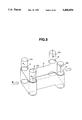
- FIG. 5 is a schematic cross-sectional view for explaining a solidity of the heat exchanger of FIG. 4;
- FIG. 6 is a perspective view which shows inlet and outlet ports of laminated tube elements of the heat exchanger of FIG. 1;
- FIG. 7 is a horizontal cross-sectional view of a second embodiment of the heat exchanger according to the present invention.
- FIG. 8 is a schematic perspective view of a third embodiment of the heat exchanger according to the present invention.
- FIG. 9 is a schematic perspective view of a fourth embodiment of the heat exchanger according to the present invention.
- FIG. 10 is a partial cross-sectional view of a fifth embodiment of the heat exchanger according to the present invention.
- FIG. 11 is a cross-sectional view of FIG. 10 taken in the direction of arrow substantially along the line XI--XI;
- FIG. 12 is a partial cross-sectional view of a sixth embodiment of the heat exchanger according to the present invention.
- FIG. 13 is a cross-sectional view of FIG. 12 taken in the direction of arrow substantially along the line XIII--XIII;
- FIG. 14 is a partial cross-sectional view of a seventh embodiment of the heat exchanger according to the present invention.
- FIG. 15 is a cross-sectional view of FIG. 14 taken in the direction of arrow substantially along the line XV--XV;
- FIG. 16 is a horizontal cross-sectional view of a conventional heat exchanger.
- FIGS. 1 to 6 there is shown a first embodiment of a heat exchanger H according to the present invention.
- the heat exchanger H comprises a plurality of tube elements 2 which define first-fluid passages 21, respectively, such that a low-temperature fluid A flows the first fluid passage 21.
- a plurality of inner fins 3 are disposed in the tube elements 2, respectively.
- Each of the tube elements 2 has two inlet ports 4 through which the low-temperature fluid A flows into the tube elements 2 and two outlet ports 5 through which the low-temperature fluid A flows out the tube elements 2. All of the inlet ports 4 and the outlet ports 5 are disposed so as to outwardly protrude from both lateral side portions 1a of each outer fin 1.
- the heat exchanger H has a housing 6 by which a second-fluid passage 22 for a high-temperature fluid B is defined.
- the tube elements 2 are alternately laminated with a plurality of outer fins 1 and disposed in the housing 6.
- An inlet duct 24 for the high-temperature fluid B is formed at one end of the housing 6, and an outlet duct 24 is formed at the other end of the housing 6.
- the heat exchanger H is arranged such that the low-temperature fluid A flows into the tube elements 2 from an upper portion of the inlet ports 4 and is distributed to the first passages 21 through the inlet ports 4, as shown by arrows in FIG. 3. Then, the low-temperature fluid A flows out through the outlet ports 5 to an upper side of the heat exchanger H.
- the heat exchanger H When the low-temperature fluid A and the high-temperature fluid B flow through the first-fluid passages 21 and the second-fluid passage 22, respectively, the heat transfer therebetween is implemented by the heat exchanger H.
- a pair of inlet ducts 4a are connected to the housing 6 to supply the low-temperature fluid A to the inlet ports 4.
- a pair of outlet ducts 5a are connected to the housing 6 to discharge the low-temperature fluid A from the outlet ports 5.
- each of the tube elements 2 is constituted by an upper plate 26 and a lower plate 27 which are assembled with each other while sandwiching an inner fin 3 therebetween.
- a peripheral portion 27b of the lower plate 27 is bent so as to surround a peripheral portion 26b of the upper plate 26, and the peripheral portions 26b and 27b are then connected in a self-locking joint.
- Four flanged through-holes 26a are formed at portions corresponding to the inlet and outlet ports of each upper plate 26.
- four flanged through-holes 27a are formed at portions corresponding to the inlet and outlet ports 4 and 5 of each lower plate 27.
- the flanged through-holes 26a of the upper plate 26 are engaged with the flanged through-holes 27a of the lower plate 27, respectively, and therefore the tube elements 2 are precisely fixed and positioned.
- Four U-shaped spacers 14 are inserted into each of the tube elements 2 so as to surround the inlet and outlet ports 4 and 5, respectively, as shown in FIGS. 1 and 4.
- Four ring-shaped spacers 15 are disposed so as to surround the engaged flanged through-holes 26a and 27b, respectively, as shown in FIGS. 2 and 4.
- Each of the spacers 15 is fixed to the upper and lower plates 26 and 27 by brazing. This brazing ensures the sealing performance at the inlet and outlet ports 4 and 5.
- the upper and lower plates 26 and 27, inner and outer fins 3 and 1, and spacers 14 and 15 are fixed to contacting surfaces therewith by brazing.
- the spacers 14 and 15 prevent the generation of dimensional variation between the upper and lower plates 26 and 27 and ensure resistance to loads and impacts. Accordingly, even if a weight 28 is put on the heat exchanger H as shown in FIG. 5, the heat exchanger H is durable without degrading the performance of the heat exchanger H.
- the spacers 14 and 15 improve the strength of the heat exchanger H, it is possible to reduce the requirement of the strength in the inner and outer fins 3 and 1. This enables the reduction of the thickness of the inner and outer fins 3 and 1, and therefore the pressure drop of the heat exchanger H is reduced.
- a pair of side plates 8 constituting side portions of the housing 6 are shaped along peripheral walls 2a and 2b of the tube elements 2 so as to form projections 8a, 8b and depressions 8c while keeping a predetermined space 11 between the tube elements 2 and the housing 6.
- the inner fins 3 and the outer fins 1 are corrugated and disposed such that the corrugated directions of fins 3 and 1 are the same.
- the inlet ports 4 are located in the vicinity of the outlet duct 25 of the second passage 22, and the outlet ports 5 are located in the vicinity of the inlet duct 24 of the second passage 22. That is, the flowing direction of the low-temperature fluid A directed by the inner fins 3 is opposite to the flowing direction of the high-temperature fluid B directed by the outer fins 1. Accordingly, the heat exchanger H functions as a counter-flow type heat exchanger.
- the low-temperature fluid A flows into the tube elements 2 through the inlet ports 4, then flows along the inner fins 3, and flows out from the outlet ports 5.
- the high-temperature fluid B flows into the housing 6 through the inlet duct 24, then flows along the outer fins 1, and flows out from the outlet duct 25.
- the thermal distribution in the tube elements 2 is equalized and therefore the heat transmission efficiency is improved as compared with a conventional cross-flow type heat exchanger. This enables the heat exchanger to become smaller.
- the drag of the passage formed by the housing 5 and the tube elements 2 is increased due to largely curved portions 13. Accordingly, the high-temperature fluid B mainly flows through the outer fins 1 while decreasing the amount of the flow passing through the clearance 11 between the housing 6 and the tube elements 2. Therefore, the heat transmission coefficient by this heat exchange H is improved.
- the high-temperature fluid B flows the curved portion 13 of the clearance 11, its pressure drop is 0.2 to 0.6 times of dynamic pressure.
- the pressure of the high-temperature fluid B is the atmospheric pressure
- the temperature is 500° C.
- the flow rate is 100 g/s
- the cross-sectional area of the clearance 11 is one-tenth of the total cross-sectional area of the passage for the fluid B, it is noted that the flow rate passing through the clearance 11 is greater than 10 g/s.
- the cross-sectional area of the clearance 11 is smaller than the 400 ⁇ 2 mm 2 . Accordingly the velocity of the high-temperature fluid B becomes larger than the value V expressed by the following equation.
- the cross-sectional area S 4 and the cross-sectional area S 5 are determined to satisfy the relationship represented by the equation (3), the variation of the momentum of the fluid B at the inlet and outlet ports 4 and 5 is suppressed to reduce the pressure drop.
- FIG. 7 there is shown a second embodiment of the heat exchanger H according to the present invention.
- corresponding parts to that of the first embodiment are designed by corresponding reference numerals of the first embodiment.
- the heat exchanger H is provided with the one inlet port 34 and the one outlet port 35 for the low-temperature fluid A.
- a cross-sectional area of the inlet port 34 is S 34
- the cross-sectional area of each inlet of each tube element 2 is t 34 and the number of the tube elements 2 is N
- the cross-sectional areas S 34 and t 34 and the number N are determined to satisfy the following equation (4):
- FIG. 8 there is shown a third embodiment of the heat exchanger H according to the present invention.
- the construction of the third embodiment is generally similar to that of the first embodiment except that the low-temperature fluid A is flowed into the tube elements 2 through four inlet ports 44 which are formed at upper two portions and lower two portions as shown in FIG. 8.
- FIG. 9 there is shown a fourth embodiment of the heat exchanger H according to the present invention.
- the construction of the fourth embodiment is generally similar to that of the first embodiment except that the low-temperature fluid A is flowed into the tube elements 2 through four inlet ports 44 which are formed at upper two portions and lower two portions, and flowed out through four outlet ports 45 which are formed at upper two portions and the lower two portion.
- FIGS. 10 and 11 there is shown a fifth embodiment of the heat exchanger H according to the present invention.
- the construction of the fifth embodiment is generally similar to that of the first embodiment.
- a plurality of columns 18 are disposed at a space 16 which communicates the inlet port 4 and the inner fin 3 in the tube element 2.
- the columns 18 are arranged along with a stream line of the low-temperature fluid A as shown in FIG. 10 so as to smoothly flow the low-temperature fluid A to the inner fin 3 without causing the stagnation in the space 16.
- the upper and lower plates 26 and 27 are provided with projections 26c and 27c formed by press working, respectively.
- the projections 26c and 27c are integrally connected by brazing and constitute the columns 18. Accordingly, the columns 18 function to improve the rigidity of the tube elements 3, more particularly the rigidity at parts of the upper and lower plates 26 and 27 corresponding to the space 6. Furthermore, the columns 18 function to suppress the deformation of the tube elements 2 during brazing.
- the pressure drop at the space 16 is reduced.
- the density of the low-temperature fluid A is ⁇
- an average velocity in the vicinity of the inlet port 4 in the inlet space 16 is 1/2 ⁇ v 2
- the pressure drop coefficient is ⁇
- the pressure drop at the inlet space 16 is represented by ⁇ v 2 /2. Since the columns 18 function as a guide member of the low-temperature fluid A, the pressure drop coefficient in this embodiment decreases by 1 at most.
- FIGS. 12 and 13 there is shown a sixth embodiment of the heat exchanger H according to the present invention.
- the construction of the sixth embodiment is generally similar to that of the first embodiment.
- a winglike guide member 19 is disposed at the space 16 which communicates the inlet port 4 and the inner fin 3 in the tube element 2.
- the guide member 18 is arranged such that a stream line of the low-temperature fluid A smoothly flows through the space 16 toward the inner fin 3 without causing the stagnation in the space 16.
- the guide member 19 also functions to improve the rigidity of the tube elements 2. Furthermore, the guide member 19 functions to suppress the deformation of the tube elements 2 during brazing.
- FIGS. 14 and 15 there is shown a seventh embodiment of the heat exchanger H according to the present invention.
- the construction of the seventh embodiment is generally similar to that of the sixth embodiment.
- a sub guide member 20 in addition to a winglike guide member 19 is disposed at the space 16 which communicates the inlet port 4 and the inner fin 3 in the tube element 2 as shown in FIG. 14.
- the sub guide member 20 is arranged with the winglike guide member 19 such that a stream line of the low-temperature fluid A further smoothly flows through the space 16 toward the inner fin 3 without causing the stagnation in the space 16.
- the winglike and sub guide members 19 and 20 also function to improve the rigidity of the tube elements 2.
- guide members are disposed in the space 18 between the inlet port and inner fin 3, it will be understood that such guide members may be installed in a space between the inner fin 3 and the outlet port 5 in the tube element 2.
Landscapes
- Engineering & Computer Science (AREA)
- Physics & Mathematics (AREA)
- Thermal Sciences (AREA)
- Mechanical Engineering (AREA)
- General Engineering & Computer Science (AREA)
- Heat-Exchange Devices With Radiators And Conduit Assemblies (AREA)
Applications Claiming Priority (2)
| Application Number | Priority Date | Filing Date | Title |
|---|---|---|---|
| JP5-044169 | 1993-03-04 | ||
| JP04416993A JP3359946B2 (ja) | 1993-03-04 | 1993-03-04 | 積層型熱交換器 |
Publications (1)
| Publication Number | Publication Date |
|---|---|
| US5400854A true US5400854A (en) | 1995-03-28 |
Family
ID=12684094
Family Applications (1)
| Application Number | Title | Priority Date | Filing Date |
|---|---|---|---|
| US08/205,869 Expired - Lifetime US5400854A (en) | 1993-03-04 | 1994-03-03 | Heat exchanger |
Country Status (3)
| Country | Link |
|---|---|
| US (1) | US5400854A (de) |
| JP (1) | JP3359946B2 (de) |
| DE (1) | DE4407080C2 (de) |
Cited By (25)
| Publication number | Priority date | Publication date | Assignee | Title |
|---|---|---|---|---|
| US20030015310A1 (en) * | 2001-07-12 | 2003-01-23 | Bernd Dienhart | Heat exchanger for a thermal coupling |
| US6516874B2 (en) * | 2001-06-29 | 2003-02-11 | Delaware Capital Formation, Inc. | All welded plate heat exchanger |
| US20030192685A1 (en) * | 2000-09-29 | 2003-10-16 | Calsonic Kansei Corporation | Heat exchanger |
| US6725912B1 (en) * | 1999-05-21 | 2004-04-27 | Aero Systems Engineering, Inc. | Wind tunnel and heat exchanger therefor |
| US20040182555A1 (en) * | 2001-03-27 | 2004-09-23 | Rekuperator Svenska Ab | Heat exchanger device and a method for manufacturing the same |
| US20050022982A1 (en) * | 2003-08-01 | 2005-02-03 | Roland Dilley | Heat exchanger with flow director |
| US20050081522A1 (en) * | 2002-03-17 | 2005-04-21 | Gottfried Raab | Internal combustion engine having two-stage exhaust-driven supercharger and charge air cooling between low pressure and high pressure compressors |
| US20050173103A1 (en) * | 2004-02-10 | 2005-08-11 | Peter Dawson | Flat plate heat exchanger coil and method of operating the same |
| US20060048759A1 (en) * | 2003-01-23 | 2006-03-09 | Behr Gmbh & Co. Kg | Device for exchanging heat |
| WO2007045719A1 (en) * | 2005-10-20 | 2007-04-26 | Vahterus Oy | Plate heat exchanger and method for constructing pressure-proof plate heat exchanger |
| US20090211740A1 (en) * | 2007-05-03 | 2009-08-27 | Brayton Energy, Llc | Heat Exchange Device and Method for Manufacture |
| US20090260787A1 (en) * | 2006-04-25 | 2009-10-22 | Modine Manufacruring Company | Heat exchanger for motor vehicles |
| US20120261099A1 (en) * | 2011-02-15 | 2012-10-18 | Sei Chugen | Heat Exchanger |
| EP2674714A1 (de) * | 2012-06-14 | 2013-12-18 | Alfa Laval Corporate AB | Plattenwärmetauscher mit Einspritzdüsen |
| US20140246185A1 (en) * | 2011-10-04 | 2014-09-04 | Valeo Systemes Thermiques | Heat Exchanger With Stacked Plates |
| US20140246183A1 (en) * | 2013-03-02 | 2014-09-04 | James Carl Loebig | Microchannel heat exchanger and methods of manufacture |
| US20150047818A1 (en) * | 2012-03-28 | 2015-02-19 | Modine Manufacturing Company | Heat exchanger |
| US20150342092A1 (en) * | 2014-05-23 | 2015-11-26 | Tesla Motors, Inc. | Heatsink with internal cavity for liquid cooling |
| US20160116218A1 (en) * | 2014-10-27 | 2016-04-28 | Ebullient, Llc | Heat exchanger with helical passageways |
| EP2336698B1 (de) * | 2009-12-16 | 2016-05-04 | MAHLE International GmbH | Plattenwärmeaustauscher mit Verstärkungseinsatzteil |
| US20170167805A1 (en) * | 2014-06-13 | 2017-06-15 | Honeywell International Inc. | Heat exchanger designs using variable geometries and configurations |
| US20180149433A1 (en) * | 2012-03-28 | 2018-05-31 | Modine Manufacturing Company | Heat Exchanger and Method of Cooling a Flow of Heated Air |
| US10619934B2 (en) | 2014-07-25 | 2020-04-14 | Airbus Helicopters | Plate heat exchanger comprising structural reinforcements for a turbine engine |
| US11268877B2 (en) | 2017-10-31 | 2022-03-08 | Chart Energy & Chemicals, Inc. | Plate fin fluid processing device, system and method |
| US11906218B2 (en) | 2014-10-27 | 2024-02-20 | Ebullient, Inc. | Redundant heat sink module |
Families Citing this family (11)
| Publication number | Priority date | Publication date | Assignee | Title |
|---|---|---|---|---|
| DE19836889A1 (de) * | 1998-08-14 | 2000-02-17 | Modine Mfg Co | Abgaswärmetauscher |
| DE19846518B4 (de) * | 1998-10-09 | 2007-09-20 | Modine Manufacturing Co., Racine | Wärmetauscher, insbesondere für Gase und Flüssigkeiten |
| DE10221016A1 (de) * | 2002-05-11 | 2003-11-27 | Ballard Power Systems | Reaktor |
| FR2855604B1 (fr) * | 2003-05-28 | 2008-09-26 | Valeo Thermique Moteur Sa | Echangeur de chaleur a plaques comportant un element d'obturation des fuites du gaz a fefroidir. |
| DE102005058769B4 (de) * | 2005-12-09 | 2016-11-03 | Modine Manufacturing Co. | Ladeluftkühler |
| DE102006005106A1 (de) * | 2006-02-04 | 2007-08-09 | Modine Manufacturing Co., Racine | Wärmetauscher mit einer Anschlussplatte, insbesondere Ladeluftkühler |
| DE102009003182A1 (de) * | 2009-05-18 | 2010-11-25 | Caradon Heating Europe B.V. | Verfahren zur Herstellung einer Heizplatte, Plattenheizkörper und Abstandhalter |
| DE102013201467B4 (de) * | 2013-01-30 | 2023-03-23 | Purem GmbH | Wärmetauscher einer Brennkraftmaschine und Brennkraftmaschine |
| JP6184904B2 (ja) * | 2014-06-06 | 2017-08-23 | 東京瓦斯株式会社 | 隔離板式熱交換器 |
| JP6764734B2 (ja) * | 2016-09-07 | 2020-10-07 | 株式会社Ihiプラント | 熱交換器 |
| JP6980607B2 (ja) * | 2018-06-28 | 2021-12-15 | 京セラ株式会社 | 熱交換器および熱交換システム |
Citations (7)
| Publication number | Priority date | Publication date | Assignee | Title |
|---|---|---|---|---|
| US1730139A (en) * | 1928-05-16 | 1929-10-01 | James M Harrison | Heat-exchanging apparatus |
| US2868514A (en) * | 1955-06-02 | 1959-01-13 | Hodson Peter | Mounting sinusoidal fin elements in heat exchange envelope |
| US3129756A (en) * | 1959-06-30 | 1964-04-21 | Ramen Torsten | Tube elements |
| FR2110168A7 (de) * | 1970-10-01 | 1972-06-02 | Linde Ag | |
| SU393568A1 (ru) * | 1971-06-21 | 1973-08-10 | Пластинчатый теплообменник | |
| JPS6349189U (de) * | 1986-09-16 | 1988-04-02 | ||
| US5301747A (en) * | 1991-12-20 | 1994-04-12 | Balcke-Durr Aktiengesellschaft | Heat exchanger comprised of individual plates |
Family Cites Families (2)
| Publication number | Priority date | Publication date | Assignee | Title |
|---|---|---|---|---|
| US4002201A (en) * | 1974-05-24 | 1977-01-11 | Borg-Warner Corporation | Multiple fluid stacked plate heat exchanger |
| DE2706253A1 (de) * | 1977-02-15 | 1978-08-17 | Rosenthal Technik Ag | Keramischer, rekuperativer gegenstromwaermetauscher |
-
1993
- 1993-03-04 JP JP04416993A patent/JP3359946B2/ja not_active Expired - Lifetime
-
1994
- 1994-03-03 US US08/205,869 patent/US5400854A/en not_active Expired - Lifetime
- 1994-03-03 DE DE4407080A patent/DE4407080C2/de not_active Expired - Fee Related
Patent Citations (7)
| Publication number | Priority date | Publication date | Assignee | Title |
|---|---|---|---|---|
| US1730139A (en) * | 1928-05-16 | 1929-10-01 | James M Harrison | Heat-exchanging apparatus |
| US2868514A (en) * | 1955-06-02 | 1959-01-13 | Hodson Peter | Mounting sinusoidal fin elements in heat exchange envelope |
| US3129756A (en) * | 1959-06-30 | 1964-04-21 | Ramen Torsten | Tube elements |
| FR2110168A7 (de) * | 1970-10-01 | 1972-06-02 | Linde Ag | |
| SU393568A1 (ru) * | 1971-06-21 | 1973-08-10 | Пластинчатый теплообменник | |
| JPS6349189U (de) * | 1986-09-16 | 1988-04-02 | ||
| US5301747A (en) * | 1991-12-20 | 1994-04-12 | Balcke-Durr Aktiengesellschaft | Heat exchanger comprised of individual plates |
Cited By (44)
| Publication number | Priority date | Publication date | Assignee | Title |
|---|---|---|---|---|
| US6725912B1 (en) * | 1999-05-21 | 2004-04-27 | Aero Systems Engineering, Inc. | Wind tunnel and heat exchanger therefor |
| US20030192685A1 (en) * | 2000-09-29 | 2003-10-16 | Calsonic Kansei Corporation | Heat exchanger |
| US20040182555A1 (en) * | 2001-03-27 | 2004-09-23 | Rekuperator Svenska Ab | Heat exchanger device and a method for manufacturing the same |
| US7228892B2 (en) * | 2001-03-27 | 2007-06-12 | Rekuperator Svenska Ab | Heat exchanger device and a method for manufacturing the same |
| US6516874B2 (en) * | 2001-06-29 | 2003-02-11 | Delaware Capital Formation, Inc. | All welded plate heat exchanger |
| US20030015310A1 (en) * | 2001-07-12 | 2003-01-23 | Bernd Dienhart | Heat exchanger for a thermal coupling |
| US7191769B2 (en) * | 2002-03-17 | 2007-03-20 | Man Steyr Ag | Internal combustion engine having two-stage exhaust-driven supercharger and charge air cooling between low pressure and high pressure compressors |
| US20050081522A1 (en) * | 2002-03-17 | 2005-04-21 | Gottfried Raab | Internal combustion engine having two-stage exhaust-driven supercharger and charge air cooling between low pressure and high pressure compressors |
| US7571718B2 (en) * | 2003-01-23 | 2009-08-11 | Behr Gmbh & Co. Kg | Device for exchanging heat |
| US20060048759A1 (en) * | 2003-01-23 | 2006-03-09 | Behr Gmbh & Co. Kg | Device for exchanging heat |
| US6997250B2 (en) * | 2003-08-01 | 2006-02-14 | Honeywell International, Inc. | Heat exchanger with flow director |
| US20050022982A1 (en) * | 2003-08-01 | 2005-02-03 | Roland Dilley | Heat exchanger with flow director |
| US20060278368A1 (en) * | 2004-02-10 | 2006-12-14 | Peter Dawson | Apparatus for cleaning heat exchanger plates and a bulk material heat exchanger using the same |
| US20060278367A1 (en) * | 2004-02-10 | 2006-12-14 | Peter Dawson | Flat heat exchanger plate and bulk material heat exchanger using the same |
| US7093649B2 (en) * | 2004-02-10 | 2006-08-22 | Peter Dawson | Flat heat exchanger plate and bulk material heat exchanger using the same |
| US8997841B2 (en) | 2004-02-10 | 2015-04-07 | Peter Dawson | Flat heat exchanger plate and bulk material heat exchanger using the same |
| US20050173103A1 (en) * | 2004-02-10 | 2005-08-11 | Peter Dawson | Flat plate heat exchanger coil and method of operating the same |
| US7264039B2 (en) | 2004-02-10 | 2007-09-04 | Peter Dawson | Apparatus for cleaning heat exchanger plates and a bulk material heat exchanger using the same |
| WO2007045719A1 (en) * | 2005-10-20 | 2007-04-26 | Vahterus Oy | Plate heat exchanger and method for constructing pressure-proof plate heat exchanger |
| US20090260787A1 (en) * | 2006-04-25 | 2009-10-22 | Modine Manufacruring Company | Heat exchanger for motor vehicles |
| US8371365B2 (en) * | 2007-05-03 | 2013-02-12 | Brayton Energy, Llc | Heat exchange device and method for manufacture |
| US20090211740A1 (en) * | 2007-05-03 | 2009-08-27 | Brayton Energy, Llc | Heat Exchange Device and Method for Manufacture |
| EP2336698B1 (de) * | 2009-12-16 | 2016-05-04 | MAHLE International GmbH | Plattenwärmeaustauscher mit Verstärkungseinsatzteil |
| US20120261099A1 (en) * | 2011-02-15 | 2012-10-18 | Sei Chugen | Heat Exchanger |
| US9182176B2 (en) * | 2011-02-15 | 2015-11-10 | Chugen Sei | Heat exchanger |
| US20140246185A1 (en) * | 2011-10-04 | 2014-09-04 | Valeo Systemes Thermiques | Heat Exchanger With Stacked Plates |
| US10690421B2 (en) * | 2012-03-28 | 2020-06-23 | Modine Manufacturing Company | Heat exchanger and method of cooling a flow of heated air |
| US20150047818A1 (en) * | 2012-03-28 | 2015-02-19 | Modine Manufacturing Company | Heat exchanger |
| US20180149433A1 (en) * | 2012-03-28 | 2018-05-31 | Modine Manufacturing Company | Heat Exchanger and Method of Cooling a Flow of Heated Air |
| US9909812B2 (en) * | 2012-03-28 | 2018-03-06 | Modine Manufacturing Company | Heat exchanger |
| EP2674714A1 (de) * | 2012-06-14 | 2013-12-18 | Alfa Laval Corporate AB | Plattenwärmetauscher mit Einspritzdüsen |
| US10107572B2 (en) | 2012-06-14 | 2018-10-23 | Alfa Lavalcorporate Ab | Plate heat exchanger |
| US20140246183A1 (en) * | 2013-03-02 | 2014-09-04 | James Carl Loebig | Microchannel heat exchanger and methods of manufacture |
| US10178805B2 (en) * | 2014-05-23 | 2019-01-08 | Tesla, Inc. | Heatsink with internal cavity for liquid cooling |
| KR20160142343A (ko) * | 2014-05-23 | 2016-12-12 | 테슬라 모터스, 인크. | 액체 냉각을 위한 내부 캐비티를 갖는 히트싱크 |
| US20150342092A1 (en) * | 2014-05-23 | 2015-11-26 | Tesla Motors, Inc. | Heatsink with internal cavity for liquid cooling |
| US20170167805A1 (en) * | 2014-06-13 | 2017-06-15 | Honeywell International Inc. | Heat exchanger designs using variable geometries and configurations |
| US10222142B2 (en) * | 2014-06-13 | 2019-03-05 | Honeywell International Inc. | Heat exchanger designs using variable geometries and configurations |
| US10619934B2 (en) | 2014-07-25 | 2020-04-14 | Airbus Helicopters | Plate heat exchanger comprising structural reinforcements for a turbine engine |
| US20160116218A1 (en) * | 2014-10-27 | 2016-04-28 | Ebullient, Llc | Heat exchanger with helical passageways |
| US20160116222A1 (en) * | 2014-10-27 | 2016-04-28 | Ebullient, Llc | Heat exchanger with interconnected fluid transfer members |
| US9891002B2 (en) * | 2014-10-27 | 2018-02-13 | Ebullient, Llc | Heat exchanger with interconnected fluid transfer members |
| US11906218B2 (en) | 2014-10-27 | 2024-02-20 | Ebullient, Inc. | Redundant heat sink module |
| US11268877B2 (en) | 2017-10-31 | 2022-03-08 | Chart Energy & Chemicals, Inc. | Plate fin fluid processing device, system and method |
Also Published As
| Publication number | Publication date |
|---|---|
| DE4407080A1 (de) | 1994-09-08 |
| DE4407080C2 (de) | 2001-02-01 |
| JPH06257982A (ja) | 1994-09-16 |
| JP3359946B2 (ja) | 2002-12-24 |
Similar Documents
| Publication | Publication Date | Title |
|---|---|---|
| US5400854A (en) | Heat exchanger | |
| JP4756585B2 (ja) | 熱交換器用伝熱管 | |
| US5107922A (en) | Optimized offset strip fin for use in contact heat exchangers | |
| US6820682B2 (en) | Heat exchanger | |
| US8069905B2 (en) | EGR gas cooling device | |
| US7334631B2 (en) | Heat exchanger | |
| US7077190B2 (en) | Exhaust gas heat exchanger | |
| US6415855B2 (en) | Corrugated fin with partial offset for a plate-type heat exchanger and corresponding plate-type heat exchanger | |
| US5329988A (en) | Heat exchanger | |
| US8267163B2 (en) | Radiator tube dimple pattern | |
| KR100643531B1 (ko) | 딤플 우회 채널을 갖는 열교환기 | |
| US4958681A (en) | Heat exchanger with bypass channel louvered fins | |
| US4789027A (en) | Ribbed heat exchanger | |
| KR20140118878A (ko) | 공기 대 공기 열 교환기 | |
| US3515207A (en) | Fin configuration for fin and tube heat exchanger | |
| US4465128A (en) | Plate floor heat exchanger | |
| US20090087604A1 (en) | Extruded tube for use in heat exchanger | |
| US5373895A (en) | Heat exchanger | |
| US8689858B2 (en) | Cooler block, especially for a change air cooler/coolant cooler | |
| JPH0547960Y2 (de) | ||
| JPS5916693Y2 (ja) | 熱交換器 | |
| SU1733895A1 (ru) | Пластинчатый теплообменник | |
| JPH07280466A (ja) | 熱交換器 | |
| JPS593269Y2 (ja) | 多板式熱交換器 | |
| RU2047076C1 (ru) | Теплообменник |
Legal Events
| Date | Code | Title | Description |
|---|---|---|---|
| AS | Assignment |
Owner name: TOKYO RADIATOR MFG. CO., LTD., JAPAN Free format text: ASSIGNMENT OF ASSIGNORS INTEREST;ASSIGNOR:IIO, MASATOSHI;REEL/FRAME:006946/0512 Effective date: 19940211 Owner name: NISSAN MOTOR CO., LTD., JAPAN Free format text: ASSIGNMENT OF ASSIGNORS INTEREST;ASSIGNOR:KIMURA, MITUO;REEL/FRAME:006946/0509 Effective date: 19940217 Owner name: NISSAN MOTOR CO., LTD., JAPAN Free format text: ASSIGNMENT OF ASSIGNORS INTEREST;ASSIGNOR:IIO, MASATOSHI;REEL/FRAME:006946/0512 Effective date: 19940211 |
|
| FEPP | Fee payment procedure |
Free format text: PAYOR NUMBER ASSIGNED (ORIGINAL EVENT CODE: ASPN); ENTITY STATUS OF PATENT OWNER: LARGE ENTITY |
|
| STCF | Information on status: patent grant |
Free format text: PATENTED CASE |
|
| FPAY | Fee payment |
Year of fee payment: 4 |
|
| AS | Assignment |
Owner name: IHI AEROSPACE CO., LTD., JAPAN Free format text: ASSIGNMENT OF ASSIGNORS INTEREST;ASSIGNOR:NISSAN MOTOR CO., LTD.;REEL/FRAME:011499/0112 Effective date: 20010123 |
|
| FPAY | Fee payment |
Year of fee payment: 8 |
|
| FPAY | Fee payment |
Year of fee payment: 12 |