US5375697A - Conveyor chain - Google Patents
Conveyor chain Download PDFInfo
- Publication number
- US5375697A US5375697A US08/056,414 US5641493A US5375697A US 5375697 A US5375697 A US 5375697A US 5641493 A US5641493 A US 5641493A US 5375697 A US5375697 A US 5375697A
- Authority
- US
- United States
- Prior art keywords
- arms
- links
- pin
- situated
- link
- Prior art date
- Legal status (The legal status is an assumption and is not a legal conclusion. Google has not performed a legal analysis and makes no representation as to the accuracy of the status listed.)
- Expired - Lifetime
Links
Images

Classifications
-
- B—PERFORMING OPERATIONS; TRANSPORTING
- B65—CONVEYING; PACKING; STORING; HANDLING THIN OR FILAMENTARY MATERIAL
- B65G—TRANSPORT OR STORAGE DEVICES, e.g. CONVEYORS FOR LOADING OR TIPPING, SHOP CONVEYOR SYSTEMS OR PNEUMATIC TUBE CONVEYORS
- B65G17/00—Conveyors having an endless traction element, e.g. a chain, transmitting movement to a continuous or substantially-continuous load-carrying surface or to a series of individual load-carriers; Endless-chain conveyors in which the chains form the load-carrying surface
- B65G17/06—Conveyors having an endless traction element, e.g. a chain, transmitting movement to a continuous or substantially-continuous load-carrying surface or to a series of individual load-carriers; Endless-chain conveyors in which the chains form the load-carrying surface having a load-carrying surface formed by a series of interconnected, e.g. longitudinal, links, plates, or platforms
- B65G17/08—Conveyors having an endless traction element, e.g. a chain, transmitting movement to a continuous or substantially-continuous load-carrying surface or to a series of individual load-carriers; Endless-chain conveyors in which the chains form the load-carrying surface having a load-carrying surface formed by a series of interconnected, e.g. longitudinal, links, plates, or platforms the surface being formed by the traction element
- B65G17/086—Conveyors having an endless traction element, e.g. a chain, transmitting movement to a continuous or substantially-continuous load-carrying surface or to a series of individual load-carriers; Endless-chain conveyors in which the chains form the load-carrying surface having a load-carrying surface formed by a series of interconnected, e.g. longitudinal, links, plates, or platforms the surface being formed by the traction element specially adapted to follow a curved path
-
- B—PERFORMING OPERATIONS; TRANSPORTING
- B65—CONVEYING; PACKING; STORING; HANDLING THIN OR FILAMENTARY MATERIAL
- B65G—TRANSPORT OR STORAGE DEVICES, e.g. CONVEYORS FOR LOADING OR TIPPING, SHOP CONVEYOR SYSTEMS OR PNEUMATIC TUBE CONVEYORS
- B65G2201/00—Indexing codes relating to handling devices, e.g. conveyors, characterised by the type of product or load being conveyed or handled
- B65G2201/02—Articles
Definitions
- This invention concerns a perfected conveyor chain.
- the invention relates to those chains whose links can oscillate both at a fight angle to and parallel to their lying position, in such a way as to be able to close in a ring, creating at the same time curves in the plane of the links.
- conveyor chains to which this present invention refers particularly, whose links are composed of a shaped element obtained by the molding of a synthetic material such as acetal resin.
- the links of said known chains include a body which is in the shape of a fork and a monolithic plate which is used to close the aperture defined by said fork, from the part of the latter that defines the active zone or conveying zone of the link.
- the crosspiece of said fork is shaped like a bush from whose end two divergent shaped arms derive.
- the bush of the link of chain that follows is inserted between said two arms, and transversally to said arms there is a cylindrical pin which, crossing the bush, connects the two links.
- Said cylindrical pin is inserted into a seat of articulation and oscillation that is formed in the bush of the link of chain that follows, and which is shaped, in right-angle section, like an eyelet whose lying plane is at a right angle to that of the link.
- the cylindrical pin can rotate in its seat, and also oscillate in the plane of the respective link.
- said seat shaped like an eyelet requires that the size of the bush, in the sense of the axis of the link, be considerable, to allow a sufficient possibility of oscillation, between two adjacent links, in their plane.
- the main objective of this present invention is to make available a conveyor chain that is able to comply with the need mentioned first, and to overcome the problem mentioned afterward.
- Said chain presents a seat for insertion of the pin in the bush whose straight section is circular in the lower part (with reference to the forward direction of the chain), while said seat is created in the front part by two flat walls that converge at the center where they form a cusp, whose vertex determines a narrowing of said seat.
- the pin inserted in said seat consists of a cylindrical rod with a longitudinal flattening facing the flat walls of the seat.
- the distance that exists between the vertex of said cusp and the opposite wall of said seat is slightly greater than the diameter of said pin, in such a way as to allow the latter to rotate in its seat and to oscillate in correspondence with the vertex of said cusp.
- the outer sides of the arms of the fork-shaped body include protruding retaining elements whose function, in combination with special guides, is to maintain the engagement between links and pinion when the chain follows sharp curves (fight angle to the lying plane of the links) and is subject to heavy operating conditions.
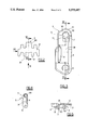
- FIG. 1 is a side view of a curved tract of a conveyor chain as per this present invention
- FIG. 2 shows a link of the chain according to a plan view from the part of the active zone or conveying of the chain
- FIG. 3 is the view obtained according to the direction III as per FIG. 2, in enlarged scale;
- FIG. 4 is the IV--IV section marked in FIG. 3, on a smaller scale, and in the right part of this drawing there is a longitudinal view and a transverse view in section of the pin for articulation between the links;
- FIG. 5 is the view obtained according to the direction V marked in FIG. 2, and
- FIG. 6 is the VI--VI section marked in FIG. 2.
- FIG. 1 there is a drawing pinion 1 with horizontal axis for drawing a conveyor chain as per this present invention.
- the pinion 1 is commanded to rotate in the direction shown by A, and this same pinion 1 presents, in the specific case, nine teeth.
- two lateral guides 2 opposite one another are associated to the tract of advancement of the chain, of which only one is visible in FIG. 1, and said guides also follow the curving of the pinion 1 substantially for a fourth of the round angle. We will return to said guides 2 further on.
- each individual link includes a basic body 3 in the shape of a fork, and the aperture of said fork is partially closed by a monolithic shaped plate 4.
- Said plate 4 defines the active surface of the conveyor chain, and has an elongated form situated transversally to the axis of symmetry of said fork.
- front and rear edges of said plate 4 have respective toothing that is reciprocally staggered, which is used to stabilize the continuity of the active surface of the chain, in collaboration with the identical teeth of the adjacent links, even when the chain follows curves (not illustrated) contained in the lying plane of the links.
- the crosspiece of said fork consists of a bush 30 that is destined to be inserted between the arms 31 of the fork of the subsequent link.
- Said bush 30 is joined to the outer face of plate 4 (see FIG. 6), and said bush 30 forms the tooth of the link that is destined to be inserted in the openings of pinion 1 (see FIG. 1).
- transverse pin 5 that is illustrated in the right part of FIG. 4.
- Said pin 5 consists of a cylindrical rod that has a longitudinal flattening 50 from which rise two small transverse end ribbings 51 that are opposite one another.
- said flattening 50 subtends an angle of approximately 115°, and the sides of said ribbings 51 are appropriately bevelled.
- the terminal parts of pin 5 are blocked in respective coaxial openings 6 that are made on the free ends of the arms 31 of one link of said pair, while the central portion of said pin 5 is inserted into a seat 7 of articulation and oscillation that is made in the bush 30 of the other link of said pair.
- transverse section of said openings 6 is practically equal to the right angle section of pin 5, excluding the ribbings 51 (FIGS. 3, 4).
- the length of pin 5 is slightly less than the maximum distance between the outer sides of the arms 31, and the distance between the outer sides of the two ribbings 51 is substantially equal to the distance between the inner sides of said arms.
- pin 5 is blocked both torsionally and axially with respect to the arms 31, with the flattening 50 orientated toward the free ends of the latter.
- said seat presents a shaped form, like a slot with a narrowing in the center.
- Said slot is contained in a plane that is parallel to the lying plane of the link, and that also contains the common axis of said pair of openings 6.
- the width of the slit is practically equal to the diameter of pin 5.
- terminal walls of said seat 7 that are turned respectively toward the cylindrical and flat parts 50 of pin 5 are shaped, respectively, like a semi-cylindrical surface 70 (FIGS. 3, 6) and like a symmetrical cusp 71 (FIG. 4).
- said cusp 71 is defined by two inclined planes arranged according to a very open "V", whose opening is turned toward the arms 31 (FIG. 4).
- the distance that exists between the median generating line of said semi-cylindrical surface 70 and the vertex of said cusp 71 is slightly greater than the diameter of pin 5. The reason for this is to prevent interference when the chain goes into a curve as is easy to understand from FIG. 1.
- the distance just defined also has the function, in combination with the bevellings 72 and the cusp 71, of allowing the links to follow curves contained in their lying planes.
- Said fins 8 are situated on the part of the arms 31 that is opposite to that occupied by plate 4, and said fins 8 are located between the seat 7 and the openings 6 (FIGS. 1, 3).
- said fins 8 are shaped like a wing profile.
- each fin 8 is a first fin 8
Applications Claiming Priority (2)
| Application Number | Priority Date | Filing Date | Title |
|---|---|---|---|
| IT92RE000040U IT228636Y1 (it) | 1992-05-07 | 1992-05-07 | Catena di trasporto |
| ITRE92U000040 | 1992-05-07 |
Publications (1)
| Publication Number | Publication Date |
|---|---|
| US5375697A true US5375697A (en) | 1994-12-27 |
Family
ID=11398204
Family Applications (1)
| Application Number | Title | Priority Date | Filing Date |
|---|---|---|---|
| US08/056,414 Expired - Lifetime US5375697A (en) | 1992-05-07 | 1993-05-03 | Conveyor chain |
Country Status (8)
| Country | Link |
|---|---|
| US (1) | US5375697A (it) |
| EP (1) | EP0569071B2 (it) |
| JP (1) | JP2605451Y2 (it) |
| AT (1) | ATE138877T1 (it) |
| DE (1) | DE69302961T3 (it) |
| DK (1) | DK0569071T4 (it) |
| ES (1) | ES2088219T5 (it) |
| IT (1) | IT228636Y1 (it) |
Cited By (10)
| Publication number | Priority date | Publication date | Assignee | Title |
|---|---|---|---|---|
| USD420483S (en) * | 1997-10-06 | 2000-02-08 | Flexlink Systems Ab | Chain-link to a conveyor |
| US6079553A (en) * | 1997-01-14 | 2000-06-27 | Tsubakimoto Chain Co. | Carrier chain |
| US6202834B1 (en) * | 1998-03-03 | 2001-03-20 | Span Tech Llc | Modular link conveyor with I-beam guide rail |
| US6543609B2 (en) | 2001-02-15 | 2003-04-08 | Span Tech Llc | Split sprocket housing for a conveyor system and related method |
| US6736259B1 (en) * | 1999-11-16 | 2004-05-18 | Yamakyu Chain Co., Ltd. | Chain for three-dimensional transfer line |
| US20050183936A1 (en) * | 2004-02-20 | 2005-08-25 | Ashworth Bros., Inc. . | Conveyor belt and method of assembly |
| US20080067040A1 (en) * | 2006-08-30 | 2008-03-20 | Laitram, L.L.C. | Abrasion-resistant hinge rods in modular plastic conveyor belts |
| US9085414B2 (en) | 2012-11-29 | 2015-07-21 | Solus Industrial Innovations, Llc | Side-flexing conveyors |
| US9102476B2 (en) | 2012-10-25 | 2015-08-11 | Solus Industrial Innovations, Llc | Conveyor system wear indication devices and methods |
| CN106865119A (zh) * | 2017-04-13 | 2017-06-20 | 湖南尔瞻智能科技有限公司 | 防脱落链条 |
Families Citing this family (11)
| Publication number | Priority date | Publication date | Assignee | Title |
|---|---|---|---|---|
| ITBO20030453A1 (it) * | 2003-07-29 | 2005-01-30 | Pulsar Srl | Dispositivo di convogliamento senza accumulo di residui. |
| US9850072B2 (en) | 2007-02-08 | 2017-12-26 | Habasit Ag | Cleaning-in-place system for flat belts |
| JP5023346B2 (ja) * | 2007-05-24 | 2012-09-12 | 株式会社瑞光 | ウェブの折り装置、ウェブの折り方法および着用物品の製造方法 |
| US8997975B2 (en) | 2010-08-13 | 2015-04-07 | Habasit Ag | Sprockets for a flexible conveyor belt and conveyor belt system |
| JP5881702B2 (ja) * | 2010-08-13 | 2016-03-09 | ハバシット アクチエンゲゼルシャフト | 平ベルト用の定置洗浄システム |
| DE102011112398A1 (de) | 2011-09-03 | 2013-03-07 | Robert Bosch Gmbh | Förderkettenglied mit L-förmiger Bolzenausnehmung |
| DE102011112396A1 (de) | 2011-09-03 | 2013-03-07 | Robert Bosch Gmbh | Kettenglied mit durch Gleitabschnitt getrennten Gelenk- und Gabelabschnitt |
| DE102013015935A1 (de) | 2013-09-25 | 2015-04-16 | Iwis Antriebssysteme Gmbh & Co. Kg | Multiflexkette |
| KR200483153Y1 (ko) * | 2016-02-22 | 2017-04-10 | 김광수 | 단차가 형성되는 컨베이어 체인 링크 |
| DE102018130807A1 (de) * | 2018-12-04 | 2020-06-04 | Homag Gmbh | Transportmittel, Transportsystem und Bearbeitungsmaschine |
| KR102646159B1 (ko) * | 2023-04-05 | 2024-03-08 | 최종옥 | 나선형 컨베이어 체인링크 |
Citations (8)
| Publication number | Priority date | Publication date | Assignee | Title |
|---|---|---|---|---|
| US3520398A (en) * | 1967-11-30 | 1970-07-14 | Rex Chainbelt Inc | Laterally flexible conveyor |
| FR2564810A1 (fr) * | 1984-05-24 | 1985-11-29 | Faber Sa | Axe a bossage pour chaine de convoyage |
| US4597492A (en) * | 1981-09-30 | 1986-07-01 | Aktiebolaget Skf | Conveyor chain |
| US4682687A (en) * | 1982-05-14 | 1987-07-28 | Rexnord Inc. | Pintle chain including self-retaining pin |
| US4754872A (en) * | 1986-01-30 | 1988-07-05 | Damkjaer Poul E | Conveyor chain link |
| US4893709A (en) * | 1988-08-18 | 1990-01-16 | Rexnord Corporation | Back-flexing article carrying chain |
| US5096050A (en) * | 1981-06-02 | 1992-03-17 | Rexnord Corporation | Low backline pressure chain |
| US5156264A (en) * | 1988-11-14 | 1992-10-20 | The Laitram Corporation | Non-destructive pivot rod retention apparatus for modular plastic conveyor belts |
Family Cites Families (4)
| Publication number | Priority date | Publication date | Assignee | Title |
|---|---|---|---|---|
| US3529715A (en) * | 1968-05-02 | 1970-09-22 | Rex Chainbelt Inc | Stamped side-flex conveyor chain |
| US3804232A (en) † | 1972-12-04 | 1974-04-16 | Rexnord Inc | Structurally balanced plastic conveyor chain |
| DE3818231A1 (de) * | 1988-05-28 | 1989-12-07 | Rexnord Kette Gmbh & Co Kg | Kurvengaengiger plattenbandfoerderer |
| GB2225761A (en) * | 1988-12-06 | 1990-06-13 | Baeltix Maskinfabrikken As | Conveyor chain link |
-
1992
- 1992-05-07 IT IT92RE000040U patent/IT228636Y1/it active IP Right Grant
-
1993
- 1993-04-09 ES ES93201051T patent/ES2088219T5/es not_active Expired - Lifetime
- 1993-04-09 AT AT93201051T patent/ATE138877T1/de active
- 1993-04-09 EP EP93201051A patent/EP0569071B2/en not_active Expired - Lifetime
- 1993-04-09 DK DK93201051T patent/DK0569071T4/da active
- 1993-04-09 DE DE69302961T patent/DE69302961T3/de not_active Expired - Fee Related
- 1993-04-20 JP JP1993020331U patent/JP2605451Y2/ja not_active Expired - Fee Related
- 1993-05-03 US US08/056,414 patent/US5375697A/en not_active Expired - Lifetime
Patent Citations (8)
| Publication number | Priority date | Publication date | Assignee | Title |
|---|---|---|---|---|
| US3520398A (en) * | 1967-11-30 | 1970-07-14 | Rex Chainbelt Inc | Laterally flexible conveyor |
| US5096050A (en) * | 1981-06-02 | 1992-03-17 | Rexnord Corporation | Low backline pressure chain |
| US4597492A (en) * | 1981-09-30 | 1986-07-01 | Aktiebolaget Skf | Conveyor chain |
| US4682687A (en) * | 1982-05-14 | 1987-07-28 | Rexnord Inc. | Pintle chain including self-retaining pin |
| FR2564810A1 (fr) * | 1984-05-24 | 1985-11-29 | Faber Sa | Axe a bossage pour chaine de convoyage |
| US4754872A (en) * | 1986-01-30 | 1988-07-05 | Damkjaer Poul E | Conveyor chain link |
| US4893709A (en) * | 1988-08-18 | 1990-01-16 | Rexnord Corporation | Back-flexing article carrying chain |
| US5156264A (en) * | 1988-11-14 | 1992-10-20 | The Laitram Corporation | Non-destructive pivot rod retention apparatus for modular plastic conveyor belts |
Cited By (15)
| Publication number | Priority date | Publication date | Assignee | Title |
|---|---|---|---|---|
| US6079553A (en) * | 1997-01-14 | 2000-06-27 | Tsubakimoto Chain Co. | Carrier chain |
| USD420483S (en) * | 1997-10-06 | 2000-02-08 | Flexlink Systems Ab | Chain-link to a conveyor |
| US6202834B1 (en) * | 1998-03-03 | 2001-03-20 | Span Tech Llc | Modular link conveyor with I-beam guide rail |
| US6736259B1 (en) * | 1999-11-16 | 2004-05-18 | Yamakyu Chain Co., Ltd. | Chain for three-dimensional transfer line |
| US6543609B2 (en) | 2001-02-15 | 2003-04-08 | Span Tech Llc | Split sprocket housing for a conveyor system and related method |
| US7073662B2 (en) | 2004-02-20 | 2006-07-11 | Ashworth Bros., Inc. | Conveyor belt and method of assembly |
| US20050183936A1 (en) * | 2004-02-20 | 2005-08-25 | Ashworth Bros., Inc. . | Conveyor belt and method of assembly |
| US20080067040A1 (en) * | 2006-08-30 | 2008-03-20 | Laitram, L.L.C. | Abrasion-resistant hinge rods in modular plastic conveyor belts |
| US7438179B2 (en) | 2006-08-30 | 2008-10-21 | Laitram, L.L.C. | Abrasion-resistant hinge rods in modular plastic conveyor belts |
| US9102476B2 (en) | 2012-10-25 | 2015-08-11 | Solus Industrial Innovations, Llc | Conveyor system wear indication devices and methods |
| US9409721B2 (en) | 2012-10-25 | 2016-08-09 | Solus Industrial Innovations, Llc | Conveyor system wear indication devices and methods |
| US9085414B2 (en) | 2012-11-29 | 2015-07-21 | Solus Industrial Innovations, Llc | Side-flexing conveyors |
| US9751694B2 (en) | 2012-11-29 | 2017-09-05 | Solus Industrial Innovations, Llc | Side-flexing conveyors |
| CN106865119A (zh) * | 2017-04-13 | 2017-06-20 | 湖南尔瞻智能科技有限公司 | 防脱落链条 |
| CN106865119B (zh) * | 2017-04-13 | 2019-01-29 | 湖南尔瞻智能科技有限公司 | 防脱落链条 |
Also Published As
| Publication number | Publication date |
|---|---|
| DE69302961D1 (de) | 1996-07-11 |
| EP0569071B1 (en) | 1996-06-05 |
| DE69302961T2 (de) | 1996-11-28 |
| DK0569071T3 (da) | 1996-10-14 |
| DE69302961T3 (de) | 2001-04-19 |
| EP0569071A1 (en) | 1993-11-10 |
| ATE138877T1 (de) | 1996-06-15 |
| ITRE920040V0 (it) | 1992-05-07 |
| JPH0595914U (ja) | 1993-12-27 |
| ES2088219T3 (es) | 1996-08-01 |
| ITRE920040U1 (it) | 1993-11-07 |
| IT228636Y1 (it) | 1998-05-07 |
| ES2088219T5 (es) | 2000-12-01 |
| JP2605451Y2 (ja) | 2000-07-17 |
| DK0569071T4 (da) | 2000-11-06 |
| EP0569071B2 (en) | 2000-07-26 |
Similar Documents
| Publication | Publication Date | Title |
|---|---|---|
| US5375697A (en) | Conveyor chain | |
| AU2006312216B2 (en) | Conveyor belt | |
| US3231069A (en) | Chain link | |
| JP5368684B2 (ja) | 革新的駆動連結具を備えたチェーンコンベアベルト | |
| CA2517677C (en) | Modular conveying assembly having roller cradles | |
| US3066549A (en) | Conveyor chain | |
| US4904231A (en) | Rocker joint for chain | |
| KR100570934B1 (ko) | 측방굴곡컨베이어 | |
| US3160024A (en) | Link member | |
| EP1163839B1 (de) | Abstreifer und Gutförderer | |
| US2672059A (en) | Sprocket chain | |
| DE3110833C2 (de) | Fördereinrichtung | |
| US4974722A (en) | Multi-strand chain conveyor | |
| EP0569072A1 (en) | Chain for conveyor systems | |
| DE2433345A1 (de) | Verkuerzungsklaue fuer gliederkettenstraenge | |
| US2495951A (en) | Sling and end fitting | |
| US2775338A (en) | Channel bars connecting link | |
| US3415136A (en) | Link chain | |
| US4487013A (en) | T-rod chain | |
| US3826150A (en) | Link configuration for distribution of transverse loads on drive and drag chain | |
| US160107A (en) | Improvement in chain-links and chains | |
| US1999484A (en) | Conveyer | |
| USD12794S (en) | Design for an ornamental chain | |
| US1690745A (en) | Choker hook | |
| US2579394A (en) | Linked connector and method of making same |
Legal Events
| Date | Code | Title | Description |
|---|---|---|---|
| AS | Assignment |
Owner name: MARBETT, S.P.A. Free format text: ASSIGNMENT OF ASSIGNORS INTEREST;ASSIGNORS:BETTATI, TIENNO;FERRARI, FABRIZIO;REEL/FRAME:006557/0755 Effective date: 19930407 |
|
| STPP | Information on status: patent application and granting procedure in general |
Free format text: APPLICATION UNDERGOING PREEXAM PROCESSING |
|
| AS | Assignment |
Owner name: BETT SISTEMI S.R.L., ITALY Free format text: ASSIGNMENT OF ASSIGNORS INTEREST;ASSIGNOR:MARBETT S.P.A.;REEL/FRAME:007677/0374 Effective date: 19950529 |
|
| FPAY | Fee payment |
Year of fee payment: 4 |
|
| FPAY | Fee payment |
Year of fee payment: 8 |
|
| FPAY | Fee payment |
Year of fee payment: 12 |