US5368136A - Hydraulic brakes for bicycles - Google Patents
Hydraulic brakes for bicycles Download PDFInfo
- Publication number
- US5368136A US5368136A US08/147,158 US14715893A US5368136A US 5368136 A US5368136 A US 5368136A US 14715893 A US14715893 A US 14715893A US 5368136 A US5368136 A US 5368136A
- Authority
- US
- United States
- Prior art keywords
- brake
- working cylinder
- further characterized
- piston
- shoes
- Prior art date
- Legal status (The legal status is an assumption and is not a legal conclusion. Google has not performed a legal analysis and makes no representation as to the accuracy of the status listed.)
- Expired - Fee Related
Links
Images

Classifications
-
- B—PERFORMING OPERATIONS; TRANSPORTING
- B62—LAND VEHICLES FOR TRAVELLING OTHERWISE THAN ON RAILS
- B62L—BRAKES SPECIALLY ADAPTED FOR CYCLES
- B62L1/00—Brakes; Arrangements thereof
- B62L1/02—Brakes; Arrangements thereof in which cycle wheels are engaged by brake elements
- B62L1/06—Brakes; Arrangements thereof in which cycle wheels are engaged by brake elements the wheel rim being engaged
- B62L1/10—Brakes; Arrangements thereof in which cycle wheels are engaged by brake elements the wheel rim being engaged by the elements moving substantially parallel to the wheel axis
- B62L1/14—Brakes; Arrangements thereof in which cycle wheels are engaged by brake elements the wheel rim being engaged by the elements moving substantially parallel to the wheel axis the elements being mounted on levers pivotable about different axes
-
- B—PERFORMING OPERATIONS; TRANSPORTING
- B62—LAND VEHICLES FOR TRAVELLING OTHERWISE THAN ON RAILS
- B62L—BRAKES SPECIALLY ADAPTED FOR CYCLES
- B62L3/00—Brake-actuating mechanisms; Arrangements thereof
- B62L3/02—Brake-actuating mechanisms; Arrangements thereof for control by a hand lever
- B62L3/023—Brake-actuating mechanisms; Arrangements thereof for control by a hand lever acting on fluid pressure systems
-
- Y—GENERAL TAGGING OF NEW TECHNOLOGICAL DEVELOPMENTS; GENERAL TAGGING OF CROSS-SECTIONAL TECHNOLOGIES SPANNING OVER SEVERAL SECTIONS OF THE IPC; TECHNICAL SUBJECTS COVERED BY FORMER USPC CROSS-REFERENCE ART COLLECTIONS [XRACs] AND DIGESTS
- Y10—TECHNICAL SUBJECTS COVERED BY FORMER USPC
- Y10T—TECHNICAL SUBJECTS COVERED BY FORMER US CLASSIFICATION
- Y10T74/00—Machine element or mechanism
- Y10T74/20—Control lever and linkage systems
- Y10T74/20207—Multiple controlling elements for single controlled element
- Y10T74/20256—Steering and controls assemblies
- Y10T74/20268—Reciprocating control elements
- Y10T74/2028—Handle bar type
- Y10T74/20287—Flexible control element
-
- Y—GENERAL TAGGING OF NEW TECHNOLOGICAL DEVELOPMENTS; GENERAL TAGGING OF CROSS-SECTIONAL TECHNOLOGIES SPANNING OVER SEVERAL SECTIONS OF THE IPC; TECHNICAL SUBJECTS COVERED BY FORMER USPC CROSS-REFERENCE ART COLLECTIONS [XRACs] AND DIGESTS
- Y10—TECHNICAL SUBJECTS COVERED BY FORMER USPC
- Y10T—TECHNICAL SUBJECTS COVERED BY FORMER US CLASSIFICATION
- Y10T74/00—Machine element or mechanism
- Y10T74/20—Control lever and linkage systems
- Y10T74/20396—Hand operated
- Y10T74/20402—Flexible transmitter [e.g., Bowden cable]
- Y10T74/2042—Flexible transmitter [e.g., Bowden cable] and hand operator
- Y10T74/20438—Single rotatable lever [e.g., for bicycle brake or derailleur]
-
- Y—GENERAL TAGGING OF NEW TECHNOLOGICAL DEVELOPMENTS; GENERAL TAGGING OF CROSS-SECTIONAL TECHNOLOGIES SPANNING OVER SEVERAL SECTIONS OF THE IPC; TECHNICAL SUBJECTS COVERED BY FORMER USPC CROSS-REFERENCE ART COLLECTIONS [XRACs] AND DIGESTS
- Y10—TECHNICAL SUBJECTS COVERED BY FORMER USPC
- Y10T—TECHNICAL SUBJECTS COVERED BY FORMER US CLASSIFICATION
- Y10T74/00—Machine element or mechanism
- Y10T74/20—Control lever and linkage systems
- Y10T74/20396—Hand operated
- Y10T74/20402—Flexible transmitter [e.g., Bowden cable]
- Y10T74/2045—Flexible transmitter [e.g., Bowden cable] and sheath support, connector, or anchor
-
- Y—GENERAL TAGGING OF NEW TECHNOLOGICAL DEVELOPMENTS; GENERAL TAGGING OF CROSS-SECTIONAL TECHNOLOGIES SPANNING OVER SEVERAL SECTIONS OF THE IPC; TECHNICAL SUBJECTS COVERED BY FORMER USPC CROSS-REFERENCE ART COLLECTIONS [XRACs] AND DIGESTS
- Y10—TECHNICAL SUBJECTS COVERED BY FORMER USPC
- Y10T—TECHNICAL SUBJECTS COVERED BY FORMER US CLASSIFICATION
- Y10T74/00—Machine element or mechanism
- Y10T74/20—Control lever and linkage systems
- Y10T74/20396—Hand operated
- Y10T74/20402—Flexible transmitter [e.g., Bowden cable]
- Y10T74/20462—Specific cable connector or guide
Definitions
- the object of the present invention is to provide a hydraulic brake for bicycles.
- a hydraulic brake is known as a front wheel or rear wheel brake for bicycles, in which at the steering column, there is attached a brake lever which works on a master piston which is adjustably arranged in a master cylinder.
- the cylinder chamber, defined by the cylinder and master piston, is filled with a hydraulic fluid, and the hydraulic pressure thereby increased works by means of a hydraulic tube on at least one working cylinder, whose one or several main pistons work on the brake shoes of the bicycle.
- the working cylinder with its moveably arranged main piston is constructed as a brake saddle and the main piston works directly on the brake shoe.
- a further disadvantage is the relatively great susceptibility to wear and tear, because the entire arrangement is housed in the dirt-collecting region of the vehicle.
- a further disadvantage is that because of the constant relatively high brake pressure, the front wheel fork must be specially strengthened, because the main pistons that work against each other, stress the fork and the fastening screws necessary for supporting the cantilever brake shoe, to the point of bending.
- a further disadvantage of the known arrangement is that the available brake devices are difficult to retrofit with the known hydraulic brakes because the dimensions of the different forks and wheel rims might require an exchange of the main pistons with the thereto attached brake shoes.
- An important feature of the invention is a single working cylinder attached at the front or rear wheel fork of the bicycle, and the main piston of this working cylinder is connected with a working head, which is connected to traction cables, which set directly on cantilever brake shoes.
- the brake pressure which works on the cantilever brake shoes, is evenly transferred over the control head of the working cylinder, whereby this leads to an even pressure of the cantilever brake shoes.
- the frame must be oversized if a hydraulic brake is to be built thereon, since the cantilever brake shoes are preserved unchanged on the vehicle, as is the sizing of the front or rear wheel fork.
- a further advantage is that the working cylinder with the operating head is brought out of the wheel region where it is susceptible to soiling and fastened on the cross bar, in an upper position toward the handle bar.
- the previously mentioned fastening hole at the frame which serves for holding the single working cylinder, serves simultaneously--in a known manner--for holding the guard plate and the headlight.
- the brake cables can be very easily engaged by shifting the operating head of the brake; when for example the operating head is constructed as a controlling wheel, which meshes with a threaded peg in an associated threaded hole in the main piston, the pedal travel of this operating head can be engaged by turning the regulating wheel. Thereby the power brake can easily be shifted.
- the traction cable is directed from the left brake shoe over the operating head to the right brake shoe, whereby the operating head takes over the reversing of the traction cable
- the traction cables are connected at one end with the swingable part of the brake shoe, and at the other end, securely yet turnably connected with the operating head.
- the engagement of the traction cables is thereupon accomplished with a regulating screw, without the traction cables needing to be removed form the operating head.
- an additional pressure regulating device is provided with which it is impossible to set the pressure in the cylinder chamber of the working cylinder.
- a pressure regulating piston is used which is telescopically arranged in a further cylinder chamber, and under the load of an adjustable pressure spring the hydraulic fluid is prepressured in the chamber of the working cylinder.
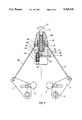
- FIG. 1 schematic cross section including a hydraulic brake in a first design form.
- FIG. 2 an enlarged cross section through a working cylinder in a second design form.
- a fork 1 of a bicycle is connected with a cross bar 32.
- a fastening hole 12 through which a screw (not shown in detail) grips and fastens the working cylinder 9 of the hydraulic brake.
- cantilever brake shoes 2 are, in a known fashion, swingably held in the pivot positions 3 and are provided with brake blocks 4.
- the brake blocks 4 work in a known fashion on the wheel rim 5 of either a front or rear tire.
- a penetrating traction cable 7 is inserted at the free swingable ends of the brake shoes 2, at which an end of a penetrating traction cable 7 is inserted.
- This traction cable 7 is directed over an operating head of the hydraulic brake which, in the form of FIG. 1, is constructed as a regulating wheel 20.
- the regulating wheel 20 has a lower threaded stem 19, which is screwed into a corresponding hole 18 of a main piston 10.
- the main piston 10 is sealed by an O-ring 13 in the chamber 15 of the working cylinder 9, and is moveable therein, under the influence of the hydraulic fluid.
- a support 8 is secured to the working cylinder 9, providing mutual connection in the region of a threaded hole 21.
- the hydraulic fluid is thereby directed by means of a hydraulic tube 22, which is fastened at the support 8 by means of a hose clamp screw 11.
- the hose clamp screw 1I closes up the hydraulic tube by means of a cone opposite the support 8.
- the hydraulic tube 22 feeds into a channel 14, the latter feeding into the chamber 15.
- the channel 14 leads to a filler nipple 16, which on its upper side is provided with a spring loaded closing ball 17.
- the hydraulic pressure is generated by a master cylinder 23 in which a master piston 24 is movably housed, and closed off with an O-ring.
- the master piston 23 has a hole 29 in which the end of a master piston rod 28 adjustably fits.
- This master piston rod 28 is constructed as a thread screw and is adjustably held in a threaded nut 30 which is turnably arranged in the moveable part of a brake lever 27.
- the brake lever 27 is swingably housed in a drag bearing 45 in a main housing 46, and the master piston rod 28 activates the master piston 24 in the master cylinder 23.
- the hydraulic tube 22 is fastened and closed off by a hose clamp screw 26 at the main housing 46.
- the main housing 46 is fastened by a hose clamp 34 on the steering column 33 of the bicycle.
- the master piston 24 By activating the brake lever 27 the master piston 24 (FIG. 1) is thereby moved to the left, and the pressure in the chamber of the master cylinder 23 increases and is instantaneously directed through the hydraulic tube 22 into the chamber 15 of the working cylinder 9. Thereby the main piston 10 is pushed upward and thereby also the activating head, which is constructed as the regulating wheel 20. Thereby the traction cable 7 is simultaneously activated.
- the cantilever brake shoes 2 with the related parts (brake block 4, pivot element) are retained and need not be replaced with other parts.
- the regulating wheel 20 can be activated after lifting the traction cable 7, whereupon the traction cable is thereafter again laid on the regulating wheel 20.
- hydraulic fluid is injected into the pressureless system through the screwed in filler nipple 16 over the closing ball 17, after opening the vent screw 25.
- the filling of the system is continued so long as hydraulic fluid exits out of the vent screw 25, and thereafter the operator closes the vent screw.
- the working cylinder 9 has a similar main piston 10, but this main piston is provided with a different operating head.
- the operating head is here constructed as a suspension stirrup 36, to which traction cables 35 are coupled.
- the traction cables 35 are of secure, constant length and are thereby symmetrically activated and again released.
- a regulating screw 37 is provided which is screwed into a threaded hole 31 of the suspension stirrup 36 and which supports itself with its stud-sided ends on the upper side of the main piston 10.
- a further pressure regulating channel 38 is present, which feeds into a chamber 47 in the support 41.
- a pressure regulating piston 39 is arranged in a manner that it can be moved and closed, and is engaged by a compression spring 43.
- the compression spring is supported with one end against the pressure regulating piston 39 and with its other end against a regulating screw 44.
- a rotary element or plunger 40 is movably arranged in a hole 48, and its stud-sided ends can be brought into connection with a snap ring groove 42 in the circumference of the pressure regulating piston 39. Thereby the displacement of the pressure regulating piston 39 can be arrested.
- a rotary element 40 is provided, which for example in wet weather is activated, whereby the pressure regulating piston 39 is arrested and the brake pressure works directly in the chamber 15 and thereby on the main piston 10.
- a further advantage of the invention in the use of a single working cylinder and a corresponding single main piston, lies primarily in that with use of the customary cantilever brakes, even changing the wheel is especially easy, which with the previously known hydraulic brakes, with which the main pistons were built directly in the brake saddle, was not possible. In those cases the brake saddle must be removed as well, which in not necessary with the device of the present invention.
- the operating head 20, 36 additionally shows lateral flange regions 49, which overlap the working cylinder 9 from above and so protect it against dirt.
Landscapes
- Engineering & Computer Science (AREA)
- Mechanical Engineering (AREA)
- Physics & Mathematics (AREA)
- Fluid Mechanics (AREA)
- Braking Arrangements (AREA)
- Transmission Of Braking Force In Braking Systems (AREA)
Applications Claiming Priority (2)
| Application Number | Priority Date | Filing Date | Title |
|---|---|---|---|
| DE4237110A DE4237110A1 (de) | 1992-11-03 | 1992-11-03 | Hydraulische Bremse für Fahrräder |
| DE4237110 | 1992-11-03 |
Publications (1)
| Publication Number | Publication Date |
|---|---|
| US5368136A true US5368136A (en) | 1994-11-29 |
Family
ID=6472001
Family Applications (1)
| Application Number | Title | Priority Date | Filing Date |
|---|---|---|---|
| US08/147,158 Expired - Fee Related US5368136A (en) | 1992-11-03 | 1993-11-03 | Hydraulic brakes for bicycles |
Country Status (4)
| Country | Link |
|---|---|
| US (1) | US5368136A (de) |
| EP (1) | EP0596335A1 (de) |
| JP (1) | JPH072160A (de) |
| DE (1) | DE4237110A1 (de) |
Cited By (15)
| Publication number | Priority date | Publication date | Assignee | Title |
|---|---|---|---|---|
| US5464239A (en) * | 1993-08-28 | 1995-11-07 | Fichtel & Sachs Ag | Bicycle, and a bicycle having a hydraulic brake, and an actuator for a hydraulic brake on a bicycle |
| US5505105A (en) * | 1995-02-17 | 1996-04-09 | Kuo; Yung-Pin | Connector for engaging brake cables |
| US5540304A (en) * | 1993-06-24 | 1996-07-30 | Hawkins; Rollin D. | Single-handled vehicle brake system |
| US5560260A (en) * | 1995-02-17 | 1996-10-01 | Kuo; Yung-Pin | Connector for engaging brake cables |
| US5678665A (en) * | 1995-11-22 | 1997-10-21 | Moldex Plastics & Tool Inc. | Hydraulic brake system |
| US5732601A (en) * | 1996-10-17 | 1998-03-31 | Wu; Chin-Chang | Coupling device for brake cables of bicycles |
| US5775466A (en) * | 1996-10-04 | 1998-07-07 | Banyas; Michael | Bicycle braking system |
| US20020187867A1 (en) * | 2001-06-07 | 2002-12-12 | Shimano Inc. | Hydraulic gear shift mechanism |
| US6553862B1 (en) * | 2000-05-19 | 2003-04-29 | Steven L. Caple | Emergency brake lever |
| US20040082122A1 (en) * | 2001-09-07 | 2004-04-29 | Power Integrations, Inc. | Method of fabricating a high-voltage transistor with a multi-layered extended drain structure |
| US20110011683A1 (en) * | 2009-07-17 | 2011-01-20 | Shimano, Inc. | Hydraulic Caliper Brake For A Bicycle |
| US20140041971A1 (en) * | 2011-04-19 | 2014-02-13 | Gustav Magenwirth Gmbh & Co. Kg | Brake and Method for the Installation Thereof |
| US20160251054A1 (en) * | 2015-02-27 | 2016-09-01 | Shimano Inc. | Bicycle brake device |
| US9764794B2 (en) | 2015-02-27 | 2017-09-19 | Shimano Inc. | Bicycle brake device and bicycle rim brake device |
| US20180306254A1 (en) * | 2015-11-25 | 2018-10-25 | Saf-Holland Gmbh | Actuation mechanism for a brake |
Families Citing this family (8)
| Publication number | Priority date | Publication date | Assignee | Title |
|---|---|---|---|---|
| DE4241521A1 (de) * | 1992-12-10 | 1994-06-16 | Fichtel & Sachs Ag | Hydraulische Betätigungseinrichtung für Bremsen und Schaltungen an Fahrrädern oder dergleichen |
| DE4430873C1 (de) * | 1994-08-31 | 1996-02-29 | Dietrich Gerhard Ellsaeser | Hydraulisch betätigtes Felgenbremssystem für Fahrräder |
| DE102009049164A1 (de) | 2009-10-12 | 2011-04-28 | Süle, Sandor | Vorrichtung zum Abbremsen eines Rades |
| DE102011075186A1 (de) * | 2011-05-03 | 2012-11-08 | Gustav Magenwirth Gmbh & Co. Kg | Geber für ein hydraulisches Betätigungselement |
| CN106585779A (zh) * | 2017-02-15 | 2017-04-26 | 北京骑骑智享科技发展有限公司 | 车锁及自行车 |
| DE102021107299A1 (de) | 2021-03-24 | 2022-09-29 | Schaeffler Technologies AG & Co. KG | Bremshebelanordnung für eine Bremsvorrichtung, Fahrzeug mit der Bremshebelanordnung sowie Bremshebelsatz |
| DE102021108983A1 (de) | 2021-04-12 | 2022-10-13 | Schaeffler Technologies AG & Co. KG | Bremshebelanordnung für eine Bremsvorrichtung sowie Fahrzeug mit der Bremshebelanordnung |
| KR102355279B1 (ko) * | 2021-07-23 | 2022-02-09 | 이규용 | 유압 브레이크의 순차 제동장치 |
Citations (13)
| Publication number | Priority date | Publication date | Assignee | Title |
|---|---|---|---|---|
| US3338337A (en) * | 1965-12-15 | 1967-08-29 | Elmer E Freeland | Hydraulic cycle brake |
| US3899057A (en) * | 1972-01-25 | 1975-08-12 | Dba Sa | Hydraulic control circuit |
| US3899056A (en) * | 1973-04-30 | 1975-08-12 | Carl L Doerr | Hydraulic bicycle brake assembly |
| US3921764A (en) * | 1973-07-25 | 1975-11-25 | William R Mathauser | Self-energizing bicycle brake |
| US3993174A (en) * | 1973-12-06 | 1976-11-23 | Lynn A. Williams Engineering Company | Hydraulic bicycle brake system |
| US4175648A (en) * | 1977-10-20 | 1979-11-27 | Sandor Sule | Device for the braking of bicycles |
| US4391353A (en) * | 1981-01-23 | 1983-07-05 | Mathauser William R | Hand operated hydraulic bicycle brake |
| US4483421A (en) * | 1982-02-05 | 1984-11-20 | Kennelly Kenneth M | Vacuum/hydraulic control system for speed synchronization of a pair of shafts |
| DE3325970A1 (de) * | 1983-07-19 | 1985-01-31 | Gustav Magenwirth Gmbh & Co, 7432 Urach | Hydraulisch betaetigte felgenbremse |
| DE3416726A1 (de) * | 1984-05-07 | 1985-11-07 | Sandor Thayngen Süle | Vorrichtung zum bremsen eines zweirades, insbesondere fahrradbremse |
| US4585094A (en) * | 1983-10-05 | 1986-04-29 | Gustav Magenwirth Gmbh & Co. | Hydraulic rim brake for bicycles |
| US4615415A (en) * | 1983-03-23 | 1986-10-07 | Mathauser William R | Hand operated hydraulic bicycle brake |
| US4632225A (en) * | 1985-05-08 | 1986-12-30 | Mathauser William R | Brake device for bicycles |
Family Cites Families (5)
| Publication number | Priority date | Publication date | Assignee | Title |
|---|---|---|---|---|
| BE444476A (de) * | ||||
| FR395042A (fr) * | 1908-08-14 | 1909-02-08 | Emile Clergue | Frein à liquide |
| CH234811A (de) * | 1941-10-01 | 1944-10-31 | Wittner Rudolf | Metronom. |
| FR2575991B1 (fr) * | 1985-01-11 | 1987-10-30 | Leleu Jean | Frein hydraulique pour bicyclettes et vehicules legers |
| GB8727123D0 (en) * | 1987-11-19 | 1987-12-23 | Marshall H R P | Pneumatic system |
-
1992
- 1992-11-03 DE DE4237110A patent/DE4237110A1/de not_active Withdrawn
-
1993
- 1993-10-21 EP EP93117021A patent/EP0596335A1/de not_active Withdrawn
- 1993-11-03 US US08/147,158 patent/US5368136A/en not_active Expired - Fee Related
- 1993-11-04 JP JP5275566A patent/JPH072160A/ja active Pending
Patent Citations (13)
| Publication number | Priority date | Publication date | Assignee | Title |
|---|---|---|---|---|
| US3338337A (en) * | 1965-12-15 | 1967-08-29 | Elmer E Freeland | Hydraulic cycle brake |
| US3899057A (en) * | 1972-01-25 | 1975-08-12 | Dba Sa | Hydraulic control circuit |
| US3899056A (en) * | 1973-04-30 | 1975-08-12 | Carl L Doerr | Hydraulic bicycle brake assembly |
| US3921764A (en) * | 1973-07-25 | 1975-11-25 | William R Mathauser | Self-energizing bicycle brake |
| US3993174A (en) * | 1973-12-06 | 1976-11-23 | Lynn A. Williams Engineering Company | Hydraulic bicycle brake system |
| US4175648A (en) * | 1977-10-20 | 1979-11-27 | Sandor Sule | Device for the braking of bicycles |
| US4391353A (en) * | 1981-01-23 | 1983-07-05 | Mathauser William R | Hand operated hydraulic bicycle brake |
| US4483421A (en) * | 1982-02-05 | 1984-11-20 | Kennelly Kenneth M | Vacuum/hydraulic control system for speed synchronization of a pair of shafts |
| US4615415A (en) * | 1983-03-23 | 1986-10-07 | Mathauser William R | Hand operated hydraulic bicycle brake |
| DE3325970A1 (de) * | 1983-07-19 | 1985-01-31 | Gustav Magenwirth Gmbh & Co, 7432 Urach | Hydraulisch betaetigte felgenbremse |
| US4585094A (en) * | 1983-10-05 | 1986-04-29 | Gustav Magenwirth Gmbh & Co. | Hydraulic rim brake for bicycles |
| DE3416726A1 (de) * | 1984-05-07 | 1985-11-07 | Sandor Thayngen Süle | Vorrichtung zum bremsen eines zweirades, insbesondere fahrradbremse |
| US4632225A (en) * | 1985-05-08 | 1986-12-30 | Mathauser William R | Brake device for bicycles |
Cited By (29)
| Publication number | Priority date | Publication date | Assignee | Title |
|---|---|---|---|---|
| US5540304A (en) * | 1993-06-24 | 1996-07-30 | Hawkins; Rollin D. | Single-handled vehicle brake system |
| US5538270A (en) * | 1993-08-28 | 1996-07-23 | Fichtel & Sachs Ag | Bicycle, and a bicycle having a hydraulic brake, and an actuator for a hydraulic brake on a bicycle |
| US5464239A (en) * | 1993-08-28 | 1995-11-07 | Fichtel & Sachs Ag | Bicycle, and a bicycle having a hydraulic brake, and an actuator for a hydraulic brake on a bicycle |
| US5505105A (en) * | 1995-02-17 | 1996-04-09 | Kuo; Yung-Pin | Connector for engaging brake cables |
| US5560260A (en) * | 1995-02-17 | 1996-10-01 | Kuo; Yung-Pin | Connector for engaging brake cables |
| US5678665A (en) * | 1995-11-22 | 1997-10-21 | Moldex Plastics & Tool Inc. | Hydraulic brake system |
| US5775466A (en) * | 1996-10-04 | 1998-07-07 | Banyas; Michael | Bicycle braking system |
| US5732601A (en) * | 1996-10-17 | 1998-03-31 | Wu; Chin-Chang | Coupling device for brake cables of bicycles |
| US6553862B1 (en) * | 2000-05-19 | 2003-04-29 | Steven L. Caple | Emergency brake lever |
| US7032475B2 (en) * | 2001-06-07 | 2006-04-25 | Shimano Inc. | Hydraulic gear shift mechanism |
| US7509888B2 (en) | 2001-06-07 | 2009-03-31 | Shimano Inc. | Hydraulic gear shift mechanism |
| US20070163378A1 (en) * | 2001-06-07 | 2007-07-19 | Shimano Inc. | Hydraulic gear shift mechanism |
| US20050155447A1 (en) * | 2001-06-07 | 2005-07-21 | Shimano Inc. | Hydraulic gear shift mechanism |
| US20050178233A1 (en) * | 2001-06-07 | 2005-08-18 | Shimano Inc. | Hydraulic gear shift mechanism |
| US20020187867A1 (en) * | 2001-06-07 | 2002-12-12 | Shimano Inc. | Hydraulic gear shift mechanism |
| US7137314B2 (en) | 2001-06-07 | 2006-11-21 | Shimano Inc | Hydraulic gear shift mechanism |
| US7219574B2 (en) | 2001-06-07 | 2007-05-22 | Shimano Inc. | Hydraulic gear shift mechanism |
| US6838346B2 (en) | 2001-09-07 | 2005-01-04 | Power Integrations, Inc. | Method of fabricating a high-voltage transistor with a multi-layered extended drain structure |
| US20040082122A1 (en) * | 2001-09-07 | 2004-04-29 | Power Integrations, Inc. | Method of fabricating a high-voltage transistor with a multi-layered extended drain structure |
| US20110011683A1 (en) * | 2009-07-17 | 2011-01-20 | Shimano, Inc. | Hydraulic Caliper Brake For A Bicycle |
| US8678144B2 (en) * | 2009-07-17 | 2014-03-25 | Shimano, Inc. | Hydraulic caliper brake for a bicycle |
| US20140041971A1 (en) * | 2011-04-19 | 2014-02-13 | Gustav Magenwirth Gmbh & Co. Kg | Brake and Method for the Installation Thereof |
| US9475541B2 (en) * | 2011-04-19 | 2016-10-25 | Gustav Magenwirth Gmbh & Co. Kg | Brake and method for the installation thereof |
| US9878760B2 (en) | 2011-04-19 | 2018-01-30 | Gustav Magenwirth Gmbh & Co. Kg | Brake and method for the installation thereof |
| US20160251054A1 (en) * | 2015-02-27 | 2016-09-01 | Shimano Inc. | Bicycle brake device |
| US9701362B2 (en) * | 2015-02-27 | 2017-07-11 | Shimano Inc. | Bicycle brake device |
| US9764794B2 (en) | 2015-02-27 | 2017-09-19 | Shimano Inc. | Bicycle brake device and bicycle rim brake device |
| US20180306254A1 (en) * | 2015-11-25 | 2018-10-25 | Saf-Holland Gmbh | Actuation mechanism for a brake |
| US10704622B2 (en) * | 2015-11-25 | 2020-07-07 | Saf-Holland Gmbh | Actuation mechanism for a brake |
Also Published As
| Publication number | Publication date |
|---|---|
| EP0596335A1 (de) | 1994-05-11 |
| JPH072160A (ja) | 1995-01-06 |
| DE4237110A1 (de) | 1994-05-05 |
Similar Documents
| Publication | Publication Date | Title |
|---|---|---|
| US5368136A (en) | Hydraulic brakes for bicycles | |
| US3776333A (en) | Bicycle brake arrangement | |
| US5813501A (en) | Hand operated hydraulic vehicle brake | |
| US6615955B2 (en) | Hydraulic brakes for bicycle | |
| US4057127A (en) | Safety actuating device adapted for two wheeled vehicles | |
| US4921081A (en) | Hydraulic brake apparatus for bicycles | |
| US6484855B1 (en) | Motor vehicle handlebars and hydraulic system therefor | |
| US5443134A (en) | Hydraulic actuating device for brakes and gearshifts of bicycles or the like | |
| US8459416B2 (en) | Quick-release apparatus for a bicycle hydraulic caliper brake | |
| CA2163475A1 (en) | Hydraulic brake system | |
| WO1994021510A1 (en) | An operating mechanism for a hydraulic master cylinder | |
| CN109383689B (zh) | 液压操作装置 | |
| US3899055A (en) | Brake actuating mechanism | |
| US3899056A (en) | Hydraulic bicycle brake assembly | |
| JPH10273087A (ja) | バーハンドル車両用ブレーキ装置 | |
| DE676964C (de) | Bremseinrichtung fuer Fahrzeuge, bei denen das Verhaeltnis der auf die Vorder- und Hinterraeder ausgeuebten Bremskraefte waehrend der Verzoegerung unter dem Einfluss einer traegen Masse geaendert wird | |
| US5615753A (en) | Brake assembly for a bicycle | |
| DE102021108983A1 (de) | Bremshebelanordnung für eine Bremsvorrichtung sowie Fahrzeug mit der Bremshebelanordnung | |
| CN217437688U (zh) | 一种用于叉车液压制动的调节装置 | |
| US4353570A (en) | Oil brake device for use in bicycles | |
| CN220577452U (zh) | 一种边斗摩托车的制动结构 | |
| DE102021107299A1 (de) | Bremshebelanordnung für eine Bremsvorrichtung, Fahrzeug mit der Bremshebelanordnung sowie Bremshebelsatz | |
| GB2234303A (en) | Vehicle braking circuit responsive to steering | |
| JPS5923667Y2 (ja) | 自転車のディスクブレ−キ装置 | |
| US5595425A (en) | Brake pressure control unit of vehicle load responsive type |
Legal Events
| Date | Code | Title | Description |
|---|---|---|---|
| FEPP | Fee payment procedure |
Free format text: PAYOR NUMBER ASSIGNED (ORIGINAL EVENT CODE: ASPN); ENTITY STATUS OF PATENT OWNER: SMALL ENTITY |
|
| REMI | Maintenance fee reminder mailed | ||
| LAPS | Lapse for failure to pay maintenance fees | ||
| FP | Lapsed due to failure to pay maintenance fee |
Effective date: 19981129 |
|
| STCH | Information on status: patent discontinuation |
Free format text: PATENT EXPIRED DUE TO NONPAYMENT OF MAINTENANCE FEES UNDER 37 CFR 1.362 |