US5356117A - Hollow trunnions for scissor jacks - Google Patents
Hollow trunnions for scissor jacks Download PDFInfo
- Publication number
- US5356117A US5356117A US08/084,129 US8412993A US5356117A US 5356117 A US5356117 A US 5356117A US 8412993 A US8412993 A US 8412993A US 5356117 A US5356117 A US 5356117A
- Authority
- US
- United States
- Prior art keywords
- trunnion
- lead screw
- pair
- channel members
- hollow
- Prior art date
- Legal status (The legal status is an assumption and is not a legal conclusion. Google has not performed a legal analysis and makes no representation as to the accuracy of the status listed.)
- Expired - Lifetime
Links
- 239000007787 solid Substances 0.000 claims abstract description 8
- 230000004048 modification Effects 0.000 abstract description 4
- 238000012986 modification Methods 0.000 abstract description 4
- 238000000034 method Methods 0.000 description 2
- 238000003466 welding Methods 0.000 description 2
- 239000002184 metal Substances 0.000 description 1
Images


Classifications
-
- B—PERFORMING OPERATIONS; TRANSPORTING
- B66—HOISTING; LIFTING; HAULING
- B66F—HOISTING, LIFTING, HAULING OR PUSHING, NOT OTHERWISE PROVIDED FOR, e.g. DEVICES WHICH APPLY A LIFTING OR PUSHING FORCE DIRECTLY TO THE SURFACE OF A LOAD
- B66F3/00—Devices, e.g. jacks, adapted for uninterrupted lifting of loads
- B66F3/08—Devices, e.g. jacks, adapted for uninterrupted lifting of loads screw operated
- B66F3/12—Devices, e.g. jacks, adapted for uninterrupted lifting of loads screw operated comprising toggle levers
Definitions
- This invention relates in general to scissors jacks and, in particular, to novel hollow trunnion designs.
- the improved hollow trunnions of the invention are substantially lighter than the solid trunnions of the prior art. They also result in less scrap and are less expensive than the prior art solid trunnions.
- the hollow trunnions of the present invention allow an assembled product such as a scissors jack to be lighter than prior art devices.
- Another feature of the hollow trunnion of the invention is to provide a flattened area on one side which serves as a bearing surface for a thrust bearing of the jack.
- hollow trunnion of the present invention provides for a hollow cylindrical trunnion member to which a bracket is connected that carries a threaded nut member so as to threadedly receive the screw of the jack.
- the hollow trunnion may be formed with spaces into which locking projections of the bracket may extend so as to assure alignment of the threaded opening in the screw with the openings through the hollow trunnion.
- It is a feature of the present invention is to provide lighter and simpler trunnions for jacks so as to decrease the weight of the jack and also to reduce the cost of the jack.
- FIG. 1 is a side plan view of a scissors jack with the hollow trunnions of the invention mounted therein;
- FIG. 2 is a perspective view of a hollow trunnion according to the invention.
- FIG. 3 is a perspective view of a modified form of the hollow trunnion of the invention.
- FIG. 4 is a sectional view illustrating the hollow trunnion of FIG. 3;
- FIG. 5 is a perspective view illustrating the hollow trunnion of FIG. 3;
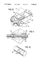
- FIG. 6 is a perspective view illustrating the modified hollow trunnion with a bracket which carries a threaded screw attached therethrough;
- FIG. 7 is a sectional view of the invention of FIG. 6;
- FIG. 8 is a detailed sectional view of the invention of FIG. 6;
- FIG. 9 is a perspective view of the hollow trunnion of FIG. 6;
- FIG. 10 illustrates a modified form of the invention
- FIG. 11 is a sectional view from FIG. 10.
- FIG. 12 illustrates a trunnion of the embodiment of FIG. 10.
- FIG. 1 illustrates a scissors jack with hollow trunnions of the invention mounted therein.
- a base 11 pivotally supports lower channel members 14 and 16 which are connected by pivot pins 12 and 13 to the base 11.
- a support 17 which has a vehicle engaging slot 18 is pivotally attached to upper channel members 22 and 23 by pivot pins 19 and 21.
- a hollow trunnion 34 according to the invention pivotally connects the upper end of the lower channel member 16 to the lower end of the upper channel member 23.
- the hollow trunnion member 34 is illustrated in perspective view in FIG. 2. It may be formed from a stamping which is formed into a hollow cylinder with the seam 38.
- FIGS. 3, 4 and 5 illustrate a modified form of the hollow trunnion 34.
- a flatted portion 42 is formed in the wall of the trunnion 40 adjacent an opening 43 for the lead screw 31.
- the bearing 32 is received against the flatted portion 42 as shown in FIGS. 4 and 5.
- the hollow trunnion 40 is formed with a seam 41 as illustrated.
- the ends 46 and 41 extend beyond the sides of the upper and lower channel members 23 and 16 as illustrated in FIG. 5.
- the threaded end 71 of the lead screw 31 passes through a hollow trunnion 61 shown in detail in FIG. 9 which has openings 68 and 69 for receiving the threaded end 71 of lead screw 31 therethrough.
- the lower ends of the upper channel member 22 and the upper ends of the lower channel member 14 are provided with openings through which the trunnion 61 extends as shown in FIG. 6.
- a U-shaped bracket 60 is formed with side legs 62 and 64 and an adjoining leg 63 which joins the legs 62 and 64. Openings 81 and 82 are formed in the end of legs 62 and 64 through which the hollow trunnion 61 extends as shown in FIG. 6.
- a threaded nut 66 is attached as by welding to the U-shaped bracket member 60 adjacent the cross-arm 63 as shown in FIGS. 6 and 7 and threadedly receives through the threaded opening 67 the threaded end 71 of the lead screw 31.
- the hollow trunnion member 61 is formed with a gap 73 into which extensions 74 formed on the side legs 62 and 64 of bracket 60 are received as shown in FIG. 8. This aligns the openings 68 and 69 with the opening 67 so that the lead screw 31 will pass therethrough as shown in FIG. 7.
- FIGS. 10, 11 and 12 illustrate a modified form of the invention somewhat similar to the embodiment shown in FIG. 6.
- a solid trunnion 141 extends through openings in channel members 14 and 22 and is formed with an opening 143 through which the lead screw 31 extends.
- a U-shaped bracket 160 has side legs 162 and 164 and an adjoining leg 163 which joins legs 162 and 164. Opening 181 and 182 are formed in the ends of legs 162 and 164 through which trunnion 141 extends.
- a threaded nut 166 is attached as by welding to U-shaped bracket 160 and threadedly receives the lead screw 31 therethrough.
- the threaded portion 71 of the lead screw 31 will cause the threaded nut 66 to move toward or away from the hexagonal head 33 raising or lowering the jack. If the jack is in the lowered position, the hexagonal nut 33 is rotated in a direction so as to cause the nut 66 to move toward the nut 33 thus raising the jack.
- Gear teeth 24 and 26, respectively, formed on the lower channel members 14 and 16 mesh with gear teeth 27 and 28 formed on the upper channel members 22 and 23 so as to raise and lower the jack.
Landscapes
- Life Sciences & Earth Sciences (AREA)
- Engineering & Computer Science (AREA)
- Geology (AREA)
- Mechanical Engineering (AREA)
- Structural Engineering (AREA)
- Transmission Devices (AREA)
Abstract
Description
Claims (5)
Priority Applications (1)
| Application Number | Priority Date | Filing Date | Title |
|---|---|---|---|
| US08/084,129 US5356117A (en) | 1993-07-01 | 1993-07-01 | Hollow trunnions for scissor jacks |
Applications Claiming Priority (1)
| Application Number | Priority Date | Filing Date | Title |
|---|---|---|---|
| US08/084,129 US5356117A (en) | 1993-07-01 | 1993-07-01 | Hollow trunnions for scissor jacks |
Publications (1)
| Publication Number | Publication Date |
|---|---|
| US5356117A true US5356117A (en) | 1994-10-18 |
Family
ID=22183057
Family Applications (1)
| Application Number | Title | Priority Date | Filing Date |
|---|---|---|---|
| US08/084,129 Expired - Lifetime US5356117A (en) | 1993-07-01 | 1993-07-01 | Hollow trunnions for scissor jacks |
Country Status (1)
| Country | Link |
|---|---|
| US (1) | US5356117A (en) |
Cited By (15)
| Publication number | Priority date | Publication date | Assignee | Title |
|---|---|---|---|---|
| US5529286A (en) * | 1994-05-10 | 1996-06-25 | Rikenkaki Kogyo Kabushiki Kaisha | Jack |
| US5692732A (en) * | 1995-11-07 | 1997-12-02 | Ventra Group Inc. | Tubular D-shaped trunnion |
| EP0896843A1 (en) * | 1997-08-11 | 1999-02-17 | Scambia Industrial Developments Aktiengesellschaft | Methods for manufacturing a pivot and a jack; a pivot and a jack |
| US6126132A (en) * | 1995-04-28 | 2000-10-03 | Lear Automotive Dearborn, Inc. | Multi-function single motor seat track actuator assembly |
| US6575432B1 (en) * | 1999-08-30 | 2003-06-10 | Batz, S., Coop. | Jack for vehicles |
| US6799749B1 (en) | 2003-12-15 | 2004-10-05 | Dura Global Technologies, Inc. | Slim pantograph jack |
| WO2005070812A1 (en) * | 2004-01-22 | 2005-08-04 | Thyssenkrupp Bilstein Gmbh | Jack |
| WO2006114071A1 (en) * | 2005-04-28 | 2006-11-02 | Thyssenkrupp Bilstein Wagenheber Gmbh | Guiding element for the spindle of a jack |
| CN100575238C (en) * | 2006-04-21 | 2009-12-30 | 郑元 | An electric scissor jack |
| US20110006273A1 (en) * | 2009-07-08 | 2011-01-13 | Shinn Fu Corporation | Scissor Jack |
| CN102431928A (en) * | 2011-11-24 | 2012-05-02 | 常熟通润汽车千斤顶有限公司 | Scissor jack with double-clamping-groove support |
| CN102606589A (en) * | 2012-03-13 | 2012-07-25 | 常州安协特种标准件有限公司 | Flat pin on jack for fixing screw |
| USD906623S1 (en) * | 2019-07-24 | 2020-12-29 | WeiFeng Liang | Scissor jack |
| JP2021066562A (en) * | 2019-10-24 | 2021-04-30 | 和光工業株式会社 | Pantograph jack |
| USD955084S1 (en) * | 2021-01-26 | 2022-06-14 | Ziwei LI | Cross base scissor jack |
Citations (3)
| Publication number | Priority date | Publication date | Assignee | Title |
|---|---|---|---|---|
| US4583713A (en) * | 1984-06-29 | 1986-04-22 | Aisin Seiki Kabushiki Kaisha | Pantograph jack apparatus |
| US4771986A (en) * | 1987-03-19 | 1988-09-20 | Michael Hung | Jack of a pantograph type (II) |
| US5117546A (en) * | 1991-06-17 | 1992-06-02 | Bethlehem Steel Corporation | Apparatus and method for replacing a bull gear on a trunnion |
-
1993
- 1993-07-01 US US08/084,129 patent/US5356117A/en not_active Expired - Lifetime
Patent Citations (3)
| Publication number | Priority date | Publication date | Assignee | Title |
|---|---|---|---|---|
| US4583713A (en) * | 1984-06-29 | 1986-04-22 | Aisin Seiki Kabushiki Kaisha | Pantograph jack apparatus |
| US4771986A (en) * | 1987-03-19 | 1988-09-20 | Michael Hung | Jack of a pantograph type (II) |
| US5117546A (en) * | 1991-06-17 | 1992-06-02 | Bethlehem Steel Corporation | Apparatus and method for replacing a bull gear on a trunnion |
Cited By (17)
| Publication number | Priority date | Publication date | Assignee | Title |
|---|---|---|---|---|
| US5529286A (en) * | 1994-05-10 | 1996-06-25 | Rikenkaki Kogyo Kabushiki Kaisha | Jack |
| CN1041297C (en) * | 1994-05-10 | 1998-12-23 | 理研化机工业株式会社 | Jack |
| US6126132A (en) * | 1995-04-28 | 2000-10-03 | Lear Automotive Dearborn, Inc. | Multi-function single motor seat track actuator assembly |
| US5692732A (en) * | 1995-11-07 | 1997-12-02 | Ventra Group Inc. | Tubular D-shaped trunnion |
| EP0896843A1 (en) * | 1997-08-11 | 1999-02-17 | Scambia Industrial Developments Aktiengesellschaft | Methods for manufacturing a pivot and a jack; a pivot and a jack |
| US6575432B1 (en) * | 1999-08-30 | 2003-06-10 | Batz, S., Coop. | Jack for vehicles |
| US6799749B1 (en) | 2003-12-15 | 2004-10-05 | Dura Global Technologies, Inc. | Slim pantograph jack |
| WO2005070812A1 (en) * | 2004-01-22 | 2005-08-04 | Thyssenkrupp Bilstein Gmbh | Jack |
| WO2006114071A1 (en) * | 2005-04-28 | 2006-11-02 | Thyssenkrupp Bilstein Wagenheber Gmbh | Guiding element for the spindle of a jack |
| DE102005020275A1 (en) * | 2005-04-28 | 2006-11-02 | Thyssenkrupp Bilstein Wagenheber Gmbh | Guiding element for spindle of jack for motor vehicle, has one-piece stamped and bent part formed with rounded areas and flattened section, and continuous slot extending in longitudinal direction and formed outside flattened section |
| CN100575238C (en) * | 2006-04-21 | 2009-12-30 | 郑元 | An electric scissor jack |
| US20110006273A1 (en) * | 2009-07-08 | 2011-01-13 | Shinn Fu Corporation | Scissor Jack |
| CN102431928A (en) * | 2011-11-24 | 2012-05-02 | 常熟通润汽车千斤顶有限公司 | Scissor jack with double-clamping-groove support |
| CN102606589A (en) * | 2012-03-13 | 2012-07-25 | 常州安协特种标准件有限公司 | Flat pin on jack for fixing screw |
| USD906623S1 (en) * | 2019-07-24 | 2020-12-29 | WeiFeng Liang | Scissor jack |
| JP2021066562A (en) * | 2019-10-24 | 2021-04-30 | 和光工業株式会社 | Pantograph jack |
| USD955084S1 (en) * | 2021-01-26 | 2022-06-14 | Ziwei LI | Cross base scissor jack |
Similar Documents
| Publication | Publication Date | Title |
|---|---|---|
| US5356117A (en) | Hollow trunnions for scissor jacks | |
| DE69835109T2 (en) | Lifting device with one articulated arm in the form of a double parallelogram | |
| DE19546233A1 (en) | Rod end bearing | |
| CN106494588B (en) | A kind of adjustable line style docking block suitable under various working | |
| DE29908098U1 (en) | Lifting device for a liquid crystal display device | |
| US5275378A (en) | Automotive jack | |
| EP0936176B1 (en) | Car jack | |
| DE2936002C2 (en) | ||
| DE3807759C2 (en) | ||
| EP0895832B1 (en) | A device for rotating at least one rotatable element and a method for manufacturing such a device | |
| AU600070B2 (en) | Method for forming a screw thread and tubular body with a screw thread | |
| GB2070560A (en) | Vehicle lifting jack | |
| US5692732A (en) | Tubular D-shaped trunnion | |
| EP1593644B1 (en) | Industrial truck with a piston-cylinder arrangement and an improved cylinder bearing | |
| EP1231356B1 (en) | Ladder with a level-compensating device | |
| DE1957184U (en) | TORSION BAR ARRANGEMENT ON MOTOR VEHICLES. | |
| EP0622328B1 (en) | Vehicle jack | |
| DE19953817C2 (en) | Jack with an insertion pin | |
| KR200205854Y1 (en) | Front frame support apparatus for vehicles | |
| DE2818537A1 (en) | ENERGY-ABSORBING RETURN DEVICE FOR A LIFTING CRANE | |
| DE19809441C2 (en) | Jack | |
| KR0125438Y1 (en) | Support rod fixing device of hydraulic press for disassembling fitted parts | |
| DE1119480B (en) | Mobile crane with a crane column that can be swiveled in vertical planes | |
| DE3043835C2 (en) | Device for internal deburring of welded pipes | |
| KR200150239Y1 (en) | Jack for car |
Legal Events
| Date | Code | Title | Description |
|---|---|---|---|
| AS | Assignment |
Owner name: UNIVERSAL TOOL & STAMPING COMPANY, INC., INDIANA Free format text: ASSIGNMENT OF ASSIGNORS INTEREST;ASSIGNOR:ENGEL, DARRYL L.;REEL/FRAME:006602/0133 Effective date: 19930610 |
|
| STPP | Information on status: patent application and granting procedure in general |
Free format text: APPLICATION UNDERGOING PREEXAM PROCESSING |
|
| FEPP | Fee payment procedure |
Free format text: PAYOR NUMBER ASSIGNED (ORIGINAL EVENT CODE: ASPN); ENTITY STATUS OF PATENT OWNER: LARGE ENTITY |
|
| FPAY | Fee payment |
Year of fee payment: 4 |
|
| AS | Assignment |
Owner name: BANK OF AMERICA NATIONAL TRUST AND SAVINGS ASSOCIA Free format text: SECURITY AGREEMENT;ASSIGNOR:UNIVERSAL TOOL & STAMPING COMPANY, INC;REEL/FRAME:009052/0399 Effective date: 19980309 |
|
| FPAY | Fee payment |
Year of fee payment: 8 |
|
| AS | Assignment |
Owner name: BANK OF AMERICA, N.A., AS COLLATERAL AGENT, WISCON Free format text: SECURITY INTEREST;ASSIGNOR:UNIVERSAL TOOL & STAMPING COMPANY, INC.;REEL/FRAME:016026/0236 Effective date: 20050503 |
|
| AS | Assignment |
Owner name: WILMINGTON TRUST COMPANY, AS COLLATERAL AGENT, DEL Free format text: SECURITY AGREEMENT;ASSIGNOR:UNIVERSAL TOOL AND STAMPING COMPANY, INC.;REEL/FRAME:016369/0273 Effective date: 20050628 |
|
| FPAY | Fee payment |
Year of fee payment: 12 |
|
| AS | Assignment |
Owner name: DURA OPERATING CORP., MICHIGAN Free format text: TERMINATION AND RELEASE;ASSIGNOR:GOLDMAN SACHS CREDIT PARTNERS, L.P., AS COLLATERAL AGRENT;REEL/FRAME:020478/0674 Effective date: 20080130 Owner name: UNIVERSAL TOOL & STAMPING COMPANY, INC., MICHIGAN Free format text: TERMINATION AND RELEASE;ASSIGNOR:GOLDMAN SACHS CREDIT PARTNERS, L.P., AS COLLATERAL AGRENT;REEL/FRAME:020478/0674 Effective date: 20080130 Owner name: DURA AUTOMOTIVE SYSTEMS CABLE OPERATIONS, INC., MI Free format text: TERMINATION AND RELEASE;ASSIGNOR:GOLDMAN SACHS CREDIT PARTNERS, L.P., AS COLLATERAL AGRENT;REEL/FRAME:020478/0674 Effective date: 20080130 Owner name: DURA GLOBAL TECHNOLOGIES, INC., MICHIGAN Free format text: TERMINATION AND RELEASE;ASSIGNOR:GOLDMAN SACHS CREDIT PARTNERS, L.P., AS COLLATERAL AGRENT;REEL/FRAME:020478/0674 Effective date: 20080130 Owner name: ATWOOD MOBILE PRODUCTS, INC., MICHIGAN Free format text: TERMINATION AND RELEASE;ASSIGNOR:GOLDMAN SACHS CREDIT PARTNERS, L.P., AS COLLATERAL AGRENT;REEL/FRAME:020478/0674 Effective date: 20080130 Owner name: DURA AUTOMOTIVE SYSTEMS, INC., MICHIGAN Free format text: TERMINATION AND RELEASE;ASSIGNOR:GOLDMAN SACHS CREDIT PARTNERS, L.P., AS COLLATERAL AGRENT;REEL/FRAME:020478/0674 Effective date: 20080130 Owner name: DURA OPERATING CORP.,MICHIGAN Free format text: TERMINATION AND RELEASE;ASSIGNOR:GOLDMAN SACHS CREDIT PARTNERS, L.P., AS COLLATERAL AGRENT;REEL/FRAME:020478/0674 Effective date: 20080130 Owner name: UNIVERSAL TOOL & STAMPING COMPANY, INC.,MICHIGAN Free format text: TERMINATION AND RELEASE;ASSIGNOR:GOLDMAN SACHS CREDIT PARTNERS, L.P., AS COLLATERAL AGRENT;REEL/FRAME:020478/0674 Effective date: 20080130 Owner name: DURA AUTOMOTIVE SYSTEMS CABLE OPERATIONS, INC.,MIC Free format text: TERMINATION AND RELEASE;ASSIGNOR:GOLDMAN SACHS CREDIT PARTNERS, L.P., AS COLLATERAL AGRENT;REEL/FRAME:020478/0674 Effective date: 20080130 Owner name: DURA GLOBAL TECHNOLOGIES, INC.,MICHIGAN Free format text: TERMINATION AND RELEASE;ASSIGNOR:GOLDMAN SACHS CREDIT PARTNERS, L.P., AS COLLATERAL AGRENT;REEL/FRAME:020478/0674 Effective date: 20080130 Owner name: ATWOOD MOBILE PRODUCTS, INC.,MICHIGAN Free format text: TERMINATION AND RELEASE;ASSIGNOR:GOLDMAN SACHS CREDIT PARTNERS, L.P., AS COLLATERAL AGRENT;REEL/FRAME:020478/0674 Effective date: 20080130 Owner name: DURA AUTOMOTIVE SYSTEMS, INC.,MICHIGAN Free format text: TERMINATION AND RELEASE;ASSIGNOR:GOLDMAN SACHS CREDIT PARTNERS, L.P., AS COLLATERAL AGRENT;REEL/FRAME:020478/0674 Effective date: 20080130 |
|
| AS | Assignment |
Owner name: AUTOLINE INDUSTRIES INDIANA, LLC, MICHIGAN Free format text: ASSIGNMENT OF ASSIGNORS INTEREST;ASSIGNOR:UNIVERSAL TOOL & STAMPING CO., INC.;REEL/FRAME:020609/0392 Effective date: 20071203 |
|
| AS | Assignment |
Owner name: AUTOLINE INDUSTRIES INDIANA, LLC, MICHIGAN Free format text: RELEASE OF LIEND, CLAIMS, INTERESTS AND ENCUMBRANCES;ASSIGNORS:ADWEST ELECTRONICS INC.;ATWOOD AUTOMOTIVE, INC.;ATWOOD MOBILE PRODUCTS, INC.;AND OTHERS;REEL/FRAME:020733/0318 Effective date: 20071204 |