US5331258A - Synchronous-rectification type control for direct current motors and method of making - Google Patents
Synchronous-rectification type control for direct current motors and method of making Download PDFInfo
- Publication number
- US5331258A US5331258A US07/859,226 US85922692A US5331258A US 5331258 A US5331258 A US 5331258A US 85922692 A US85922692 A US 85922692A US 5331258 A US5331258 A US 5331258A
- Authority
- US
- United States
- Prior art keywords
- motor
- control
- field effect
- effect transistors
- signal
- Prior art date
- Legal status (The legal status is an assumption and is not a legal conclusion. Google has not performed a legal analysis and makes no representation as to the accuracy of the status listed.)
- Expired - Lifetime
Links
Images


Classifications
-
- H—ELECTRICITY
- H02—GENERATION; CONVERSION OR DISTRIBUTION OF ELECTRIC POWER
- H02P—CONTROL OR REGULATION OF ELECTRIC MOTORS, ELECTRIC GENERATORS OR DYNAMO-ELECTRIC CONVERTERS; CONTROLLING TRANSFORMERS, REACTORS OR CHOKE COILS
- H02P7/00—Arrangements for regulating or controlling the speed or torque of electric DC motors
- H02P7/06—Arrangements for regulating or controlling the speed or torque of electric DC motors for regulating or controlling an individual DC dynamo-electric motor by varying field or armature current
- H02P7/18—Arrangements for regulating or controlling the speed or torque of electric DC motors for regulating or controlling an individual DC dynamo-electric motor by varying field or armature current by master control with auxiliary power
- H02P7/24—Arrangements for regulating or controlling the speed or torque of electric DC motors for regulating or controlling an individual DC dynamo-electric motor by varying field or armature current by master control with auxiliary power using discharge tubes or semiconductor devices
- H02P7/28—Arrangements for regulating or controlling the speed or torque of electric DC motors for regulating or controlling an individual DC dynamo-electric motor by varying field or armature current by master control with auxiliary power using discharge tubes or semiconductor devices using semiconductor devices
- H02P7/285—Arrangements for regulating or controlling the speed or torque of electric DC motors for regulating or controlling an individual DC dynamo-electric motor by varying field or armature current by master control with auxiliary power using discharge tubes or semiconductor devices using semiconductor devices controlling armature supply only
- H02P7/29—Arrangements for regulating or controlling the speed or torque of electric DC motors for regulating or controlling an individual DC dynamo-electric motor by varying field or armature current by master control with auxiliary power using discharge tubes or semiconductor devices using semiconductor devices controlling armature supply only using pulse modulation
-
- B—PERFORMING OPERATIONS; TRANSPORTING
- B60—VEHICLES IN GENERAL
- B60L—PROPULSION OF ELECTRICALLY-PROPELLED VEHICLES; SUPPLYING ELECTRIC POWER FOR AUXILIARY EQUIPMENT OF ELECTRICALLY-PROPELLED VEHICLES; ELECTRODYNAMIC BRAKE SYSTEMS FOR VEHICLES IN GENERAL; MAGNETIC SUSPENSION OR LEVITATION FOR VEHICLES; MONITORING OPERATING VARIABLES OF ELECTRICALLY-PROPELLED VEHICLES; ELECTRIC SAFETY DEVICES FOR ELECTRICALLY-PROPELLED VEHICLES
- B60L50/00—Electric propulsion with power supplied within the vehicle
- B60L50/50—Electric propulsion with power supplied within the vehicle using propulsion power supplied by batteries or fuel cells
- B60L50/52—Electric propulsion with power supplied within the vehicle using propulsion power supplied by batteries or fuel cells characterised by DC-motors
-
- B—PERFORMING OPERATIONS; TRANSPORTING
- B60—VEHICLES IN GENERAL
- B60L—PROPULSION OF ELECTRICALLY-PROPELLED VEHICLES; SUPPLYING ELECTRIC POWER FOR AUXILIARY EQUIPMENT OF ELECTRICALLY-PROPELLED VEHICLES; ELECTRODYNAMIC BRAKE SYSTEMS FOR VEHICLES IN GENERAL; MAGNETIC SUSPENSION OR LEVITATION FOR VEHICLES; MONITORING OPERATING VARIABLES OF ELECTRICALLY-PROPELLED VEHICLES; ELECTRIC SAFETY DEVICES FOR ELECTRICALLY-PROPELLED VEHICLES
- B60L2220/00—Electrical machine types; Structures or applications thereof
- B60L2220/10—Electrical machine types
- B60L2220/14—Synchronous machines
-
- Y—GENERAL TAGGING OF NEW TECHNOLOGICAL DEVELOPMENTS; GENERAL TAGGING OF CROSS-SECTIONAL TECHNOLOGIES SPANNING OVER SEVERAL SECTIONS OF THE IPC; TECHNICAL SUBJECTS COVERED BY FORMER USPC CROSS-REFERENCE ART COLLECTIONS [XRACs] AND DIGESTS
- Y02—TECHNOLOGIES OR APPLICATIONS FOR MITIGATION OR ADAPTATION AGAINST CLIMATE CHANGE
- Y02T—CLIMATE CHANGE MITIGATION TECHNOLOGIES RELATED TO TRANSPORTATION
- Y02T10/00—Road transport of goods or passengers
- Y02T10/60—Other road transportation technologies with climate change mitigation effect
- Y02T10/64—Electric machine technologies in electromobility
-
- Y—GENERAL TAGGING OF NEW TECHNOLOGICAL DEVELOPMENTS; GENERAL TAGGING OF CROSS-SECTIONAL TECHNOLOGIES SPANNING OVER SEVERAL SECTIONS OF THE IPC; TECHNICAL SUBJECTS COVERED BY FORMER USPC CROSS-REFERENCE ART COLLECTIONS [XRACs] AND DIGESTS
- Y02—TECHNOLOGIES OR APPLICATIONS FOR MITIGATION OR ADAPTATION AGAINST CLIMATE CHANGE
- Y02T—CLIMATE CHANGE MITIGATION TECHNOLOGIES RELATED TO TRANSPORTATION
- Y02T10/00—Road transport of goods or passengers
- Y02T10/60—Other road transportation technologies with climate change mitigation effect
- Y02T10/70—Energy storage systems for electromobility, e.g. batteries
-
- Y—GENERAL TAGGING OF NEW TECHNOLOGICAL DEVELOPMENTS; GENERAL TAGGING OF CROSS-SECTIONAL TECHNOLOGIES SPANNING OVER SEVERAL SECTIONS OF THE IPC; TECHNICAL SUBJECTS COVERED BY FORMER USPC CROSS-REFERENCE ART COLLECTIONS [XRACs] AND DIGESTS
- Y02—TECHNOLOGIES OR APPLICATIONS FOR MITIGATION OR ADAPTATION AGAINST CLIMATE CHANGE
- Y02T—CLIMATE CHANGE MITIGATION TECHNOLOGIES RELATED TO TRANSPORTATION
- Y02T10/00—Road transport of goods or passengers
- Y02T10/80—Technologies aiming to reduce greenhouse gasses emissions common to all road transportation technologies
- Y02T10/92—Energy efficient charging or discharging systems for batteries, ultracapacitors, supercapacitors or double-layer capacitors specially adapted for vehicles
-
- Y—GENERAL TAGGING OF NEW TECHNOLOGICAL DEVELOPMENTS; GENERAL TAGGING OF CROSS-SECTIONAL TECHNOLOGIES SPANNING OVER SEVERAL SECTIONS OF THE IPC; TECHNICAL SUBJECTS COVERED BY FORMER USPC CROSS-REFERENCE ART COLLECTIONS [XRACs] AND DIGESTS
- Y10—TECHNICAL SUBJECTS COVERED BY FORMER USPC
- Y10S—TECHNICAL SUBJECTS COVERED BY FORMER USPC CROSS-REFERENCE ART COLLECTIONS [XRACs] AND DIGESTS
- Y10S388/00—Electricity: motor control systems
- Y10S388/907—Specific control circuit element or device
Definitions
- the present invention relates to direct current motor control systems used in controlling the rotational speed of traction motors for battery-powered vehicles and, in particular, to a novel DC motor control topology and structure.
- control systems which currently dominate the battery-powered direct current motor market fall into two principal categories, control systems which use silicon controlled rectifiers and those which use metal-oxide-semiconductor field effect translators for switching DC current to control motor speed.
- Silicon controlled rectifiers are commonly employed in heavy equipment control devices for providing a variable mark-space ratio power regulator responsive to a motor current command signal.
- SCR controllers have been widely accepted and are proven to be reliable in most operating conditions.
- SCR controllers do have disadvantages, however.
- SGR controllers are physically bulky and massive. They are also known to dissipate substantial amounts of energy and they are not well suited for automated assembly techniques.
- SCR devices are readily switched on extra commutation circuitry is required to switch them off.
- a further problem with SCR controllers is that the commutation frequency of those controllers is in the audible range, commonly at 2000 Hz or less. During operation, SGR controllers therefore tend to emit an audible hum and a poorly designed SCR controller can emit noise which humans find irritating and fatiguing.
- MOSFET metal-oxide-semiconductor field effect transistor
- MOSFETs are advantageous because they have a high input impedance, low energy dissipation and are readily switched from a conductive to a nonconductive state without additional circuitry. MOSFETs are also advantageous because they are small devices that are well suited for use with automated assembly techniques. They are further advantageous because the per unit cost of the device is rapidly decreasing as a result of utilization in a wide range of consumer, industrial and automotive applications. MOSFETs are also switchable at frequencies which are at the limit of, or beyond the audible range for humans so that MOSFET controllers reduce or eliminate controller-generated audible noise.
- PWM motor controllers include free-wheeling diodes for commuting armature current generated by a motor during periods of operation when the battery current is switched off. Without free-wheeling diodes, the voltage transient generated by the armature when the switching device opens would destroy the control. Although free-wheeling diodes are effective for communicating those currents, they have the disadvantage of contributing to significant power losses through waste heat generation. For example, a forklift accelerating up a grade may require 500 A to the motor armature at a 20 percent PWM duty cycle.
- MOSFET controllers have not been used extensively in the Class 1 and Class 2 truck markets. MOSFET controllers have only seen reasonable acceptance in the smaller Class 3 Walk behind truck market and small electric vehicle markets, such as electric golf carts and light baggage carriers.
- a DC motor control in accordance with the invention introduce a technique hereinafter referred to as "synchronous-rectification” in which the free-wheeling diodes in prior art controllers are replaced with MOSFET devices.
- the synchronous rectification MOSFETs hereinafter referred to as “SR FETs” are switched on during intervals that free-wheeling diodes would be conducting. Since MOSFETs have a much lower forward voltage drop than free-wheeling diodes, the resulting control is significantly more efficient. In the example described above, free-wheeling diodes generate some 400 Watts while SR FETs under equivalent conditions generate only about 120 Watts. Consequently, synchronous-rectification significantly reduces controller heating during heavy lugging and prolonged acceleration. Synchronous-rectification controls are therefore capable of sustained high amperage throughputs and are suitable for use in Class 1 and 2 trucks as well as Class 3 trucks.
- the invention thus provides an electronic control for direct current traction motors comprising a first plurality of parallel-connected power field effect transistors arranged for connection in series with the motor, a field gate electrode of each first field effect transistor being connected to a common control line for controlling an on-off cycle of conduction through the first field effect transistors to provide drive current to the motor from a direct current source; and a second plurality or parallel connected power field effect transistors arranged for connection in parallel with the motor, a field gate electrode of each second field effect transistor being connected to a common control line for controlling a synchronous-rectification on-off cycle of conduction through the second field effect transistors for commuting the motor current when the first parallel connected field effect transistors are switched off.
- a physical structure for a direct current traction motor controller which includes a heat sink structure having a top surface; the top surface of the heat sink structure including at least two spaced-apart channels for receiving a first and second plurality of electronic components affixed to a circuit board positioned on the top surface; and, at least two elongated retainers respectively insertable in the channels while the electronic components are received therein, the retainers being movable after insertion in the channels to a disposition wherein they urge the respective first and second plurality of electronic components to a heat exchanging contact with a sidewall of the respective channels.
- This physical structure permits a high density packing of electronic components.
- the invention thus provides a novel energy-conserving control topology, and a novel physical structure for a DC motor controller which is more economically assembled and permits a higher packing density of components than prior art controls for motors of the same type.
- Synchronous-rectification type controls are suitable for use with series wound motors as well as separately excited motors. Although the description of the preferred embodiments which follows relates to series wound motors, the invention is in no way limited to series wound motors in its utility.
- FIG. 1 is a schematic diagram of the topology of an electronic control for a direct current traction motor in accordance with the invention
- FIG. 2 is a graph of the theoretical loss comparisons of a prior art MOSFET control which uses free-wheel diodes to commute motor current compared to a synchronous-rectification type control in accordance with the invention:
- FIG. 3 is a schematic diagram of the control logic circuit illustrating the relationship between the enable and pulse-width modulated signals input to the control logic circuit and the motor FET and SR FET output signals generated by the control logic circuit;
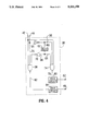
- FIG. 4 is a simplified schematic circuit diagram of a preferred embodiment of the control logic circuit in accordance with the invention.
- FIG. 5 is a cross-sectional view of a preferred physical structure for a controller in accordance with the invention.
- FIG. 1 shows a schematic diagram of a direct current motor system which includes an electronic control topology in accordance with the invention.
- the system includes a battery 20 and a series wound DC traction motor, generally referred to by reference 24 which includes an armature 26 and a field winding 28 having associated motor direction contactors 30, 31 for reversing a direction of a torque of the motor 24.
- the circuit is provided with a disconnect 22 used for disconnecting the battery from the motor.
- a fuse 32 protects the circuit from extreme current conditions which can arise, for instance, if short circuit condition develops in the system.
- Other details of the circuit are constructed in accordance with well-known electrical principles which are familiar to those skilled in the art.
- the electronic control in accordance with the invention includes that portion of the diagram in FIG. 1 surrounded by a dotted line.
- the control includes a microprocessor 34 which receives an input signal from an accelerator potentiometer 36.
- the microprocessor 34 processes the accelerator input and output signals to a control logic 38.
- Those signals include an enable signal 42 and a pulse-width modulated motor current command (PWM) signal 44.
- PWM pulse-width modulated motor current command
- Other variables which affect the microprocessor output on the enable line 42 and the PWM line 44 may include battery current, motor current, motor direction, battery voltage, control heat sink temperature, hydraulic pump status, and seat switch status if the control 33 is installed in a vehicle having an operator's seat.
- the plug-braking diode commutes armature current when the motor field is reversed for an operation known as "plug braking", commonly used to slow down an electric vehicle by reversing the polarity of the motor. It is hereinafter assumed that those skilled in the art of electronic controls are familiar with thealgorithms used to generate a PWM signal for controlling the current to a DC motor.
- a control logic circuit 38 drives the gate electrode of a plurality of motor MOSFETs 50, herein after referred to as "Motor FETs", and the gate electrodes of a plurality of synchronous-rectification MOSFETs 51, referred to as "SR FETs”, as noted above.
- Motor FETs 50 are switched on and off by the common control line 48 in an on-off cycle of conduction to provide drive current to the motor 24 from the battery 20.
- Motor FETs 50 are switched off, the motor 24 resists the decay ofcurrent on commutation of the supply current by the Motor FETs 50.
- reverse connected "free-wheeling" diodes have been parallel connected with the motor to commute the inductive load when the Motor FETs 50 are switched off.
- SR FETs 51 which are switched on whenMotor FETs 50 are switched off thus providing a path of conduction for the armature current of motor 24 as the current path through Motor FETs 50 is closed.
- the timing of the on-off cycle of Motor FETs 50 and SR FETs 51 is critical and shall be explained in more detail below in relation to FIGS. 3 and 4.
- the control in accordance with the invention also includes a plurality of capacitors 49, as is common in MOSFET controllers.
- the capacitors are preferably low equivalent-series-resistance, low inductance and high capacitance components which isolate the battery from the ripple current created by the switching cycle of the MOSFETs.
- FIG. 2 shows a graph of the theoretical loss comparisons for controllers based on a free-wheel diode control system as compared with a synchronous-rectification control system in accordance with the invention.
- the horizontal axis of the graph represents the percent duty cycle of the motor current drive signal. Duty cycle is a measure of the pulse width of the motor current drive signal. At a 100% duty cycle, the motor is connected to the battery via the Motor FETs 50 100% of the time, while at a 20% duty cycle the motor is connected to the battery 20% of the time.
- the vertical axis of the graph represents both the motor current in Ampe and the controller energy losses in Watts.
- FIG. 3 is a timing diagram illustrating the inputs and outputs of control logic circuit 38.
- the purpose of the control logic circuit 38 is to generate gate signals which turn the Motor FETs 50 on when the PWM is driven high and to turn the SR FETs 51 on when the Motor FETS 50 are off, thus preventing the Motor FETs 50 and SR FETS 51 from being simultaneouslyconductive.
- the control logic also receives an enable signal which permits microprocessor 34 (see FIG. 1) to turn off both the Motor FETs and the SR FETs if a fault condition is detected.
- microprocessor 34 outputs a PWM motor current command signal on PWM line 44 and an enable signal on enable line 42 to control logic circuit 38.
- Thecontrol logic circuit 38 outputs a Motor FET gate control signal on line 48and a SR FET gate control signal on line 52.
- the microprocessor 34 preferably outputs the PWM pulse at 20,000Hz, which is well within the operating limits of the Motor FETs 50 and the SR FETs 51.
- microprocessor 34 generates an enable signal and a PWM signal on lines 42 and 44 respectively.
- the enable signal is driven high at all times factors monitored by the microprocessor 34 indicate that the system is in a safe operating condition.
- the enable signal 88 is driven low to ensure that both Motor FETs and SR FETs are switched off whenever a parameter monitored by the microprocessor 34 indicates a system or operator malfunction. For instance, if a vehicle is equipped with a seat switch andthe operator leaves the seat of the vehicle for a predetermined length of time, the enable signal is driven low and the control logic cuts power to the drive motor 24 (see FIG.
- a PWM signal 90 is generated by the microprocessor 34 in response to an output of an accelerator potentiometer 36, as well as other variables monitored by the microprocessor and described above.
- a time delay 86 separates the periods when the Motor FETs 50 are switched on and the periods when the SR FETs 51 are switched on.
- the time delay 86 is necessary to accommodate the switching response time of the FET devices. Power FETs may take as long as 700 ns to switch fully off in response to a gate signal. Without time delay 86, a brief period would exist when the motor FETs 50 and SR FETs 51 were both conductive, resulting in large current surges. This delay is preferably a few tens of nanoseconds longer than the device switch response time of therespective FETs.
- FIG. 4 shows a schematic diagram of a preferred embodiment of the control logic circuit 38.
- the PWM line 44 and the enable line 42 transmit signals from the microprocessor 34 (see FIG. 1) to the control logic circuit 38.
- the PWM line 44 is connected to a first phase inverter 54 whose output is connected to an AND gate 74 by connection 56 and to a delay circuit 62 by connection 60.
- the delay circuit 62 may constitute any number of circuits that are capable of delaying an electrical pulse without undue distortion.Without the delay circuit 62, the drive circuits 80 and 84 for each of the Motor FETs and the SR FETs would be switched on almost simultaneously and would be mutually conductive for a brief period of time that would be adequate to short circuit the control system and cause damage to the electronic components of the controller.
- Delay circuit 62 must therefore delay a pulse by at least the device switch time of the FETs used in the control. Typically, a delay of about 750 nanoseconds is appropriate.
- the output of delay circuit 62 is connected by connection 64 to AND gate 74 and by connection 66 to a second phase inverter 70 which inverts the phaseof an electrical pulse to its original condition.
- the output of phase inverter 70 is connected to a second AND gate 58 which also receives pulsed signals directly from PWM line 44 via connection 76.
- the output of AND gate 58 is directed to a drive circuit 84 for the Motor FETs 50 by a connection 48.
- the output of AND gate 74 is connected by a connection 78 to a drive circuit 80 for the SR FETs 51.
- FIG. 5 shows a cross-sectional view of a preferred embodiment of a novel physical structure for a motor control in accordance with the invention.
- the physical structure for a motor controller in accordance with the invention provides an alternate method of ensuring heat conducting contact between the electronic switching components and the heat sink structure of a controller.
- the physical structure of a preferred embodiment of a motor controller includes a heat sink base 96.
- the base 96 has a top surface which includes a plurality of spaced apart channels 98 for receiving electronic switching components such as Motor FETs 50, SR FETs 51, plug brake diodes 46, and ancillary circuits. These electronic components are attached by their respective legs to a current control board 100 that is supported on the top surface of the heat sink base 96.
- Aplurality of power bar conductors 102 rest atop current control board 100. There are preferably five power bars 102 provided. Two power bars are connected to the opposite poles of the battery 20 (see FIG. 1).
- One power bar 102 is connected to the motor field 28, one power bar 102 is connectedto motor field/armature conjunction and one power bar 102 is connected to the motor armature 26.
- a capacitor board 104 rests atop the power bars 102and supports capacitors 48.
- capacitors 48 Preferably, low equivalent-series-resistance, low inductance high capacitance capacitors are connected in two rows of four capacitors each along opposite edges of the capacitor board 104.
- a microprocessor board 106 is supported on a top surface of capacitor board 104 between the opposite rows of capacitors 48. Microprocessor board 106 supports the microprocessor 34 and related circuitry.
- the electronic switching components are first connected to the circuit control board 100 by inserting their respective legs into preformed holes in the circuit board 100 but the legs are not soldered to the printed circuit at this stage of the process.
- Electronic components ofthe controller are electrically insulated from the heat sink base 96. It istherefore necessary to position electrically insulating/heat conducting sheets 108 between the components and the heat sink base 96.
- the insulating sheets 108 are generally made of a specifically formulated plastic polymer which readily conducts heat but not electricity.
- the insulating sheets 108 are well-known in the art and widely available. Because insulating sheet 108 is pliable, the electronic components must beinserted into channels 98 without making intimate contact with the sheets 108.
- each retainer member 110 is preferably a structurewith a dogleg-shaped cross-section made of a spring steel, or the like, each retainer member 110 is provided with registration tabs 101 which mates with alignment holes in the current control board 100.
- the insertionand positioning of retainer members 110 will be explained in more detail below in relation to FIG. 6. As is apparent, retainer members 110 exert a constant pressure to urge electrical components into contact with insulating sheets 108 for a direct heat conduction to the heat sink 96.
- the various components of the controller are locked in an assembled condition by screw fasteners or the like which pass through preformed holes in the circuit boards and engage appropriately positioned nuts 112 that slide in inverted T-shaped slots 114 which are machined between the channels 98 in the top surface of the heat sink base 96.
- FIG. 6 shows a detailed cross-sectional view of the electrical component fastening system in accordance with the invention.
- the channels 98 for receiving electrical components attached to the current control board 100 are preferably machined with two spaced apart parallel ridges 116 on a bottom surface of the channel.
- the retainer members 110 are slid into the channel with their bottom ends between the ridges 116.
- an elongated key having a triangular cross-section and a tapered front end (not illustrated) is inserted between the retainer members and guided by the channel formed by the ridges 116 to force the bottom edges of each retainer member over a corresponding ridge 116.
- the retainer member 110 shown on the left of FIG.6 has been forced over ridge 116 using the key 118.
- the opposite retainer member 110 on the right is shown in a relaxed condition.
- electrical components are quickly and easily locked in a heat exchanging relationship with the sides of channels 98 and the time consuming steps of drilling and tapping holes to receive screw fasteners for securing the components to the heat sink base 96 are completely eliminated.
- This technique also permits significantly higher component packing density because space for accommodating drilling, tapping and/or screw fastener driving equipment need not be provided.
- the legs of each component are soldered to the printed circuit and the remainder of the controller is assembled. This method permits the assembly of a DC motor controller in less time and at less expense than prior art methods.
Landscapes
- Engineering & Computer Science (AREA)
- Power Engineering (AREA)
- Mechanical Engineering (AREA)
- Sustainable Energy (AREA)
- Sustainable Development (AREA)
- Transportation (AREA)
- Life Sciences & Earth Sciences (AREA)
- Control Of Direct Current Motors (AREA)
- Control Of Ac Motors In General (AREA)
- Control Of Multiple Motors (AREA)
- Control Of Eletrric Generators (AREA)
- Electric Propulsion And Braking For Vehicles (AREA)
- Rectifiers (AREA)
Priority Applications (12)
| Application Number | Priority Date | Filing Date | Title |
|---|---|---|---|
| US07/859,226 US5331258A (en) | 1992-03-30 | 1992-03-30 | Synchronous-rectification type control for direct current motors and method of making |
| NZ251285A NZ251285A (en) | 1992-03-30 | 1993-03-30 | Field effect transistor controller for direct current motor |
| ES93907706T ES2107013T3 (es) | 1992-03-30 | 1993-03-30 | Control del tipo de rectificacion sincrona para motores de corriente continua. |
| EP93907706A EP0634064B1 (de) | 1992-03-30 | 1993-03-30 | Synchron-gleichrichtungs-regelung fuer gleichstrommotoren |
| AU38834/93A AU668552B2 (en) | 1992-03-30 | 1993-03-30 | Synchronous-rectification type control for direct current motors and method of making |
| AT93907706T ATE158451T1 (de) | 1992-03-30 | 1993-03-30 | Synchron-gleichrichtungs-regelung fuer gleichstrommotoren |
| CA002133469A CA2133469C (en) | 1992-03-30 | 1993-03-30 | Synchronous rectification type controller for direct current motors and method of making |
| DE69314019T DE69314019T2 (de) | 1992-03-30 | 1993-03-30 | Synchron-gleichrichtungs-regelung fuer gleichstrommotoren |
| PCT/CA1993/000131 WO1993020611A2 (en) | 1992-03-30 | 1993-03-30 | Synchronous-rectification type control for direct current motors and method of making |
| DK93907706.1T DK0634064T3 (da) | 1992-03-30 | 1993-03-30 | Styring af synkron-ensretningstypen for jævnstrømsmotorer |
| KR1019940703436A KR100275361B1 (ko) | 1992-03-30 | 1993-03-30 | 직류 모우터용 동기-정류 방식 제어기(synchronous-rectification type control for director current motors) |
| GR970403335T GR3025685T3 (en) | 1992-03-30 | 1997-12-16 | Synchronous-rectification type control for direct current motors and method of making. |
Applications Claiming Priority (1)
| Application Number | Priority Date | Filing Date | Title |
|---|---|---|---|
| US07/859,226 US5331258A (en) | 1992-03-30 | 1992-03-30 | Synchronous-rectification type control for direct current motors and method of making |
Publications (1)
| Publication Number | Publication Date |
|---|---|
| US5331258A true US5331258A (en) | 1994-07-19 |
Family
ID=25330389
Family Applications (1)
| Application Number | Title | Priority Date | Filing Date |
|---|---|---|---|
| US07/859,226 Expired - Lifetime US5331258A (en) | 1992-03-30 | 1992-03-30 | Synchronous-rectification type control for direct current motors and method of making |
Country Status (12)
| Country | Link |
|---|---|
| US (1) | US5331258A (de) |
| EP (1) | EP0634064B1 (de) |
| KR (1) | KR100275361B1 (de) |
| AT (1) | ATE158451T1 (de) |
| AU (1) | AU668552B2 (de) |
| CA (1) | CA2133469C (de) |
| DE (1) | DE69314019T2 (de) |
| DK (1) | DK0634064T3 (de) |
| ES (1) | ES2107013T3 (de) |
| GR (1) | GR3025685T3 (de) |
| NZ (1) | NZ251285A (de) |
| WO (1) | WO1993020611A2 (de) |
Cited By (21)
| Publication number | Priority date | Publication date | Assignee | Title |
|---|---|---|---|---|
| WO1997015111A3 (en) * | 1995-10-17 | 1997-06-05 | Fasco Industries | A brushless dc motor assembly |
| US5764009A (en) * | 1994-08-25 | 1998-06-09 | Yamaha Hatsudoki Kabushiki Kaisha | Motor control device in electric motor-operated vehicle |
| US5886487A (en) * | 1997-04-29 | 1999-03-23 | Unitrode Corporation | DC motor driver having output FETS that conduct to rectify output overvoltage and undervoltage transients |
| US5896487A (en) * | 1996-03-05 | 1999-04-20 | Masten; Billy Reese | Opto-electrically controlled direct current motor speed control circuit |
| US6000486A (en) * | 1997-04-18 | 1999-12-14 | Medicart, L.L.C. | Apparatus for providing self-propelled motion to medication carts |
| EP0982174A1 (de) * | 1998-08-28 | 2000-03-01 | Alstom France SA | Verbesserte Anordnung zur Stromversorgung Antriebsmotoren für Nahverkehrfahrzeuge |
| US6226582B1 (en) | 1997-07-21 | 2001-05-01 | Sre Controls, Inc. | Integrated control for electric lift trucks |
| US6255789B1 (en) * | 1999-02-04 | 2001-07-03 | Matsushita Electric Industrial Co., Ltd. | Motor |
| US6538405B1 (en) * | 2000-04-28 | 2003-03-25 | The Cherry Corporation | Accessory control system |
| US20030080709A1 (en) * | 1998-08-14 | 2003-05-01 | Jorg Hornberger | Arrangement with an electric motor |
| US6652249B2 (en) * | 1999-12-13 | 2003-11-25 | Parker-Hannifin Corporation | Brushless DC wet motor fuel pump with integral controller |
| US20040227471A1 (en) * | 2003-04-30 | 2004-11-18 | Ribarich Thomas J. | Hybrid ballast control circuit in a simplified package |
| US6825625B1 (en) | 1998-06-13 | 2004-11-30 | Ebm-Papst St. Georgen Gmbh & Co. Kg | Device with an electromotor |
| US20050284448A1 (en) * | 2004-06-23 | 2005-12-29 | Forgue John R | Fuel pump system |
| US20060049788A1 (en) * | 2004-09-07 | 2006-03-09 | Mitsubishi Denki Kabushiki Kaisha | Electric power steering controller |
| US20070144310A1 (en) * | 2005-11-04 | 2007-06-28 | Credo Technology Corporation | Articulating drill with integrated circuit board and method of operation |
| US20100195360A1 (en) * | 2009-01-13 | 2010-08-05 | Linear Technology Corporation | Method and system for polarity independent step-up converter capable of operating under ultra-low input voltage condition |
| US20120109547A1 (en) * | 2010-10-29 | 2012-05-03 | GM Global Technology Operations LLC | Comprehensive method of electrical fluid heating system fault detection and handling |
| US8421368B2 (en) | 2007-07-31 | 2013-04-16 | Lsi Industries, Inc. | Control of light intensity using pulses of a fixed duration and frequency |
| US8604709B2 (en) | 2007-07-31 | 2013-12-10 | Lsi Industries, Inc. | Methods and systems for controlling electrical power to DC loads |
| US8903577B2 (en) | 2009-10-30 | 2014-12-02 | Lsi Industries, Inc. | Traction system for electrically powered vehicles |
Families Citing this family (7)
| Publication number | Priority date | Publication date | Assignee | Title |
|---|---|---|---|---|
| FR2720876B1 (fr) * | 1994-06-02 | 1996-07-12 | Sagem | Coffret de contrôle et de commande d'un moteur de véhicule électrique. |
| DE19534174A1 (de) * | 1995-09-14 | 1997-03-20 | Linde Ag | Verfahren und Vorrichtung zum Laden einer einen Elektromotor versorgenden Batterie |
| DE19617947C1 (de) * | 1996-05-04 | 1997-07-03 | Braun Ag | Schaltungsanordnung zum Betreiben eines Elektromotors |
| AU712772B2 (en) * | 1996-07-09 | 1999-11-18 | Solaria Research Enterprise, Ltd. | Control system for separately excited DC motor |
| US6021251A (en) * | 1997-07-08 | 2000-02-01 | Crown Equipment Corporation | Compensated field current control for a separately excited DC motor |
| US6031965A (en) * | 1997-07-08 | 2000-02-29 | Solaria Research Enterprise, Ltd. | Separately excited DC motor with boost and de-boost control |
| US11063495B2 (en) | 2019-07-01 | 2021-07-13 | Nidec Motor Corporation | Heatsink clamp for multiple electronic components |
Citations (17)
| Publication number | Priority date | Publication date | Assignee | Title |
|---|---|---|---|---|
| US3845368A (en) * | 1973-03-30 | 1974-10-29 | Westinghouse Electric Corp | Electric vehicle having programmed field control of separately excited dc drive motors |
| US4012680A (en) * | 1975-02-27 | 1977-03-15 | General Electric Company | Field boost arrangement for separately excited D-C traction motors of a vehicle propulsion system |
| US4247807A (en) * | 1979-02-05 | 1981-01-27 | General Electric Company | Method and apparatus for operating DC motors at high efficiency |
| US4386299A (en) * | 1979-12-20 | 1983-05-31 | Societe Anonyme Dite: Alsthom-Atlantique | Electronic control circuit for a separately excited DC machine |
| US4523134A (en) * | 1984-05-08 | 1985-06-11 | Matsushita Electrical Industrial Co., Ltd. | Control system for DC motors |
| US4626750A (en) * | 1985-09-10 | 1986-12-02 | Curtis Instruments, Inc. | Solid state d.c. motor control |
| US4649326A (en) * | 1986-06-30 | 1987-03-10 | Motorola Inc. | High voltage MOS SCR and power MOSFET "H" switch circuit for a DC motor |
| US4730151A (en) * | 1986-01-15 | 1988-03-08 | General Electric Company | Continuous field control of series wound motors |
| US4763049A (en) * | 1986-03-17 | 1988-08-09 | Magee Harold H | Brushless drive system |
| US4851743A (en) * | 1987-10-27 | 1989-07-25 | Eaton Corporation | DC motor speed controller having protection |
| US4991676A (en) * | 1988-09-22 | 1991-02-12 | Mitsubishi Denki Kabushiki Kaisha | Motorized power steering apparatus |
| US5029229A (en) * | 1989-12-20 | 1991-07-02 | Dax Industries, Inc. | Direct current power control circuit |
| US5039924A (en) * | 1990-05-07 | 1991-08-13 | Raymond Corporation | Traction motor optimizing system for forklift vehicles |
| EP0456344A1 (de) * | 1990-05-07 | 1991-11-13 | Raymond Corporation | Regler für Fahrmotoren von Gabelstaplern |
| US5107387A (en) * | 1990-12-05 | 1992-04-21 | Orton Kevin R | Fuse-protected RC controller |
| US5162710A (en) * | 1990-07-07 | 1992-11-10 | Ebm Elektrobau Mulfingen Gmbh & Co. | Trigger circuit with blocking protection device for a collectorless dc motor |
| US5179621A (en) * | 1989-12-20 | 1993-01-12 | Dax Industries, Inc. | Direct current power control circuit |
Family Cites Families (3)
| Publication number | Priority date | Publication date | Assignee | Title |
|---|---|---|---|---|
| US4906906A (en) * | 1986-11-04 | 1990-03-06 | Lautzenhiser Lloyd L | Conveyance with electronic control for left and right motors |
| US4772829A (en) * | 1987-05-21 | 1988-09-20 | Caterpillar Industrial Inc. | Apparatus for interactively accelerating an electric drive vehicle |
| US4859921A (en) * | 1988-03-10 | 1989-08-22 | General Electric Company | Electronic control circuits, electronically commutated motor systems, switching regulator power supplies, and methods |
-
1992
- 1992-03-30 US US07/859,226 patent/US5331258A/en not_active Expired - Lifetime
-
1993
- 1993-03-30 KR KR1019940703436A patent/KR100275361B1/ko not_active Expired - Fee Related
- 1993-03-30 CA CA002133469A patent/CA2133469C/en not_active Expired - Lifetime
- 1993-03-30 WO PCT/CA1993/000131 patent/WO1993020611A2/en not_active Ceased
- 1993-03-30 NZ NZ251285A patent/NZ251285A/en unknown
- 1993-03-30 AT AT93907706T patent/ATE158451T1/de not_active IP Right Cessation
- 1993-03-30 AU AU38834/93A patent/AU668552B2/en not_active Ceased
- 1993-03-30 ES ES93907706T patent/ES2107013T3/es not_active Expired - Lifetime
- 1993-03-30 EP EP93907706A patent/EP0634064B1/de not_active Expired - Lifetime
- 1993-03-30 DK DK93907706.1T patent/DK0634064T3/da active
- 1993-03-30 DE DE69314019T patent/DE69314019T2/de not_active Expired - Fee Related
-
1997
- 1997-12-16 GR GR970403335T patent/GR3025685T3/el unknown
Patent Citations (17)
| Publication number | Priority date | Publication date | Assignee | Title |
|---|---|---|---|---|
| US3845368A (en) * | 1973-03-30 | 1974-10-29 | Westinghouse Electric Corp | Electric vehicle having programmed field control of separately excited dc drive motors |
| US4012680A (en) * | 1975-02-27 | 1977-03-15 | General Electric Company | Field boost arrangement for separately excited D-C traction motors of a vehicle propulsion system |
| US4247807A (en) * | 1979-02-05 | 1981-01-27 | General Electric Company | Method and apparatus for operating DC motors at high efficiency |
| US4386299A (en) * | 1979-12-20 | 1983-05-31 | Societe Anonyme Dite: Alsthom-Atlantique | Electronic control circuit for a separately excited DC machine |
| US4523134A (en) * | 1984-05-08 | 1985-06-11 | Matsushita Electrical Industrial Co., Ltd. | Control system for DC motors |
| US4626750A (en) * | 1985-09-10 | 1986-12-02 | Curtis Instruments, Inc. | Solid state d.c. motor control |
| US4730151A (en) * | 1986-01-15 | 1988-03-08 | General Electric Company | Continuous field control of series wound motors |
| US4763049A (en) * | 1986-03-17 | 1988-08-09 | Magee Harold H | Brushless drive system |
| US4649326A (en) * | 1986-06-30 | 1987-03-10 | Motorola Inc. | High voltage MOS SCR and power MOSFET "H" switch circuit for a DC motor |
| US4851743A (en) * | 1987-10-27 | 1989-07-25 | Eaton Corporation | DC motor speed controller having protection |
| US4991676A (en) * | 1988-09-22 | 1991-02-12 | Mitsubishi Denki Kabushiki Kaisha | Motorized power steering apparatus |
| US5029229A (en) * | 1989-12-20 | 1991-07-02 | Dax Industries, Inc. | Direct current power control circuit |
| US5179621A (en) * | 1989-12-20 | 1993-01-12 | Dax Industries, Inc. | Direct current power control circuit |
| US5039924A (en) * | 1990-05-07 | 1991-08-13 | Raymond Corporation | Traction motor optimizing system for forklift vehicles |
| EP0456344A1 (de) * | 1990-05-07 | 1991-11-13 | Raymond Corporation | Regler für Fahrmotoren von Gabelstaplern |
| US5162710A (en) * | 1990-07-07 | 1992-11-10 | Ebm Elektrobau Mulfingen Gmbh & Co. | Trigger circuit with blocking protection device for a collectorless dc motor |
| US5107387A (en) * | 1990-12-05 | 1992-04-21 | Orton Kevin R | Fuse-protected RC controller |
Non-Patent Citations (2)
| Title |
|---|
| Article entitled "Microprocessor-Based High-Efficiency Drive of a DC Motor," IEEE Transactions on Industrial Electronics, vol. IE-34, No. 4, Nov. 1987, pp. 433-440. |
| Article entitled Microprocessor Based High Efficiency Drive of a DC Motor, IEEE Transactions on Industrial Electronics, vol. IE 34, No. 4, Nov. 1987, pp. 433 440. * |
Cited By (41)
| Publication number | Priority date | Publication date | Assignee | Title |
|---|---|---|---|---|
| US5764009A (en) * | 1994-08-25 | 1998-06-09 | Yamaha Hatsudoki Kabushiki Kaisha | Motor control device in electric motor-operated vehicle |
| WO1997015111A3 (en) * | 1995-10-17 | 1997-06-05 | Fasco Industries | A brushless dc motor assembly |
| US5896487A (en) * | 1996-03-05 | 1999-04-20 | Masten; Billy Reese | Opto-electrically controlled direct current motor speed control circuit |
| US6000486A (en) * | 1997-04-18 | 1999-12-14 | Medicart, L.L.C. | Apparatus for providing self-propelled motion to medication carts |
| US6098732A (en) * | 1997-04-18 | 2000-08-08 | Medicart, L.L.C. | Apparatus for providing self-propelled motion to medication carts |
| US5886487A (en) * | 1997-04-29 | 1999-03-23 | Unitrode Corporation | DC motor driver having output FETS that conduct to rectify output overvoltage and undervoltage transients |
| US6226582B1 (en) | 1997-07-21 | 2001-05-01 | Sre Controls, Inc. | Integrated control for electric lift trucks |
| US7038412B2 (en) | 1998-06-13 | 2006-05-02 | Ebm-Papst St. Georgen Gmbh&Co.Kg | Device with an electromotor |
| US20050035733A1 (en) * | 1998-06-13 | 2005-02-17 | Arno Karwath | Device with an electromotor |
| US6825625B1 (en) | 1998-06-13 | 2004-11-30 | Ebm-Papst St. Georgen Gmbh & Co. Kg | Device with an electromotor |
| US6819069B2 (en) | 1998-08-14 | 2004-11-16 | Ebm-Papst St. Georgen Gmbh & Co. Kg | Arrangement with an electric motor |
| US20030080709A1 (en) * | 1998-08-14 | 2003-05-01 | Jorg Hornberger | Arrangement with an electric motor |
| EP0982174A1 (de) * | 1998-08-28 | 2000-03-01 | Alstom France SA | Verbesserte Anordnung zur Stromversorgung Antriebsmotoren für Nahverkehrfahrzeuge |
| FR2782858A1 (fr) * | 1998-08-28 | 2000-03-03 | Alstom Technology | Dispositif perfectionne d'alimentation en courant electrique de moteurs de traction de vehicules urbains ou suburbains |
| US6255789B1 (en) * | 1999-02-04 | 2001-07-03 | Matsushita Electric Industrial Co., Ltd. | Motor |
| US6652249B2 (en) * | 1999-12-13 | 2003-11-25 | Parker-Hannifin Corporation | Brushless DC wet motor fuel pump with integral controller |
| US6538405B1 (en) * | 2000-04-28 | 2003-03-25 | The Cherry Corporation | Accessory control system |
| US20040227471A1 (en) * | 2003-04-30 | 2004-11-18 | Ribarich Thomas J. | Hybrid ballast control circuit in a simplified package |
| US7656096B2 (en) * | 2003-04-30 | 2010-02-02 | International Rectifier Corporation | Hybrid ballast control circuit in a simplified package |
| US20050284448A1 (en) * | 2004-06-23 | 2005-12-29 | Forgue John R | Fuel pump system |
| US7852023B2 (en) * | 2004-09-07 | 2010-12-14 | Mitsubishi Denki Kabushiki Kaisha | Electric power steering controller |
| US20060049788A1 (en) * | 2004-09-07 | 2006-03-09 | Mitsubishi Denki Kabushiki Kaisha | Electric power steering controller |
| US7861796B2 (en) | 2005-11-04 | 2011-01-04 | Robert Bosch Gmbh | Method of operating drill with solid state speed control |
| US7926585B2 (en) | 2005-11-04 | 2011-04-19 | Robert Bosch Gmbh | Method and apparatus for an articulating drill |
| US7400106B2 (en) | 2005-11-04 | 2008-07-15 | Robert Bosch Gmbh | Method and apparatus for providing torque limit feedback in a power drill |
| US20070145925A1 (en) * | 2005-11-04 | 2007-06-28 | Credo Technology Corporation | Method and apparatus for providing torque limit feedback in a power drill |
| US20090148139A1 (en) * | 2005-11-04 | 2009-06-11 | Credo Technology Corporation | Method of Operating Drill with Solid State Speed Control |
| US20070144310A1 (en) * | 2005-11-04 | 2007-06-28 | Credo Technology Corporation | Articulating drill with integrated circuit board and method of operation |
| US7708085B2 (en) | 2005-11-04 | 2010-05-04 | Robert Bosch Gmbh | Articulating drill with optical speed control and method of operation |
| US8561717B2 (en) | 2005-11-04 | 2013-10-22 | Robert Bosch Gmbh | Articulating drill with integrated circuit board and method of operation |
| US20070160353A1 (en) * | 2005-11-04 | 2007-07-12 | Credo Technology Corporation | Drill with solid state speed control and method of operating |
| US20070144872A1 (en) * | 2005-11-04 | 2007-06-28 | Credo Technology Corporation | Articulating drill with optical speed control and method of operation |
| US7487844B2 (en) | 2005-11-04 | 2009-02-10 | Robert Bosch Gmbh | Drill with solid state speed control |
| US8322456B2 (en) | 2005-11-04 | 2012-12-04 | Robert Bosch Gmbh | Articulating drill with integrated circuit board and method of operation |
| US8421368B2 (en) | 2007-07-31 | 2013-04-16 | Lsi Industries, Inc. | Control of light intensity using pulses of a fixed duration and frequency |
| US8604709B2 (en) | 2007-07-31 | 2013-12-10 | Lsi Industries, Inc. | Methods and systems for controlling electrical power to DC loads |
| US20100195360A1 (en) * | 2009-01-13 | 2010-08-05 | Linear Technology Corporation | Method and system for polarity independent step-up converter capable of operating under ultra-low input voltage condition |
| US9325250B2 (en) * | 2009-01-13 | 2016-04-26 | Linear Technology Corporation | Method and system for polarity independent step-up converter capable of operating under ultra-low input voltage condition |
| US8903577B2 (en) | 2009-10-30 | 2014-12-02 | Lsi Industries, Inc. | Traction system for electrically powered vehicles |
| US20120109547A1 (en) * | 2010-10-29 | 2012-05-03 | GM Global Technology Operations LLC | Comprehensive method of electrical fluid heating system fault detection and handling |
| US8788223B2 (en) * | 2010-10-29 | 2014-07-22 | GM Global Technology Operations LLC | Comprehensive method of electrical fluid heating system fault detection and handling |
Also Published As
| Publication number | Publication date |
|---|---|
| AU3883493A (en) | 1993-11-08 |
| EP0634064B1 (de) | 1997-09-17 |
| DE69314019T2 (de) | 1998-04-16 |
| WO1993020611A2 (en) | 1993-10-14 |
| KR100275361B1 (ko) | 2000-12-15 |
| DK0634064T3 (da) | 1997-12-08 |
| DE69314019D1 (de) | 1997-10-23 |
| NZ251285A (en) | 1995-09-26 |
| EP0634064A1 (de) | 1995-01-18 |
| GR3025685T3 (en) | 1998-03-31 |
| WO1993020611A3 (en) | 1994-01-06 |
| AU668552B2 (en) | 1996-05-09 |
| ES2107013T3 (es) | 1997-11-16 |
| KR950701157A (ko) | 1995-02-20 |
| CA2133469A1 (en) | 1993-10-14 |
| ATE158451T1 (de) | 1997-10-15 |
| CA2133469C (en) | 1997-09-30 |
Similar Documents
| Publication | Publication Date | Title |
|---|---|---|
| US5331258A (en) | Synchronous-rectification type control for direct current motors and method of making | |
| JP3153408B2 (ja) | 直列多重電力変換器 | |
| US5332954A (en) | Optimal DC motor/controller configuration | |
| US10525841B2 (en) | Gate driver with short circuit protection | |
| US7599204B2 (en) | Control scheme providing a freewheeling period in a cyclo-converter and a high frequency inverter | |
| US7589986B2 (en) | Single stage integrated boost inverter motor drive circuit | |
| US7906922B2 (en) | Electric motor drive employing hybrid, hysteretic/pulse-width-modulated dynamic braking | |
| CN107681871B (zh) | 利用有源截止来降低开关损耗的igbt栅极驱动 | |
| US20050218876A1 (en) | Reversible buck-boost chopper circuit, and inverter circuit with the same | |
| US20170222641A1 (en) | Dynamic igbt gate drive to reduce switching loss | |
| CA2060260A1 (en) | Dc motor controller | |
| CN111231692A (zh) | 具有在栅极驱动器处生成的增强共源极电感的逆变器系统 | |
| US10715042B2 (en) | High gain DC-DC converter for electrified vehicles | |
| JP3802678B2 (ja) | 降圧チョッパ形直流−直流変換装置の制御方法 | |
| EP1511148A2 (de) | Überspannungs-Unterdrücker | |
| EP0693822B1 (de) | Steuerung für elektrische Motoren | |
| JPH11285274A (ja) | インバータ装置 | |
| EP1440501B1 (de) | Motorsteuerungsschaltung und zugehörige vollbrückenschaltanordnung | |
| Zhu et al. | An improved buck-boost power converter for switched reluctance generator drive | |
| US20240048071A1 (en) | Method and apparatus for operating at least one switching device of a power converter for an electrical axle drive of a motor vehicle, power converter system for an electrical axle drive of a motor vehicle, electrical axle drive for a motor vehicle and motor vehicle | |
| EP1590883B1 (de) | Dc/dc brückenschaltung für steuerung einer gleichstromlast | |
| JPH10304580A (ja) | 電源装置 | |
| JP2016111883A (ja) | 電力変換装置及びこれを備えた鉄道車両 | |
| US20200321851A1 (en) | Main conversion circuit, power conversion device, and moving body | |
| JP2788465B2 (ja) | 直流電動機の電流制御装置 |
Legal Events
| Date | Code | Title | Description |
|---|---|---|---|
| AS | Assignment |
Owner name: SOLARIA RESEARCH ENTERPRISES LTD., CANADA Free format text: ASSIGNMENT OF ASSIGNORS INTEREST;ASSIGNORS:LANKIN, ROBERT;LANKIN, ANDREW E.;HELLINGA, RICHARD J.;REEL/FRAME:007142/0001 Effective date: 19920401 |
|
| STCF | Information on status: patent grant |
Free format text: PATENTED CASE |
|
| FEPP | Fee payment procedure |
Free format text: PAYOR NUMBER ASSIGNED (ORIGINAL EVENT CODE: ASPN); ENTITY STATUS OF PATENT OWNER: SMALL ENTITY |
|
| AS | Assignment |
Owner name: CROWN EQUIPMENT CORPORATION, OHIO Free format text: SECURITY INTEREST;ASSIGNOR:SOLARIA RESEARCH ENTERPRISES LTD.;REEL/FRAME:007541/0136 Effective date: 19950413 |
|
| FPAY | Fee payment |
Year of fee payment: 4 |
|
| FPAY | Fee payment |
Year of fee payment: 8 |
|
| FPAY | Fee payment |
Year of fee payment: 12 |
|
| AS | Assignment |
Owner name: SRE CONTROLS INC., CANADA Free format text: CHANGE OF NAME;ASSIGNOR:SOLARIA RESEARCH ENTERPRISES LTD.;REEL/FRAME:018026/0963 Effective date: 20000331 |
|
| AS | Assignment |
Owner name: NAVITAS TECHNOLOGIES, LTD., CANADA Free format text: ASSIGNMENT OF ASSIGNORS INTEREST;ASSIGNOR:SRE CONTROLS INC.;REEL/FRAME:018039/0710 Effective date: 20050420 |
|
| AS | Assignment |
Owner name: 2214047 ONTARIO LIMITED, CANADA Free format text: ASSIGNMENT OF ASSIGNORS INTEREST;ASSIGNOR:TERSUS ENERGY PLC;REEL/FRAME:023802/0101 Effective date: 20090831 Owner name: TERSUS ENERGY PLC, UNITED KINGDOM Free format text: ASSIGNMENT OF ASSIGNORS INTEREST;ASSIGNOR:NAVITAS TECHNOLOGIES, LTD.;REEL/FRAME:023802/0098 Effective date: 20090831 |
|
| AS | Assignment |
Owner name: NAVITAS VEHICLE SYSTEMS INC., CANADA Free format text: CHANGE OF NAME;ASSIGNOR:2214047 ONTARIO LIMITED;REEL/FRAME:026101/0566 Effective date: 20090901 Owner name: ACCELERATED SYSTEMS INC., CANADA Free format text: ASSIGNMENT OF ASSIGNORS INTEREST;ASSIGNOR:NAVITAS VEHICLE SYSTEMS INC.;REEL/FRAME:026099/0989 Effective date: 20091005 |
|
| AS | Assignment |
Owner name: BDC CAPITAL INC., CANADA Free format text: SECURITY AGREEMENT;ASSIGNOR:ACCELERATED SYSTEMS, INC.;REEL/FRAME:026154/0845 Effective date: 20110327 |