US5298730A - Optical card apparatus in which retrial of locating operation of optical card is retried on another track at the time of loading the same - Google Patents
Optical card apparatus in which retrial of locating operation of optical card is retried on another track at the time of loading the same Download PDFInfo
- Publication number
- US5298730A US5298730A US07/824,285 US82428592A US5298730A US 5298730 A US5298730 A US 5298730A US 82428592 A US82428592 A US 82428592A US 5298730 A US5298730 A US 5298730A
- Authority
- US
- United States
- Prior art keywords
- card
- optical
- optical card
- track
- recording
- Prior art date
- Legal status (The legal status is an assumption and is not a legal conclusion. Google has not performed a legal analysis and makes no representation as to the accuracy of the status listed.)
- Expired - Fee Related
Links
Images


Classifications
-
- G—PHYSICS
- G11—INFORMATION STORAGE
- G11B—INFORMATION STORAGE BASED ON RELATIVE MOVEMENT BETWEEN RECORD CARRIER AND TRANSDUCER
- G11B7/00—Recording or reproducing by optical means, e.g. recording using a thermal beam of optical radiation by modifying optical properties or the physical structure, reproducing using an optical beam at lower power by sensing optical properties; Record carriers therefor
- G11B7/002—Recording, reproducing or erasing systems characterised by the shape or form of the carrier
- G11B7/0033—Recording, reproducing or erasing systems characterised by the shape or form of the carrier with cards or other card-like flat carriers, e.g. flat sheets of optical film
-
- G—PHYSICS
- G06—COMPUTING; CALCULATING OR COUNTING
- G06K—GRAPHICAL DATA READING; PRESENTATION OF DATA; RECORD CARRIERS; HANDLING RECORD CARRIERS
- G06K13/00—Conveying record carriers from one station to another, e.g. from stack to punching mechanism
- G06K13/02—Conveying record carriers from one station to another, e.g. from stack to punching mechanism the record carrier having longitudinal dimension comparable with transverse dimension, e.g. punched card
- G06K13/06—Guiding cards; Checking correct operation of card-conveying mechanisms
- G06K13/067—Checking presence, absence, correct position, or moving status of cards
Definitions
- the present invention relates to an optical card apparatus arranged in such a manner that an action of relatively locating an optical card with respect to an optical head is retried on another track if the above-described action results in failure at the time of loading the optical card.
- An optical information recording medium for example, an optical card, exhibits an advantage in that it can be easily carried because its size and the shape are the same as those of the credit card. Another advantage is that it has a large recording capacity and a low cost per card. Therefore, a variety of types of optical cards have been suggested recently to serve as next generation information recording medium.
- An optical card apparatus serving as a conventional optical recording/reproducing apparatus, which uses an optical card of the above-described type, has been disclosed in Japanese Patent Laid-Open No. 2-154264 or U.S. Pat. No. 4,950,876.
- an optical card 1 for use in the above-described optical card apparatus is formed into a rectangular shape and having an optical recording portion 3 arranged in such a manner that a plurality of parallel straight tracks 2 are formed therein, the optical recording portion 3 serving as an optical recording region.
- ID portions 3A and 3B to which information denoting the address corresponding to each track, are formed at the two end portions, the ID portions 3A and 3B being formed in the opposite direction to each other.
- the optical recording portion 3 is formed between the above-described ID portions 3A and 3B.
- the two ID portions 3A and 3B respectively are formed at an inner portion at predetermined distance (for example, 4 mm) away from the end portion of the optical card 1 in order to prevent an influence of damage or a contamination of the card end portion and as well as to sufficiently stable the relative movement velocity in a direction of the track between the optical card 1 and the optical head 5.
- the optical card 1 is manually or automatically first inserted into a card holder 6 which has guide grooves formed in the two horizontal end portions thereof.
- a state of insertion (loading) as shown in FIG. 3 is realized.
- the optical head 5 is able to move in a direction of X. Since the optical card 1 is not located with respect to the position of the optical head 3 in the above-described state of loading, the above-described relative location must be compensated (an error taken place in loading of the optical card 1 must be compensated) so as to enable recording/reproducing data to and from an arbitrary track to be performed.
- the optical card 1 loaded into the card holder 6 is not accurately positioned with respect to the card holder 6 (or the optical head 5) such that the identification action can be performed. Therefore, access to an arbitrary track cannot be made in the above-described state. Therefore, it is necessary for a correcting action (also called a "presetting action") for correcting the relative position between the optical head 5 and the optical card 1 to be first performed.
- a correcting action also called a "presetting action
- the presetting action is performed in the following sequence arranged such that: the focus servo and the track servo are turned on when the optical card 1 is loaded into the card holder 6; the card holder 6 is moved to scan the track of the optical card 1 with beam spot S held in a tracking state; and thereby the ID portion formed on the optical card 1 is read.
- the above-described conventional example encounters a problem at the time of the presetting action in that the beam spot S for scanning the track deviates from a normal track servo state such that the beam spot S undesirably moves to a portion in the vicinity of the portion 2a of the track 2 (for example, the beam spot S undesirably scans a position deviated from pit columns on which information is recorded). If the retrial is made at the undesirable position to which the beam spot S has been moved, the presetting action cannot sometimes be performed in a case where there is a critical defect in the track.
- the relative position between the optical card 1 and the optical head 5 cannot be located. As a result, access of an arbitrary track cannot be attained. Therefore, if the presetting action cannot be performed, recording/reproducing to and from the optical card 1 cannot be performed. In this case, neither recording nor reproducing can be performed and the optical card 1 is discharged from the card holder 6.
- An object of the present invention is to provide an optical card apparatus capable of improving probability of succeeding in a presetting operation even if the presetting operation fails due to dust or failure or the like.
- Another object of the present invention is to provide an optical card apparatus capable of improving its recording function and its reproducing function even if dust, a failure or the like is present.
- a means for retrying the presetting operation which is arranged in such a manner that, in a case where an error has taken place in the presetting operation, an optical head or the like is moved in a direction which traverses tracks to again perform the presetting operation at a track which is different from the track at which the error has taken place.
- FIG. 1 illustrates a conventional optical card
- FIG. 2 is a perspective view which illustrates a state in which an optical card is loaded into a card holder
- FIG. 3 is a perspective view which illustrates a state in which an operation of presetting an optical card loaded into the card holder by an optical head;
- FIGS. 4 to 8 illustrate a first embodiment of the present invention, wherein
- FIG. 4 is a structural view which illustrates the structure of an optical card apparatus according to the first embodiment of the present invention
- FIG. 5 illustrates the structure of a motor servo circuit
- FIG. 6 illustrates an example of the speed of a card holder which is controlled in accordance with data transmitted from a ROM
- FIG. 7 illustrates an example of the track format of the optical card
- FIG. 8 is a flow chart which illustrates the presetting operation
- FIG. 9 is a structural view which illustrates the structure of an essential portion of the optical card apparatus according to a modification to the first embodiment
- FIG. 10 is a flow chart which illustrates a portion for performing retrial of the presetting operation according to the modification
- FIG. 11 is a structural view which illustrates the structure of an essential portion of the optical card apparatus according to a second embodiment of the present invention.
- FIG. 12 illustrates the structure of the optical card
- FIG. 13 is a schematic structural view which illustrates an information recording/reproducing apparatus
- FIG. 14 is a schematic structural view which illustrates a linear scale
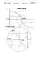
- FIG. 15(a) and FIG. 15(b) both illustrate the home recovery operation performed in the information recording/reproducing apparatus; where FIG. 15(b) is an enlarged view of FIG. 15(a) showing the two speeds used in the home recovery operation;
- FIG. 16 is a block diagram which illustrates the operation of locating the optical head of the information recording/reproducing apparatus.
- FIG. 17 is a flow chart which illustrates the operation of locating the optical head.
- FIG. 4 a first embodiment of an optical card recording/reproducing apparatus 10 performs recording/reproducing data by moving the optical card 1 shown in FIG. 1 in track direction T and as well as moving the optical head 5 in direction CT perpendicular to the track.
- the optical card 1 is detachably loaded into a card holder 6 disposed at a predetermined position of a conveyance belt 1 arranged between two pulleys 12A and 12B.
- the optical card 1 is reciprocated in the direction T (hereinafter called a "track direction") which is in parallel to the linearly-formed track by a holder conveyance motor 15 the rotation of which is controlled by a motor servo circuit 14.
- T the direction
- the light beam to be applied to the optical card 1 scans the same in the track direction T. That is, the above-described holder conveyance motor 15 constitutes a means for relatively moving the light beam in the track direction T.
- a microswitch SW1 When loading of the optical card 1 to a predetermined position of the card holder 6 has been made, for example, a microswitch SW1 is switched on so that a signal denoting the fact that the optical card 1 has been loaded is transmitted to a controller 17.
- the controller 17 rotates the holder conveyance motor 15 via the motor servo circuit 14. As a result, the relative positional location (that is, the presetting action) between the optical card 1 and the optical head 5 is made.
- the controller 17 starts the operation of a timer 17A at a time at which the above-described presetting action will be performed.
- a judgement section 17B judges whether or not presetting OK signal PROK has been supplied within a predetermined time set by the timer 17A so that whether or not the presetting action has been performed normally is judged.
- the controller 17 After the presetting action has been performed normally, data recording/reproducing can be performed. In a case where the presetting action cannot be performed, the controller 17 performs a control in such a manner that it reads retrial data stored in a retrial data recording portion 17C and causes retrial of the presetting action on another track to be performed in accordance with the above-described retrial data.
- the above-described conveyance motor 15 has a rotary encoder 16 fastened thereto for the purpose of detecting the (relative) position (with respect to the optical head 5) of the card holder 6 in the track direction T so that a pulse which is proportion to the angle of the rotation of the motor 15 is transmitted.
- the pulse to be transmitted from the rotary encoder 16 is used to serve as position information in the track direction T in such a manner that one pulse corresponds to a position of 50 ⁇ m of the card holder 6.
- the controller 17 issues a control command to the motor servo circuit 14 so that the optical card 1 is conveyed at a predetermined speed between the two ID portions 3A and 3B.
- the optical head 5 accommodates a laser diode 5A which emits laser beams used to control writing or reading.
- the laser beams are made parallel by a collimator lens 5B.
- the parallel beams are, by a diffraction grating 5C, made into three beams composed of 0-order main beam (sin.) and two sub-beams.
- the three beams are converged by a converging lens (objective lens) 5E via a prism 5D serving as a beam splitter before they are applied to the surface of the optical card 1.
- a converging lens (objective lens) 5E via a prism 5D serving as a beam splitter before they are applied to the surface of the optical card 1.
- three beam spots S are formed on the optical card 1 as shown in FIG. 4.
- the spot is formed at the central portion of the track due to the irradiation of the main beam, while two spots are formed on the two side portions of the main beam spot due to the irradiation of the two sub-beams.
- the spot formed due to the irradiation of the main beam scans data recorded to the surface of the track.
- the photodetector 5F is composed of, for example, four devices consisting of two sectioned devices for receiving the main beam and two devices disposed on the two sides of the two sectioned devices for respectively receiving the sub-beams.
- a photoelectrically converted output from each of the devices, which constitute the photodetector 5F, is received by an addition/subtraction circuit 20 so as to be subjected to addition and subtraction.
- the addition/subtraction circuit 20 adds the outputs transmitted from the two-sectioned devices, which receive the main beam, so that a signal corresponding to data recorded to the surface of the track, that is, reproduction signal RF, is generated. Furthermore, the addition/subtraction circuit 20 subjects the outputs transmitted from the two-sectioned devices to subtraction so that focus error signal FE is generated which denotes the degree of an error from the focused state of the beam spot converged and applied to the optical card 1. Furthermore, the addition/subtraction circuit 20 subjects the two devices, which respectively receive the sub-beams, to a subtraction so that track error signal TE is generated which denotes the positional deviation from the central portion of the track (in the transverse direction of the track).
- the above-described reproduction signal is supplied to a binary & demodulating circuit 18 so as to be converted into a binary number before it is decoded and supplied to the controller 17.
- the binary signal obtained by the binary & demodulating circuit 18 is supplied to an ID mark detection circuit 31 so as to be used to detect an ID mark.
- an ID mark detection signal is supplied to the controller 17 (an ID-mark identifying circuit 17D) and the motor servo circuit 14 (an AND circuit 32 shown in FIG. 5).
- the ID-mark identifying circuit 17D by using the ID mark detection signal, identifies a decode signal which will be supplied from the binary & demodulating circuit 18 in a case where the ID portion is scanned. If the identification is made, the controller 17 (an ID identification circuit 17D of the controller 17) transmits ID confirmation signal IDACK to the motor servo circuit 14 (the AND circuit 32 shown in FIG. 5).
- the focus error signal FE and the track error signal TE are supplied to a focus & track servo circuit 19 so that focusing control signal FC for maintaining the converging lens 5E at a focus state is generated from the focus error signal FE and the track error signal TE. Furthermore, the track servo circuit 19 generates tracking control signal TC for maintaining the tracking state in such a manner that the beam spot formed on the optical card 1 follows up the track.
- control signals FC and TC are respectively supplied to a focusing coil 7a and a tracking coil 7b of a lens driving means 5G so that the converging lens 5C is driven and controlled in the focusing direction (the longitudinal direction of FIG. 4) and the tracking direction (the vertical direction of the sheet on which FIG. 4 is drawn).
- the tracking control signal TC is supplied to the tracking coil 7b via a switch SW2, the switching operation of which is controlled by the controller 17.
- the above-described controller 17 rotates a head moving motor 22 via an optical head drive circuit 21 when moving the optical head 5 to seek an arbitrary track after a presetting operation has been performed so as to move the optical head 5 in direction (hereinafter called a "track transversal direction” or a “track crossing direction”) CT (vertical direction of the drawing sheet on which FIG. 4 is drawn) which intersects the track. Simultaneously with the above-described movement, the beam to be applied to the optical card 1 is moved in the track transversal direction CT. That is, the head motor 22 serves as a means for relatively moving the light beam in the track transversal direction CT.
- the head motor 22 rotates, for example, a spiral thread 8 clockwise or counterclockwise to which the optical head 5 (its housing) is fastened so as to move the optical head 5 in the track transversal direction CT.
- the amount of the movement of the optical head 5 is detected by a rotary encoder 23 fastened to the motor 22 so that an output from the rotary encoder 23 is, via the optical head driving circuit 21, transmitted to the controller 17.
- seeking of a desired track is made in accordance with track address information demodulated by the binary & demodulating circuit 18 to control reading of data.
- the controller 17, similarly to the data reproduction mode, seeks a track, onto which data is desired to be written, before it causes the laser diode 5A via the laser driving circuit 24 to emit high power writing beam to the subject track so that data is written.
- data to be recorded passes through a modulating circuit 25 forming a modulated circuit.
- the modulated circuit is, via the laser driving circuit 24, supplied to the laser diode 5A so that the laser diode 5A emits pulse-formed light at either high or low power in accordance with the binary level of the modulated signal.
- Data to be recorded is, via the controller 17, transmitted to the modulating circuit 25 from a host apparatus (omitted from illustration) such as a computer.
- a command for controlling a driving direction signal (a signal denoting the forward direction or the reverse direction) is supplied from the controller 17 to a ROM 36 which constitutes the motor servo circuit 14, either of two regions of the ROM 36 is selected.
- the ROM 36 is sectioned into two regions composed of a region which stores speed data VD1 for use when the card holder 6 (into which the optical card 1 is loaded) is conveyed in the forward direction and a region which stores speed data VD2 for use when the card holder 6 is conveyed in the reverse direction.
- the address of the ROM 36 corresponds to the positions of the card holder 6 which are arranged apart from each other by a distance of 50 ⁇ m.
- Drive data (aiming speed) for each address is supplied to the conveyance motor 15 via a D/A converter 37 and a power amplifier 38 so that the card holder 6 is conveyed.
- the output denoting the phase-A and the phase-B transmitted from the rotary encoder 16 fastened to the rotary shaft of the motor 15 is supplied to a direction discriminator 39.
- the value of an up/down counter 40 which indicates the position of the card holder 6 with respect to the optical head 5 is updated.
- the difference from an aiming value is calculated by a subtractor 42 via an F/V converter 41 so that speed is controlled in such a manner that the above-described difference is made zero.
- Output data from the ROM 36 is arranged in such a manner that, when the card holder 6 has passed the acceleration region, that is, when the value of the up/down counter 40 exceeds a value which corresponds to the length of the acceleration region, it is converted from acceleration data into a predetermined speed data. When the same has passed through the predetermined speed region and moved into a deceleration region, the output data is converted from the predetermined speed data into deceleration data. When the value of the up/down counter 40 becomes a predetermined value, data denoting the fact that the speed is zero is transmitted to stop the conveyance of the card holder 6.
- FIG. 6 illustrates an example of the speed of the card holder 6 which is controlled in accordance with output data from the ROM 36, wherein Vc denotes the speed which is controlled by the motor servo circuit 14.
- Vc denotes the speed which is controlled by the motor servo circuit 14.
- the ID mark detection circuit 31 detects the ID mark of the ID portions 3A and 3B in response to the binary signal read by the optical head 5 and transmitted from the binary & demodulating circuit 18 so as to transmit a signal denoting the ID mark to the AND circuit 32.
- the above-described detection of the ID mark is performed in such a manner that the binary signal is caused to pass through a shift register 31A and furthermore a comparison is made in a comparator 31B such that whether or not the parallel output from the shift register 31A coincides with pattern data stored in a pattern recording portion 31C for recording the pattern data of the ID portions 3A and 3B.
- a preset data memory 33 is, by the controller 17, caused to store preset data about the position of the ID portions 3A and 3B of the optical card 1.
- Preset data stored in response to a preset data select signal supplied from the controller 17 is supplied to a presetting terminal of the up/down counter 40 so as to be loaded in response to the output from the AND circuit 32. Therefore, the counter 40 increases or decreases the count from preset data when the loading signal is supplied from the AND circuit 32 to the counter 40.
- a predetermined-speed detection circuit 34 decodes the output from the up/down counter 40 and as well as discriminates whether or not, for example, a signal decoded at a predetermined time coincides with a predetermined value to detect the speed (designated by Vc or -Vc of FIG. 6) at which the card holder 6 is conveyed by the motor servo circuit 14, that is, the moment at which the speed is raised to a predetermined speed which is suitable for the recording/reproducing operation.
- the output from the predetermined-speed detection circuit 34 is supplied to the AND circuit 32. Furthermore, ID confirmation signal IDACK transmitted from the controller 17 is supplied to the above-described AND circuit 32. In a case where a signal denoting the result of the logical product is detected, the preset data is set to the up/down counter 40 so that the reliability of the presetting operation is improved.
- the output signal from the above-described AND circuit 32 is supplied to a latch circuit 35 which serves as a preset error discrimination means.
- the latch circuit 35 transmits preset OK signal PROK denoting the fact that the presetting operation has been succeeded to a discriminating portion 17B of the controller 17.
- the controller 17 discriminates in the discriminating portion 17B thereof that the presetting operation has failed if the preset OK signal PROK is not supplied in a predetermined time set by a timer 17A from the time at which the presetting operation has been commenced. In a case where the discrimination has made that the presetting operation has been failed, the controller 17 reads out retry data stored in the retry data recording portion 17C for recording retry data about the presetting operation. In accordance with the retry data, the controller 17 transmits movement command signal MO for moving the optical head 5 to the head motor drive circuit 21. The head motor drive circuit 21 moves the optical head 5 to another track when the movement command signal MO is supplied. Thus, the presetting operation is retried on the track to which the optical head 5 has been moved.
- the latch circuit 35 is arranged in such a manner that is cleared immediately before the presetting operation in response to preset clear signal PRCLR.
- a signal denoting a fact that the switch SW1 has been switched on may be used as the preset clear signal PRCLR.
- FIG. 7 illustrates the track format of the optical card 1 according to the first embodiment.
- the track format for each of the ID portions 3A and 3B according to this embodiment is constituted in such a manner that track address information can be read in both the forward direction and the reverse direction.
- the left-hand ID portion 3A comprises, when viewed from the left portion of FIG. 7, a forward directional ID mark 47A which shows the start point of the ID portion and which acts at the time of the forward directional reading operation, a PLL synchronizing and incoming region 48A which acts at the time of the forward directional reading operation, a synchronous information portion 49A which denotes the starting point of track address information portion and which acts at the time of the forward directional reading operation, a track address information portion 50A, a synchronous information portion 51A which denotes the starting point of track address information and which acts at the time of the reverse directional reading operation, a PLL synchronizing and incoming region 52A which acts at the time of the reverse directional reading operation and an ID mark 53A which denotes the starting point of the ID portion and which acts at the time of the reverse directional reading operation.
- the right-hand ID portion 3B comprises, when viewed from the left portion of FIG. 7, a forward directional ID mark 47B which shows the start point of the ID portion and which acts at the time of the forward directional reading operation, a PLL synchronizing and incoming region 48B which acts at the time of the forward directional reading operation, a synchronous signal 49B which denotes the starting point of track address information portion and which acts at the time of the forward directional reading operation, a track address information portion 50B, a synchronous signal 51B which denotes the starting point of track address information and which acts at the time of the reverse directional reading operation, a PLL synchronizing and incoming region 52B which acts at the time of the reverse directional reading operation and an ID mark 53B which denotes the starting point of the ID portion and which acts at the time of the reverse directional reading operation.
- the track address information portions 50A and 50B serial data modulated from left to right in accordance with a modulation rule is recorded. Therefore, in the forward directional motion, the track address information portions 50A and 50B are ordinarily modulated to reproduce track address information. In the reverse directional motion, the track address information is reproduced in the reverse sequence to the ordinary modulation.
- the controller 17 moves the optical head 5 to a predetermined position such as a home position formed in the optical recording portion 3 when it detects the fact that the optical card 1 has been loaded into the card holder 6. Furthermore, it turns on the focus servo and the track servo, clears the up/down counter 40 and supplies the drive direction signal to the motor servo circuit 14 in order to cause the card holder 6 to be conveyed in the forward direction.
- the motor servo circuit 14 drives the motor in response to the above-described signal to convey the card holder 6.
- the speed of the accelerated card holder 6 has been raised to a speed level which is suitable to perform the recording or the reproducing operation, it is detected by the predetermined-speed detection circuit 34.
- the ID mark 47A is detected by the ID mark detecting circuit 31 after the predetermined-speed position is detected by the predetermined-speed detection circuit 34.
- the controller 17 reads the track address information 50A after the ID mark 47A has been detected and transmits ID confirmation signal IDACK for a predetermined time in which the card holder 6 passes through the ID portion 3A.
- the controller 17 is able to recognize the ID portion 3A in accordance with the track address information 50A (since information denoting the ID portion 3A is included). Therefore, the controller 17 transmits a preset data select signal so as to make the output from the preset data memory 33 to be a value which corresponds to the position of the ID mark 53A.
- This embodiment may be arranged in such a manner that, for example, ID confirmation signal IDACK is, as designated by a dashed line of FIG. 5, also used as the preset data select signal.
- the output from the AND circuit 32 becomes active and the value of the preset memory 33 is set to the up/down counter 40.
- the position of the optical card 1 with respect to the optical head 5 can be detected. Therefore, an error which occurs at the time of the operation of loading the optical card 1 with respect to the card holder 6 can be corrected. That is, the position of the optical card 1 with respect to the card holder 6 can be corrected.
- the AND circuit 32 has become active, the latch circuit 35 latches "H" data to transmit it as preset OK signal PROK to the discriminating portion 17B of the controller 17 so that a discrimination is made that the presetting operation has been completed normally.
- the ID portion 3A cannot accurately be demodulated. Therefore, the ID confirmation signal IDACK cannot be transmitted from the ID portion 3A and, therefore, the value of the preset data memory 33 is not set to the up/down counter 40.
- the card holder 6 is brought to a predetermined-speed state in the data portion 4 and the fact that it has been brought to the predetermined-speed position is detected by the predetermined-speed detection circuit 34. Then, the controller 17 detects the ID mark 47B of the right-hand ID portion 3B before it reads the track address information 50B so that it transmits the ID confirmation signal for a predetermined time.
- the controller 17 is able to recognize the fact that the subject portion is the ID portion 3B from the track address information 50B. Therefore, the controller 17 transmits the preset data select signal so as to make the output from the preset data memory 33 to be a value which corresponds to the position of the ID mark 53B.
- the output from the AND circuit 32 is brought into the active state. Therefore, the value of the preset data memory 33 is set to the up/down counter 40. As a result, the error which occurs at the time of the loading operation of the optical card 1 with respect to the card holder 6 can be corrected. Since preset OK signal PROK is transmitted, the sequence can be shifted to the next operation.
- preset OK signal PROK is not transmitted.
- the controller 17 rotates the moving motor 22 via the optical head driving circuit 21 so that the optical head is moved by, for example, 5 mm in the track transversal direction CT which intersects the track. Then, the controller 17 again moves the card holder 6 to repeat the presetting operation. Since the defect present on the optical card 1 is usually limited to about 1 mm, the optical head 5 is removed from the track at which the retrial operation has failed. Therefore, the probability that the presetting operation will succeed is increased.
- the structure according to Japanese Patent Laid-Open No. 2-154364 is able to work as desired in the above-described cases (a) and (b).
- retrying is made in such a manner that the movement to another track is performed while deviating from the portion in the vicinity of the track in which the presetting operation has been failed. Therefore, the probability that the presetting operation will succeed is increased.
- FIG. 8 illustrates the contents of the presetting operation according to this embodiment.
- step S1 When the optical card 1 is inserted into a predetermined position of the card holder 6 in step S1, the timer 17A is started as shown in step S2. Furthermore, the focus servo is turned on in step S3. Then, in step S4, the track servo is turned on so that a state is realized in which the adjacent track is followed up. Then, in step S5, the card holder 6 is driven (conveyed) so that the presetting operation is performed in step S6 in the above-described state of driving. Then, a discrimination is (in step S7) made whether or not the presetting operation has succeeded or failed such that preset OK signal PROK has been transmitted in a predetermined time set by the timer 17A. If the same has succeeded, the operational sequence proceeds to the next operation (for example, the recording or the reproducing operation).
- the next operation for example, the recording or the reproducing operation.
- step S8 a discrimination that the subject retrial is the N-th time (N can be predetermined) is made (step S8). If it is not the N-th time, a process in which the track servo is turned off is performed in step S9. Then, the flow proceeds to step S10 in which the optical head 5 is moved in the track transversal direction CT which intersects the track.
- step S4 in which the track servo is turned on to realize a state in which the track adjacent to the position, to which optical head 5 has been moved, is followed up before next step S5 is repeated.
- step S8 If the retrial is the N-th time in step S8, it can be considered that presetting has not failed due to the defects on the surface of the optical card 1 but the same has failed due to, for example, a breakdown of the apparatus. Therefore, a discrimination is made that a preset error has occurred and a predetermined process arranged to be performed if an error has occurred.
- the position correction is again performed at another track by moving the optical head 5. Therefore, the probability that the position is again corrected on another track in which dust or a defect is present can be improved. Therefore, the probability that the position correction succeeds can be improved.
- the optical card which cannot be subjected to recording or reproducing according to the conventional technology can be subjected to the same.
- the optical card from which data cannot be reproduced according to the conventional technology can be subjected to the reproducing process. Therefore, the possibility of reproducing precious data can be improved.
- FIG. 9 illustrates an essential portion of a modification to the first embodiment of the present invention.
- This modification is arranged in such a manner that, if the preset operation fails, the controller 17 (its discriminating portion 17B) switches over the switch SW2 from contact a to b in place of driving the head motor 22 so as to supply the track transversal signal transmitted from a track transversal signal generating circuit 61 to a tracking coil 7b.
- the converging lens 5E is moved in the track transversal direction CT so that the beam is moved to another track.
- step S10 shown in FIG. 8 is modified in such a manner that the drive signal is supplied to the tracking coil 7b of the lens driving means 5G in place of the process in which the optical head 5 is moved.
- the beam spot is moved to a track which is different from the track to which the presetting operation has failed so as to the presetting operation is again performed on the above-described track.
- FIG. 10 shows the retrial of the presetting operation.
- Another structure may be employed which is a combination of proper factors arranged such that, if the preset operation has failed, the lens driving means 5G is first driven and a larger movement is made by the optical head to perform the retrial.
- FIG. 8 Although the structure shown in FIG. 8 is arranged in such a manner that the presetting operation is again performed by moving the optical head 5 in a case where the presetting operation has failed (except for the case in which the N-th retrial), another structure may be employed which is arranged in such a manner that, if the presetting operation has failed in spite of performing plural times of retrial operations while remaining the position of the optical head 5, the optical head 5 or the like is moved to perform the retrial on another track.
- FIG. 11 illustrates a portion of a second embodiment of the present invention.
- the card holder 6 into which the optical card 1 is loaded is moved in the track transversal direction CT to convey the optical head 5 in the track direction T.
- the two end portions of a screw 71 secured to the card holder 6 are, by the thread, received by thread holes formed in support columns 73 stood erect on the base 72.
- the rotational shaft of a motor 74 is secured to an end portion of the screw 71.
- a rotary encoder 75 is fastened to the rotational shaft of the motor 74.
- the above-described screw 71 is made to project in a direction perpendicular to the track of the optical card 1. As a result, the card holder 6 is moved in the track transversal direction CT by the motor 74.
- the two end portions of a screw 77 secured to the optical head 5 are, by the thread, received by thread holes of supporting columns 78 stood erect on a base 72.
- the screw 77 is, by the thread, engaged with a gear 80 fastened to the rotational shaft of a motor 79.
- a rotary encoder 81 is fastened to the rotational shaft of the above-described motor 79.
- the motor 79 is secured to a supporting column stood erect on the base 72.
- the above-described screw 77 is made to project in the track direction T running parallel to the track of the optical card 1. As a result, the optical head 5 is moved in the track direction T by the motor 79.
- the rotation of the above-described motor 74 is controlled by the motor driving circuit 21 shown in FIG. 4, while that of the motor 79 is controlled by the motor servo circuit 14.
- the first embodiment is arranged in such a manner that the card holder 6 is conveyed in the track direction T and the optical head 5 is moved in the track transversal direction CT
- the second embodiment is arranged in such a simple manner that the card holder 6 is moved in the track transversal direction CT and the optical head 5 is conveyed in the track direction T.
- the other structures are the same as those according to the first embodiment.
- the operation and the effect obtainable from to this embodiment are the same as those obtainable from the first embodiment.
- the optical head 5 or the like is moved if the preset operation fails to move at least the light beam in the track transversal direction CT so as to perform the retrial on another track. Therefore, even if an error has occurred at the time of the presetting operation due to a defect on the surface of the optical card 1, the probability of recovery by means of the retrial can be improved to perform the ensuing normal recording operation.
- the conventional optical card apparatus is arranged in such a manner that the home position recovery operation is performed at a predetermined and relatively slow speed. Therefore, it takes too long time for the home position recovery operation to be completed in a case where the amount of the movement of the head carriage is great at the time of the home position recovery operation. That is, the conventional optical apparatus is arranged in such a manner that the home position recovery operation is always performed by the same process.
- the head carriage is moved toward the home position at a predetermined speed in a case where tracking has been disrupted due to dust or a flaw of the optical card and thereby the optical head has run away or in a case where the positional relationship between the optical head and the home position is substantially known at the time of the commencement of the home recovery operation in the recording/reproducing mode or the card insertion/discharge mode. Therefore, there arises a problem in that a too long time takes to complete the home recovery operation in a case where the head carriage is positioned away from the home position.
- an optical card 130 serving as a recording medium has a track 132 extending in the longitudinal direction of the card, the track 132 having a plurality of recording regions 133 formed in the widthwise direction (in the minor side direction) of the optical card 130.
- the recording region 133 has, on the two end portions of the minor side thereof, ID portions 134a and 134b to which information about the address which corresponds to each track is recorded so that the ID portions 134a and 134b can be read from in the opposite directions.
- a data portion 135 is formed between the above-described ID Portions 134a and 134b.
- the ID portion 134a is read to recognize address information corresponding to the track. Furthermore, in a case where the optical card 130 is, with respect to the head carriage, moving from right to left in FIG. 12 along the track, the ID portion 134b is read to recognize address information corresponding to the track.
- the above-described ID portion 134a and 134b are formed inside away from the end portion of the optical card 130 by a predetermined distance (for example, about 4 mm) in order to prevent the influence of the flaw or contamination in the end portion of the card 130 and as well as to satisfactorily stable the relative speed between the optical card 130 and the optical head in the track direction.
- the ID portions 134a and 134b are previously formatted when the optical card 130 is manufactured.
- the optical card apparatus 1 serving as the information recording and reproducing apparatus has an actuator 102 for causing recording/reproducing beam to be applied to the optical card 130.
- the actuator 102 is structured in such a manner that an optical spot is applied to the surface of the optical card 130 via an optical system composed of a light source, an objective lens, and the like (omitted from illustration).
- the actuator 102 is fastened to a head carriage 103.
- the actuator 102 is driven by a voice coil motor (VCM) 104 mounted on the head carriage 103 in such a manner that it is able to be moved in a direction substantially perpendicular to the track 132 of the optical card 130.
- VCM voice coil motor
- a linear scale 106 is fastened to the head carriage 103, the linear scale 106 is combined with a scale detector 108 which serves as a home position detection means fastened to a frame 107 to which the head carriage 103 is movably fastened.
- the linear scale 106 is able to detect the home position (H) serving as the reference position and to detect the position change.
- the linear scale 106 comprises a home position detection area 106A having a bright and dark pattern showing the home position and a position detection slit area 106B having a plurality of slits 109 for detecting the position change in the direction substantially perpendicular to the track 132 of the optical card 130.
- the light and bright pattern of the linear scale 106 is arranged in such a manner that it is changed at, for example, the central portion of the major side of the linear scale 106, the change position of the bright and dark pattern being made to be the home position.
- the above-described home position is arranged in such a manner that it corresponds to, for example, the central portion of the minor side of the optical card 132.
- the scale detector 108 is arranged to transmit a pattern signal, which corresponds to the bright and dark state of the pattern of the linear scale 106 to a sequence control circuit 110 and a home speed processing circuit 111.
- the sequence control circuit 110 detects the change point of the bright and dark pattern to recognize the fact that the head carriage 3 is positioned at the home position.
- the position change is detected in accordance with the known moire fringe principle by means of the slits 109 of the linear scale 106 and sub-slits (omitted from illustration) formed on the scale detector 108. That is, the scale detector 108 detects the position change in the direction substantially perpendicular to the track 132 of the optical card 130 to transmit the position displacement signal to a speed detection circuit 112, a first counter 113 and a second counter 114.
- the home speed detection circuit 111 detects the right side or the left side (designated by symbol a or b of FIG. 14) on which the actuator 102 is positioned with respect to the home position in response to the pattern signal transmitted from the scale detector 108. The home speed detection circuit 111 then transmits an aiming speed signal for moving the head carriage 103 to the home position to the z-side input of a speed changing circuit 115.
- the speed detection circuit 112 detects the present moving speed of the head carriage 104 in accordance with the position displacement signal transmitted from the scale detector 108 so as to supply it to a speed calculating circuit 116.
- the first counter 113 receives a resetting signal supplied from the sequence control circuit 110 at the time of the power supply. Furthermore, it detects the present position change of the head carriage 103 while making the position to which the above-described reset signal is supplied to be the reference position so as to transmit the result of the detection to the sequence control circuit 110 and a speed table 117 serving as a speed pattern generating means.
- the aiming position which is set by the sequence control circuit 110 and to which the head carriage 103 is moved at the time of the seeking operation, is set to an aiming position setting circuit 118 to transmit a signal denoting the set position to the speed table 117.
- the speed table 117 generates a signal denoting the difference in the present position transmitted from the first counter 113 and the aiming position transmitted from the aiming position setting circuit 118, that is, an aiming speed signal determined in accordance with the distance to the aiming position so as to transmit it to y-input terminal of the above-described speed changing circuit 115.
- the speed changing circuit 115 selects the aiming speed signal to the home position transmitted to the home speed processing circuit 111 or the aiming speed signal transmitted from the speed table 117 so as to transmit the selected signal to the speed calculating circuit 116 via an x-output terminal.
- the speed calculating circuit 116 subtracts the present speed signal transmitted from the speed detection circuit 112 from the aiming speed signal transmitted from the x-output terminal of the speed changing circuit 116 so as to transmit it as a speed error signal to a y-input terminal of a speed/position switching circuit 119.
- the second counter 114 counts the position displacement signal transmitted from the head carriage 103 from the position to which the reset signal is supplied from the sequence control circuit 110 so as to detect the position displacement of the head carriage to transmits the result to a phase compensating and calculating circuit 120.
- the sequence control circuit 110 supplies a reset signal to the second counter 114 when the head carriage 103 has reached the aiming position at which the head carriage 103 must be stopped.
- the phase compensating calculating circuit 120 performs calculations to make the head carriage 103 to be positioned at the aiming position in accordance with the output denoting the difference between the aiming position and the present position.
- An output signal denoting the result of the calculations is supplied to a z-input terminal of the speed/position switch circuit 119.
- the speed/position switch circuit 119 selects the speed error signal transmitted from the speed calculating circuit 116 or the position displacement signal transmitted from the phase compensating and calculating circuit 120 in accordance with the instruction issued from the sequence control circuit 110.
- the selected input signal is transmitted to a digital/analog (D/A) converter 121 via the x-output terminal.
- D/A digital/analog
- the D/A converter 121 converts a digital output signal transmitted from the speed/position switching circuit 119 into an analog signal so as to transmit it to the y-input terminal of the position control switching circuit 122.
- a lens position detection circuit 123 detects the position of an object lens included in the actuator 10 so as to transmit a signal for controlling the position of the head carriage 3 to the z-input terminal of the position control switching circuit 122 so that the displacement of the object lens can be minimized.
- the position control switch circuit 122 selects a lens position signal transmitted from the lens position detection circuit 123 or a signal transmitted from the D/A converter 121 so as to transmit the selected signal to a power amplifier 124 via the x-output terminal.
- the power amplifier 124 drives a VCM 104 with an electric current which is in proportion to the signal transmitted from the D/A converter 121 so as to move the head carriage 103 at a predetermined speed or position the same at a predetermined position.
- the optical card apparatus 101 has a photodetector (omitted from illustration) for converting light reflected by the optical card 130 into an electric signal.
- the above-described photodetector transmits an information reproduction signal to a demodulating circuit (omitted from illustration).
- the optical card apparatus 101 performs the tracking servo control and the focusing servo control by using the output signal transmitted from the above-described photodetector.
- FIG. 15(a) and FIG. 15(b) the operation to be performed when the optical card apparatus 101 according to the present invention is moved to the home position will now be described.
- the home position recovery operation is performed in each of the above-described operations (1) to (3).
- the home recovery operation will now be described sequentially. (1) First, the home recovery operation to be performed at the time of the home supply will now be described.
- the scale detector 108 shown in FIG. 14 detects a fact that the head carriage 103 is positioned on the portion a or b of the home position.
- the level of the pattern signal transmitted from the scale detector is made to be a high level.
- the level of the pattern signal transmitted from the scale detector 108 is made to be a low level so that the side of the home position on which the head carriage 103 is positioned is detected.
- the home speed processing circuit 111 transmits aiming speed "+V2" during a period in which the level of the pattern signal is high, while the same transmits aiming speed "-V2" during the period in which the level is low.
- the sequence control circuit 110 instructs the speed switching circuit 115 to select the output from the home speed processing circuit 111 so as to transmit the selected output to the speed calculating circuit 116.
- the speed calculating circuit 116 has received the present movement speed of the head carriage 103 from the speed detection circuit 112. Therefore, a signal denoting the difference between the two speed levels is transmitted to the VCM 104 via the D/A converter 121, the position control switching circuit 122 and the power amplifier 124.
- the head carriage 103 is, as designated by a dashed line of FIG. 15(a) in the range of the portion a of FIG. 14, moved at predetermined speed "+V2" in the direction toward the home position, while the same is moved at predetermined speed "-V2" in the range of the portion b of FIG. 13, in the direction toward the home position.
- the sequence control circuit 110 supervises the pattern signal transmitted from the scale detector 108 to recognize the position, at which the pattern signal has been changed from the high level to the low level, as the home position so that it transmits the resetting signal to the second counter 114. Furthermore, the sequence control circuit 110 issues an instruction to select the z-input side of the speed/position switching circuit 119.
- the second counter 114 commences counting when it receives the resetting signal supplied from the sequence control circuit 110.
- the phase compensating and calculating circuit 120 supplies its output to the VCM 104 via the D/A converter 121, the position control switching circuit 122 and the power amplifier 124. That is, the second counter 114 is reset to zero at the home position. At this position (the home position), the head carriage 103 is located. (2) Then, the description will be made about the movement of the light spot to the aiming track and the home recovery operation at the time of the runaway of the head carriage during the R/W operation.
- the optical card apparatus 101 is arranged in such a manner that the movement of the light spot in the tracking direction is made at the two end portions of the optical card 130 and the R/W operation is performed while moving the optical card 130 in the tracking direction.
- the sequence control circuit 110 sets data to the aiming setting circuit 118, the data corresponding to the position of a desired track.
- the first counter 113 is reset at the home position at the time of the power supply as described in (1). If the position of the head carriage 103 is not changed afterwards, the first counter 113 is set to zero (the home position).
- the speed table 117 transmits the speed which corresponds to the distance from the present position (the home position) to the aiming position as the aiming speed.
- the speed pattern to be transmitted from the speed table 117 is, as shown in FIG. 15(b), arranged to be high speed in a case where the distance to the aiming position is long and to be low speed in proportion to the distance.
- Both of the speed switching circuit 115 and the speed/position switching circuit 119 are switched to the y-input terminals.
- the head carriage 103 commences the movement to the aiming track.
- the speed of the head carriage 103 is decelerated in accordance with the above-described speed pattern in proportion to the distance from the aiming position until it is set to predetermined speed "V1" just before the aiming position.
- the second counter 114 is reset and the speed/position switching circuit 119 is switched to the z-terminal so that the head carriage 103 is brought to the locating operation.
- the light spot is brought into the tracking operation state in which it follows up the aiming track.
- the optical card 130 is driven in the tracking direction and the R/W operation is, if necessary, performed.
- the optical spot following up the displacement of the track in the tracking direction is performed in such a manner that the objective lens included in the actuator 102 is moved.
- the position control switching circuit 122 is switched over to the z-input side so that the position of the head carriage 103 is controlled such that the displacement of the lens during the tracking operation is minimized.
- the first counter 113 remains supervising the present position displacement signals transmitted from the scale detector 108 during the R/W operation or in the case of the runaway. Furthermore, the sequence control circuit 110 remains supervising the output from the first counter 113. Therefore, it is able to recognize the runaway state from the change in the position displacement signal so that it, as described later, returns the head carriage 103 to the home position and it again moves to the aiming track if the runaway takes place.
- the light spot is moved on the optical card 130 to an end portion of the optical card 130 which is different from the end portion at the previous operation.
- the reason for this lies in that, if the R/W operation is retried again, the influence of dust or a flaw is changed and thereby the tracking operation is not necessarily made unstable. As a result, the R/W operation can sometimes be performed normally.
- the home recovery operation to be performed at the time of runaway is performed as follows in a manner different from the operation to be performed at the time of the power supply.
- the sequence control circuit 110 issues an instruction to switch over all of the speed changing circuit 115, the speed/position switching circuit 119 and the position control switching circuit 122 to the y-input terminal. Therefore, the head carriage 103 is moved to the home position in accordance with the speed pattern shown in the speed table 117.
- Continuous lines of FIGS. 15(a) and 15(b) designate the aiming speed at the time of the home recovery operation to be performed when the runaway takes place.
- FIGS. 15(b) is an enlarged view of a portion of FIG. 15(a).
- the speed, at which the head carriage 103 is moved toward the home position is made to be higher than "+V2".
- the speed is changed to "+V1" via "+V2" in proportion to the distance from the home position.
- the sequence control circuit 110 switches over the speed/position switching circuit 119 to the phase compensating and calculating circuit 120 at the switch position of the pattern signal transmitted from the scale detector 108 so that locating to the home position is made.
- the head carriage 103 In a case of the movement from the range of the portion b and as well as the distance of the movement is long, the head carriage 103 is brought to the home position at a speed higher than "-V2". Furthermore, the speed is made to be "-V1" via "-V2" in proportion to the distance from the home position before it is located to the home position. In a case where the distance of the movement to the home position is short, the head carriage 103 commences its movement at a speed of, for example, " ⁇ V2" in proportion to the distance. Then, the carriage 103 is brought to the home position at a speed of, for example, " ⁇ V1" so as to be located.
- the movement speed of the head carriage 103 exceeds "i V2" and the same is decelerated in proportion to the distance to the home position. Therefore, the movement time can be reduced in comparison to that required at the time of the power supply shown in (1) and the home recovery operation. Since the speed at which the head carriage 103 is brought to the home position is arranged to be less than that arranged at the time of the power supply, the time (setting time) taken to the moment at which the position of the head carriage 103 is stabled in the locating operation to the home position can be shortened.
- the optical card apparatus according to the present invention is arranged in such a manner that the home recovery operation is performed at the time of the discharge of the card and the next insertion of the card. Since the positional relationship between the head carriage 103 and the home position has been previously known in the above-described case, the home recovery operation is performed similarly to the operation to be performed when runaway takes place as shown in (2). However, after the movement to the home position has been made, the sequence control circuit 110 resets the first counter 113 in a state where the locating operation has been stabled. The reason for this lies in that the influence of an erroneous count made by the first counter 113 due to generation of noise or the like on the next process must be prevented.
- the movement of the head carriage 103 is controlled in accordance with the speed pattern for use in the seeking operation so as to be moved to a position adjacent to the home position. Furthermore, the pattern signal transmitted from the scale detector 108 is supervised to confirm the home position. As a result, locating can be performed. Therefore, the time which taken to complete the setting can be shortened due to the high speed movement to the home position and the realized low speed movement to the home position. As a result, the home recovery time can be reduced and thereby the processing speed in the apparatus can be reduced.
- Reference numeral 201 represents an optical card serving as the recording medium which has a multiplicity of straight and parallel information tracks formed in a predetermined region.
- An optical card driving apparatus 202 is capable of driving the optical card 201 in the direction of the track, the optical card driving apparatus 202 being controlled by an optical card control device 203.
- An optical head 204 emits beam spots to the surface of the track formed on the optical card 201 to record/reproduce data.
- a read signal processing apparatus 205 demodulates and reproduces information written in the portion on the track in response to a signal read by the optical head 204.
- the optical head 204 is mounted on a carriage 206 so as to be driven in a direction perpendicular to the track formed on the optical card 201.
- Reference numeral 207 represents a carriage driving device for driving the carriage 206.
- Reference numeral 208 represents a carriage control device for controlling the carriage driving device 207.
- a home scale 209 acts to detect the home position formed on the optical card 201, the home scale 209 being secured to the carriage 206.
- a home scale detector 210 transmits a signal which is made to be "0" or "1” in accordance with the status of the home scale 209.
- a signal transmitted from the home scale detector 210 that is, an HS signal, is supplied to the carriage control device 208 and a scale signal supervising device 213 to be described later.
- the apparatus according to the present invention is arranged in such a manner that the linear scale 211 is secured to the carriage 206. Furthermore, the linear scale 211 has black portions (portions which do not reflect light) and non-black portions (portions which reflect light) which are alternately formed at intervals which correspond to the track pitch width of the optical card 201. The above-described interval is made to be about 12 microns according to this embodiment.
- the linear scale detector 212 transmits a signal (hereinafter called an "LS signal") which is made to be "0" or "1" in accordance with the status of the linear scale 211.
- the number of pulses of the LS signal corresponds to the number of the tracks.
- the scale signal supervising device 213 supervises the LS and HS signals and comprises a linear scale counter 214 for counting the number of the pulses of the LS signal and a linear scale counter value storage device 215 for storing the value of the linear scale counter 214.
- the scale signal supervising device 213 is connected to the carriage control device 108.
- a system controller 216 controls the overall operation of the optical card apparatus and the same is connected to the optical card control device 203, the read signal processing device 205, the carriage control device 208 and the scale signal supervising device 213.
- the linear scale counter 214 connected to the scale signal supervising device 213 is initialized to a value of zero by the system controller 216 (step S201).
- a discrimination is made whether or not the subject operation is the first locating operation (step S202).
- the number of retrials is set to a memory to which the number of retrials of reading the ID portions at the time of the locating operation is set, for example, a counter (step S203).
- the range of movement of the carriage 206 is set to the scale signal supervising device 213.
- the carriage movement range according to this embodiment is arranged to a range on the surface of the optical card 201 to which data can be recorded.
- the carriage control device 208 drives the carriage 206 in a direction in which the HS signal becomes "0", that is, in the forward direction until the edge of the HS signal is detected (step S206).
- the carriage drive device 207 drives the carriage 206 in a direction in which the HS signal becomes "0", that is, in the forward direction until the edge of the HS signal is detected (step S206).
- the HS signal is "0" (step S205)
- the same is driven in a direction in which the HS signal becomes "1", that is, in the reverse direction until the edge of the HS signal is detected (step S207).
- a discrimination is made whether or not the subject operation is the first locating operation (step S209). If the subject operation is the first locating operation, the carriage control device controls the carriage driving device 207 to stop the carriage 206 (step S210). Then, the optical card 201 is driven in the direction of the track by the optical card driving device 202 to read the ID portion (step S211). The signal read by the optical head 204 is demodulated and reproduced by the read signal processing device 205 which reproduces information.
- step S212 Information reproduced is supplied to the system controller 216 so as to be subjected to a discrimination whether or not the same has been correctly reproduced by a discrimination circuit included in the system controller 216 (step S212). Then, the operation to be performed if the same has been reproduced correctly, that is, information about the track could be obtained from the read ID portion will now be described.
- the home position of the optical head 204 is set only by the home scale 209. After the home position has been detected, the carriage 206 is not moved. That is, since the overall amount of movement of the carriage 206 is zero, the linear scale counter 214 displays the initial value, that is, "0" which is then stored in the linear scale counter value storage device 215 (step S213). Then, the positional relationship between the optical card 201 and the optical head 204 is set by using the above-described track information (step S214). Thus, locating of the optical head is completed.
- the ID portion is again read in a range set to the above-described retry number counter for counting the retrials of the ID portion at the time of locating the optical head (steps S212 and S215). If the ID portion cannot be reproduced in the above-described reading operation, a discrimination is made whether or not the subject region is included in a predetermined carriage movable range (step S216). If the subject region is included in the above-described range, the carriage 106 is moved in the forward direction (S217).
- the linear scale counter 214 mounted on the scale signal supervising device 213 is made active and the carriage 206 is driven by the carriage driving device 207.
- the linear scale counter 214 counts the number of pulses of the LS signal generated by the linear scale detector 212 in accordance with the movement of the carriage 206.
- the number of the pulse of the LS signal counted corresponds to the number of tracks traversed by the optical head 204 from the track at which it is positioned before the movement to the track to which the same is moved. Therefore, by supervising the value of the linear scale counter 214, the amount of movement of the carriage 206 can be determined.
- the scale signal supervising device 213 supervises the linear scale counter 214 to move the carriage 206 by a predetermined quantity.
- the above-described predetermined quantity is previously set to a value within a range in which it does not come across dust or contamination present on the track.
- the carriage 206 is stopped to drive the optical card 201 so as to read the ID portion on the track to which the optical head 204 has been moved (step S211).
- the above-described operation is repeated until the ID portion can be correctly read in the previously set carriage movement range (steps S212 and 215 to 217).
- the value of the linear scale counter 214 at this time that is, the total quantity of the movement of the carriage 206 from the home position set by the home scale 209, is stored in the linear scale counter value storage device 215 (step S213). Furthermore, the positional relationship between the optical card and the optical head is set by using read track information (step S214). Thus, locating of the optical head 204 is completed. If the ID portion could not be reproduced in the set carriage movable range (step S216), a discrimination is made that an error of reading the ID portion has occurred and the occurrence of the abnormality is notified to the system controller 216 (step S218). The system controller 216, which receives the notification of the abnormality, performs a process of discharging the card or the like.
- the linear scale counter 214 is again initialized by the system controller 216 (step S201). Since the number of the retrials of reading the ID portion and the carriage movable range have been previously set, the above-described operations are not performed.
- the status of the home scale 209 is, similarly to the first locating operation, examined by the carriage control device 208 in response to the HS signal transmitted from the home scale detector 210.
- the carriage 206 is driven in a direction in which the edge of the HS signal is obtained until the same is detected (steps S205 to S208).
- the linear scale counter 214 is simultaneously brought into the active state. Then, a discrimination is made that the subject operation is the second or the ensuing operation of locating the optical head 204 (step S209).
- the carriage 206 is moved such that the value of the linear scale counter 214 approximates the total amount of the optical head 204 from the home position at the first operation of locating the optical head, that is, the value stored in the linear scale counter value storage device 215 (step S219).
- the value of the linear scale counter 214 is changed during the movement, the above-described values is subjected to a comparison with the above-described total quantity of the movement by a comparator included in the scale signal supervising device 213. Then, the carriage 206 is stopped at a position at which the above-described values coincide with each other.
- the track placed at the above-described position to which the carriage 206 has been moved is the track from which the ID Portion has been correctly reproduced at the time of the first operation of locating the optical head. Then, the optical card 201 is moved to read the ID portion of this track (step S220) to set the positional relationship between the optical card 201 and the optical head 204 by using information about the above-described track (step S214). Thus, the second or the ensuing operation of locating the optical head is completed.
- the optical head in a case where the optical head cannot be moved to its home position set by the home scale 209, the optical head is moved by a predetermined quantity to change the home position for the optical head in order to perform locating of the optical head. Therefore, even if dust, contamination or a flaw is present on a specific track of the optical card, the optical head can be stably located. Furthermore, the position which has been subjected to the first locating operation is stored. Therefore, it is necessary for the operation of locating the optical head to be simply performed in such a manner that the optical head is located at the position which is moved by a previously stored quantity from the position determined by the home scale 209. Therefore, the operation of locating the optical head can be completed in a short time and thereby a reliable optical card apparatus can be provided.
- the above-described embodiment is arranged in such a manner that the carriage is moved in the forward direction at the time of the change of the home position, a similar effect can, of course, be obtained from an arrangement in which the same is moved in the reverse direction.
- the forward directional movement and the reverse directional movement may be combined with each other.
- a structure may, of course, be employed in which the operation of locating the optical head after changing the home position for the optical head is performed by further changing the home position within the carriage movable range if locating of the optical head becomes impossible at the changed home position for the optical head during the operation of the optical card apparatus.
- a problem can occur in that the overall optical recording medium cannot be used due to a failure of a specific track on the optical recording medium can be prevented. Therefore, the positional relationship between the optical head and the optical recording medium can stably and at high speed set. Therefore, a reliable information recording/reproducing apparatus can be provided.
Landscapes
- Physics & Mathematics (AREA)
- General Physics & Mathematics (AREA)
- Engineering & Computer Science (AREA)
- Theoretical Computer Science (AREA)
- Optical Recording Or Reproduction (AREA)
- Moving Of The Head For Recording And Reproducing By Optical Means (AREA)
- Moving Of The Head To Find And Align With The Track (AREA)
Applications Claiming Priority (2)
| Application Number | Priority Date | Filing Date | Title |
|---|---|---|---|
| JP3-9170 | 1991-01-29 | ||
| JP3009170A JP2888495B2 (ja) | 1991-01-29 | 1991-01-29 | 光カード装置 |
Publications (1)
| Publication Number | Publication Date |
|---|---|
| US5298730A true US5298730A (en) | 1994-03-29 |
Family
ID=11713118
Family Applications (1)
| Application Number | Title | Priority Date | Filing Date |
|---|---|---|---|
| US07/824,285 Expired - Fee Related US5298730A (en) | 1991-01-29 | 1992-01-23 | Optical card apparatus in which retrial of locating operation of optical card is retried on another track at the time of loading the same |
Country Status (2)
| Country | Link |
|---|---|
| US (1) | US5298730A (ja) |
| JP (1) | JP2888495B2 (ja) |
Cited By (5)
| Publication number | Priority date | Publication date | Assignee | Title |
|---|---|---|---|---|
| US5380996A (en) * | 1992-07-10 | 1995-01-10 | Olympus Optical Co., Ltd. | Optical card recording/regenerating method and apparatus for driving optical card with respect to optical head so as to increase or decrease relative speed in at least one of ID divisions of optical card |
| US5739519A (en) * | 1993-11-05 | 1998-04-14 | Canon Kabushiki Kaisha | Information recording method |
| WO2001029835A1 (en) * | 1999-10-15 | 2001-04-26 | Trid Store Ip, Llc | Apparatus for information retrieval from a multilayer fluorescent optical clear card |
| US20040004123A1 (en) * | 1999-05-24 | 2004-01-08 | Sadler John W. | Apparatus and method for scanning a surface |
| US20080159107A1 (en) * | 2002-09-02 | 2008-07-03 | Heung-Chan Seung | Copying apparatus for copying a recoding medium, a method thereof and a computer program thereof |
Families Citing this family (1)
| Publication number | Priority date | Publication date | Assignee | Title |
|---|---|---|---|---|
| JP2010040148A (ja) * | 2008-08-08 | 2010-02-18 | Hitachi Ltd | 情報記録媒体および情報記録再生装置 |
Citations (6)
| Publication number | Priority date | Publication date | Assignee | Title |
|---|---|---|---|---|
| JPH02154364A (ja) * | 1988-12-06 | 1990-06-13 | Olympus Optical Co Ltd | 光カード装置 |
| US4950876A (en) * | 1987-07-31 | 1990-08-21 | Olympus Optical Co., Ltd. | Optical card recording/reproducing apparatus with compensation for displacement deviation between data area of optical card and laser beam |
| US4982391A (en) * | 1987-02-20 | 1991-01-01 | Canon Kabushiki Kaisha | Method and apparatus for accessing a desired track of a recording medium during a stopped state of recording or reproduction |
| US5008552A (en) * | 1987-02-12 | 1991-04-16 | Dai Nippon Insatsu Kabushiki Kaisha | Data recording and reproducing apparatus for an optical card |
| US5083301A (en) * | 1988-05-13 | 1992-01-21 | Sharp Kabushiki Kaisha | Optical card recording and reproducing device |
| US5105072A (en) * | 1991-03-06 | 1992-04-14 | Olympus Optical Co., Ltd. | Optical information recording/reproducing apparatus having stopping position deviation and correction circuitry relative to movement in the track direction |
-
1991
- 1991-01-29 JP JP3009170A patent/JP2888495B2/ja not_active Expired - Lifetime
-
1992
- 1992-01-23 US US07/824,285 patent/US5298730A/en not_active Expired - Fee Related
Patent Citations (6)
| Publication number | Priority date | Publication date | Assignee | Title |
|---|---|---|---|---|
| US5008552A (en) * | 1987-02-12 | 1991-04-16 | Dai Nippon Insatsu Kabushiki Kaisha | Data recording and reproducing apparatus for an optical card |
| US4982391A (en) * | 1987-02-20 | 1991-01-01 | Canon Kabushiki Kaisha | Method and apparatus for accessing a desired track of a recording medium during a stopped state of recording or reproduction |
| US4950876A (en) * | 1987-07-31 | 1990-08-21 | Olympus Optical Co., Ltd. | Optical card recording/reproducing apparatus with compensation for displacement deviation between data area of optical card and laser beam |
| US5083301A (en) * | 1988-05-13 | 1992-01-21 | Sharp Kabushiki Kaisha | Optical card recording and reproducing device |
| JPH02154364A (ja) * | 1988-12-06 | 1990-06-13 | Olympus Optical Co Ltd | 光カード装置 |
| US5105072A (en) * | 1991-03-06 | 1992-04-14 | Olympus Optical Co., Ltd. | Optical information recording/reproducing apparatus having stopping position deviation and correction circuitry relative to movement in the track direction |
Cited By (7)
| Publication number | Priority date | Publication date | Assignee | Title |
|---|---|---|---|---|
| US5380996A (en) * | 1992-07-10 | 1995-01-10 | Olympus Optical Co., Ltd. | Optical card recording/regenerating method and apparatus for driving optical card with respect to optical head so as to increase or decrease relative speed in at least one of ID divisions of optical card |
| US5739519A (en) * | 1993-11-05 | 1998-04-14 | Canon Kabushiki Kaisha | Information recording method |
| US20040004123A1 (en) * | 1999-05-24 | 2004-01-08 | Sadler John W. | Apparatus and method for scanning a surface |
| US6902112B2 (en) * | 1999-05-24 | 2005-06-07 | Agilent Technologies, Inc. | Apparatus and method for scanning a surface |
| WO2001029835A1 (en) * | 1999-10-15 | 2001-04-26 | Trid Store Ip, Llc | Apparatus for information retrieval from a multilayer fluorescent optical clear card |
| US20080159107A1 (en) * | 2002-09-02 | 2008-07-03 | Heung-Chan Seung | Copying apparatus for copying a recoding medium, a method thereof and a computer program thereof |
| US8949552B2 (en) * | 2002-09-02 | 2015-02-03 | Settec, Inc. | Copying apparatus for copying a recoding medium, a method thereof and a computer program thereof |
Also Published As
| Publication number | Publication date |
|---|---|
| JPH04370524A (ja) | 1992-12-22 |
| JP2888495B2 (ja) | 1999-05-10 |
Similar Documents
| Publication | Publication Date | Title |
|---|---|---|
| KR910001274B1 (ko) | 광디스크장치 | |
| EP0089020B1 (en) | Data processing apparatus with means for recording data by moving a head to a plurality of tracks | |
| EP0286297B1 (en) | Information recording method and apparatus | |
| US5298730A (en) | Optical card apparatus in which retrial of locating operation of optical card is retried on another track at the time of loading the same | |
| US6493297B1 (en) | Multibeam optical disk record and reproduction apparatus and method | |
| US5132522A (en) | Information-reading method | |
| CA1311558C (en) | Information recording-reproducing method and apparatus | |
| US5398225A (en) | Optical information recording/regenerating apparatus and track scanning method for an optical information recording/regenerating apparatus | |
| US5144610A (en) | Method of recording data on optical card by performing blank checking without scanning an entire track | |
| JP3011425B2 (ja) | 光学的情報記録再生装置 | |
| JPS6257126A (ja) | 光学的情報記録媒体 | |
| JP2685637B2 (ja) | 光学的情報記録再生装置 | |
| EP0716420B1 (en) | Information processing apparatus with means for outputting signal representing relative position between head and medium | |
| EP0383562B1 (en) | Optical information recording and/or reproducing apparatus with device for prohibiting movement of optical head | |
| JPH05135369A (ja) | 光デイスク及び光デイスク装置 | |
| US5350910A (en) | Optical card processing apparatus with means for determining a relative position between head and card | |
| JP2625528B2 (ja) | 光学的情報記録再生装置 | |
| JP2545453B2 (ja) | 光学的情報記録再生装置 | |
| EP0418850A2 (en) | Information recording and reproducing method | |
| JP2796308B2 (ja) | 光カードの記録再生方法及び光カードのデータ配置方法 | |
| JP2788297B2 (ja) | 光ディスク装置 | |
| JPH0927174A (ja) | データ記録方法及びデータ記録再生方法 | |
| JPH10172175A (ja) | 光学的情報記録再生装置 | |
| JPH06301991A (ja) | 光学的情報記録再生装置 | |
| JPH0498656A (ja) | トラックフォーマットの判別方法 |
Legal Events
| Date | Code | Title | Description |
|---|---|---|---|
| AS | Assignment |
Owner name: OLYMPUS OPTICAL CO., LTD., JAPAN Free format text: ASSIGNMENT OF ASSIGNORS INTEREST.;ASSIGNOR:ROKUTAN, TAKAO;REEL/FRAME:005989/0903 Effective date: 19920106 |
|
| FEPP | Fee payment procedure |
Free format text: PAYOR NUMBER ASSIGNED (ORIGINAL EVENT CODE: ASPN); ENTITY STATUS OF PATENT OWNER: LARGE ENTITY |
|
| FPAY | Fee payment |
Year of fee payment: 4 |
|
| REMI | Maintenance fee reminder mailed | ||
| LAPS | Lapse for failure to pay maintenance fees | ||
| STCH | Information on status: patent discontinuation |
Free format text: PATENT EXPIRED DUE TO NONPAYMENT OF MAINTENANCE FEES UNDER 37 CFR 1.362 |
|
| FP | Lapsed due to failure to pay maintenance fee |
Effective date: 20020329 |