US5259121A - Apparatus for a multiple checking of internal dimensions - Google Patents
Apparatus for a multiple checking of internal dimensions Download PDFInfo
- Publication number
- US5259121A US5259121A US07/768,747 US76874791A US5259121A US 5259121 A US5259121 A US 5259121A US 76874791 A US76874791 A US 76874791A US 5259121 A US5259121 A US 5259121A
- Authority
- US
- United States
- Prior art keywords
- checking
- heads
- support body
- coupling
- hole
- Prior art date
- Legal status (The legal status is an assumption and is not a legal conclusion. Google has not performed a legal analysis and makes no representation as to the accuracy of the status listed.)
- Expired - Fee Related
Links
Images


Classifications
-
- G—PHYSICS
- G01—MEASURING; TESTING
- G01B—MEASURING LENGTH, THICKNESS OR SIMILAR LINEAR DIMENSIONS; MEASURING ANGLES; MEASURING AREAS; MEASURING IRREGULARITIES OF SURFACES OR CONTOURS
- G01B5/00—Measuring arrangements characterised by the use of mechanical techniques
- G01B5/08—Measuring arrangements characterised by the use of mechanical techniques for measuring diameters
- G01B5/12—Measuring arrangements characterised by the use of mechanical techniques for measuring diameters internal diameters
Definitions
- the invention relates to a checking apparatus for multiple checkings of internal dimensions, with support means for supporting a part having at least a hole of which it is desired to check a plurality of radial dimensions in a wide measurement range; a support body mutually movable with respect to the support means along a longitudinal axis; measurement devices carried by the support body, the measurement devices including checking heads for cooperating with the surface of the hole in corresponding zones and having transducer devices providing electrical signals; coupling means between the checking heads and the support body, the coupling means permitting displacements of the checking heads to perform checkings in said wide measurement range; transducer means for detecting the position of the checking heads with respect to the support body; and actuating means including first actuating means for performing mutual displacements between the support body and the support means and second actuating means for controlling said displacements of the checking heads.
- a checking apparatus having the above-mentioned features is disclosed in International Patent Application WO-A-8602996, that refers in particular to an apparatus for carrying out measurements of a plurality of internal and/or external linear dimensions, comprising a support body carried by a horizontal slide, on its turn carried by a vertical slide.
- the support body carries a plurality of measuring heads, each of which is provided with a movable arm carrying a feeler and with a transducer for detecting the position of the movable arm with respect to the body of the head.
- Each measuring head can be adjusted, independently of the others, both in horizontal (radial) and vertical direction and the radial positions of the heads with respect to the support body are detected by further corresponding transducers.
- the part to be checked is arranged on a rotatable support, which is rotated for performing dynamical checkings of dimensions and/or shape of a plurality of cylindrical surfaces.
- a specific embodiment relates to an apparatus with four measuring heads which can be simultaneously adjusted, along radial directions at 90° from one another, by means of a device having two superimposed disks, of which the upper disk has guide grooves and the lower disk through openings for vertical pins coupled to the measuring heads for adjustment control.
- the adjustment is carried out by causing a mutual rotation of the two disks and detecting the radial position of the heads by four position tranducers.
- each measuring head is provided with its own adjustment device and corresponding transducer, radially arranged, for detecting the head position, these known apparatuses are structurally very complex, bulky, expensive and difficult to use.
- Patent application GB-A-2167862 discloses an apparatus for dimensional checkings, for example of parts like turbine blades, comprising a plurality of slides equipped with transducers detecting the position of each slide with respect to corresponding supports.
- a vertical slide carries two groups of measuring heads for subsequently checking two opposite sides of a blade.
- the slides are automatically displaced, in sequence, to a plurality of predetermined positions, depending on the signals of the transducers associated with the slides.
- the signals of the heads indicate deviations of the corresponding dimensions from those of a master part by means of which the apparatus is initially zero-set.
- This known apparatus is dedicated to the checking of a rather complex part and is, on its turn, complex both mechanically and electronically.
- the apparatus operates substantially as a multicomparator gauge featuring, at least partially, automatic and electronically programmable retooling.
- the apparatus must be programmed for the specific type of part and the type of part which is loaded on the apparatus for being measured must be identified in order to start the corresponding measurement cycle.
- Object of the invention is to provide an apparatus for checking internal dimensions which permits to check, in an automatic and simultaneous way, a plurality of dimensions in a wide measuring range and has a structure particularly compact and inexpensive, but at the same time such as to guarantee good accuracies and repeatabilities.
- said coupling means comprise at least one coupling element, movable with respect to the support body and supporting a plurality of said checking heads, the transducer means including transducers adapted to detect the position of said at least one coupling element with respect to the support body, and the second actuating means including an actuating device for controlling displacements of said at least one coupling element with respect to the support body.
- This apparatus is of special purpose type, or dedicated, because is adapted to particular measuring problems, but in connection with these problems offers considerable flexibility and measurement cycles of short duration.
- the apparatus according to the invention can be made with small overall dimensions and this leads to advantages such as the possibility to check, with wide measurement ranges, a plurality of internal dimensions having small nominal value, as well as a plurality of internal dimensions in cross-sections arranged next to one another and/or at considerable depths, i.e. at considerable axial distance from the end of the relevant hole.
- a further object of the invention is to provide an apparatus for automatically checking, in the same measuring phase, dimensional features relating to different holes of a part, one of said holes communicating with the others and having its axis arranged transversely to those of the other holes.
- said coupling means comprise at least one coupling element, movable with respect to the support body and supporting a plurality of said checking heads
- the transducer means including transducers adapted to detect the position of said at least one coupling element with respect to the support body
- the second actuating means including an actuating device for controlling displacements of said at least one coupling element with respect to the support body
- the measurement devices include further checking heads adapted to cooperate with the surface of the second hole and further coupling means for coupling the further checking heads to the support body.
- a checking apparatus with multiple plug gauges for checking first holes of a part and a second hole of the same part, the first holes defining parallel geometric axes and the second hole communicating with the first holes and defining an axis transversal to the axes of the first holes, comprising: support means for supporting the part, a support body mutually movable with respect to the support means, along a longitudinal axis parallel to the axes of the first holes, first actuating means for controlling mutual displacements of the support body and support means, plug gauge measuring devices carried by the support body and including: checking head adapted to cooperate with the surfaces of the first holes, coupling means for movably coupling the checking heads to the support body, further checking heads adapted to cooperate with the surface of the second hole, and further coupling means for movably coupling the further checking heads to the support body, second actuating means for controlling displacements of the coupling means with respect to the support body, further actuating means for controlling displacements of the further coupling means with respect to the support
- Each of such apparatuses permits, with a compact structure, single and combined checkings relating to features of parts having holes not easily accessible.
- Each apparatus permits also quick, accurate and reliable checkings and provides a considerable flexibility of use for checking parts with nominal dimensions falling within a wide measurement range.
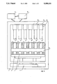
- FIG. 1 is a general schematic view of an apparatus according to the the invention
- FIG. 2 is a front view, with some details cross-sectioned and other details omitted for the sake of clarity, of a plug gauge device of the apparatus of FIG. 1,
- FIG. 3 is a cross-section of a detail of the device of FIG. 2, along line III--III of FIG. 2, with the omission of some elements,
- FIGS. 4, 5 and 6 are cross-sections of the device of FIG. 2 along lines IV--IV, V--V and VI--VI of FIG. 2, in which some details are omitted for the sake of clarity, and
- FIG. 7 is a side view of a detail of the device of FIG. 2.
- FIG. 1 schematically shows the structure of an apparatus according to the invention, with a support body 1 and support means comprising a support and reference platform 2 for supporting and positioning a part 3 to be checked.
- Part 3 for example the motor block of a six-cylinder engine, also schematically shown in the figure, comprises six cylindrical seats with cylinder liners 4,5, 6,7,8 and 9, and a seat 10 for the driving shaft.
- Measuring devices or plug gauges 11,12,13,14,15 and 16 are secured to support body 1, in positions such that the plug gauges are arranged along parallel longitudinal axes, substantially coinciding with the longitudinal axes defined by the corresponding liners 4-9 of motor block 3.
- Support body 1 and support means 2 can perform mutual longitudinal translations for displacing each plug gauge 11-16 into cooperation with the corresponding liner 4-9.
- support means 2 can, for example, translate upwards and thus displace part 3 towards plug gauges 11-16, by first actuating means of known type, schematized in FIG. 1 and denoted by reference numeral 17.
- Positioning and locking devices 18 and 19 are secured to support body 1 and permit the locking and unlocking of two of said plug gauges, 15 and 16. In this way, the measuring apparatus can easily and quickly be adapted for checking a four-cylinder or five-cylinder motor block, while, vice versa, the addition of one or both the plug gauges 15 and 16 can be made in accurate and equally simple and quick way, for checking again a motor block 3 like that illustrated.
- the devices 18 and 19 include known positioning and locking elements and are not shown in detail in the figures.
- plug gauge 11-16 The structure of the six plug gauges 11-16 is substantially the same and consequently the following description is referred, as an example, to only one of them, plug gauge 11, shown in FIGS. 2 to 7.
- FIG. 2 shows plug gauge 11 housed within the corresponding liner 4 of motor block 3, as a consequence of the approach, along the longitudinal direction, between support means 2 and body 1.
- a frame 20 is directly coupled to support body 1 and includes a support plate 21 having a central opening 22. As shown, in connection with plug gauges 15 and 16, the relevant frames 20 are fixed to the above mentioned devices 18 and 19.
- Coupling means comprise four elongate elements or shafts 29,30,31 and 32, having at their ends conical seats or "centres", and arranged--between corresponding pairs of centre points coupled to plates 21 and 27 and cooperating with the conical seats--parallel to one another in positions substantially coinciding with four generating lines, at 90° from one another, of a geometric cylindrical surface defining a longitudinal central axis.
- each shaft for example shaft 29, comprises a conical seat or centre 33, which is engaged by a centre point 34 coupled to circular plate 27 by a threaded coupling, and a conical seat 35 that cooperates with a second centre point 36.
- the second centre point 36 is coupled to plate 21 through a coupling element 37 including an integral fulcrum 38 (FIG. 3), so as to apply an axial resilient thrust to shaft 29 towards first point 34, and define the longitudinal position of the same shaft 29, by eliminating any clearance, also in view of possible wear.
- the particular coupling of shafts 29-32 to plates 21 and 27 permits the same shafts to perform rotations about their longitudinal geometric axes.
- Datums 40-43 are made and arranged so that rotations of each shaft (for example of shaft 29 about the axis defined by the relevant centre points) cause rotations of the relevant datum (40) about the same axis, that cause the contacting portion to move away from, or approach the surface of liner 4 along a transversal arc, and to contact said surface along a direction substantially perpendicular to the same surface.
- Transducer means 52,53,54 and 55 coupled to frame 20, are arranged to cooperate with shafts 29-32 and to provide electric signals indicative of the angular positions of these shafts 29-32.
- a processing and display unit schematically shown in FIG. 1 and denoted by reference numeral 58, is connected to transducer means 52-55 and processes said electric signals for obtaining diametral measurements of liner 4.
- the transducer means can comprise, for example,--as shown in the figures--four differential transducers 52-55 connected as follows.
- Each of transducers 52-55 comprises two mutually movable parts, in particular windings 56 fixed to one of the stationary supports 44-47 and a core 57 coupled to the corresponding rotatable support 48-51.
- Second actuating means comprise actuating devices of passive type, i.e. not motorized.
- actuating devices of passive type, i.e. not motorized.
- each pair of stationary and rotatable supports 44-47 and 48-51 are coupled the two ends of a return spring 59, which pulls towards each other said stationary and rotatable supports, by applying to the corresponding shaft 29-32 a rotation moment.
- the second actuating means also comprise retraction means with four datum bars 60,61,62 and 63, each of which is secured transversely, to one of shafts 29-32.
- Two reference elements or cones 64 and 65 are fixed to plate 21 and arranged with the axes parallel to shafts 29-32. Cones 64,65 can be displaced along their axes so as to take two positions.
- the general arrangement of the retraction means --which include bars 60-62 and cones 64,65-- is such that the surface of each cone 64 (65) is into contact with a pair of bars 60,61 (62,63) and in this way limits the angular displacements of the corresponding pair of shafts 29,30 (31,32) caused by springs 59.
- the retraction means can be made in different way, for example to include a single reference cone centrally arranged, that cooperates with all of the four bars 60-63 to control by a single motion the rotation of the four shafts 29-32.
- Eight checking heads are coupled by pairs 70,71 to each shaft 29-32 by locking elements of "tie" type.
- heads 70,71 comprises a stationary part, a movable part carrying a feeler element 78 adapted to contact the surface of liner 4, fulcrum means for permitting mutual displacements between the movable and the stationary part, and a transducer device electrically connected to unit 58 for providing an electric signal depending on the position taken by the movable part as a consequence of the contact between feeler 78 and the surface to be checked.
- heads 70,71 comprise means with deformable fulcrums and transducer devices providing electrical signals responsive to said deformations, for example as described in international application published with No. WO-A-8903507.
- heads 70,71 on shafts 29-32 permits the relevant feelers 78--in correspondence with suitable angular positions of shafts 29-32 defined, substantially, by the contact between relevant datums 40-43 and the surface of liner 4--to touch the surface of liner 4 on two cross-sections, substantially in four points, arranged at 90° from one another, of each cross-section.
- Two cylindrical nosepieces 80,81 are fixed to lower first ends of corresponding longitudinal bars 82,83, belonging to further coupling means.
- Bars 82,83 are partially housed within plug gauge 11, i.e. in substance between uprights 23-26 and shafts 29-32, pass through opening 28 of plate 27 next to said first ends, and pass through opening 22 of plate 21 next to the upper opposed ends, which are secured to the same plate 21 by elements 84,85 with integral fulcrums.
- Elements 84 and 85 with integral fulcrums define mutually parallel transversal axes for the rotation of bars 82 and 83 and, consequently, of nosepieces 80 and 81.
- Each of nosepieces 80 and 81 comprises, on the cylindrical side surface, four elongate seats for housing measuring means, in particular further checking heads or, more exactly, comparative gauging heads 86,87,88 and 89, shown in FIG. 7 and including relevant stationary parts, movable parts carrying feelers, fulcrum means and transducer devices electrically connected to unit 58.
- the further heads 86-89 are made, for example, as described in international application published under No. WO-A-8903507.
- each of the two nosepieces 80 and 81 are arranged so that, after said nosepieces are inserted, through liner 4, into the seat 10 for the motor shaft, the relevant feelers enter into contact with the surface of said seat 10, on two cross-sections perpendicular to the axis of seat 10, oppositely arranged with respect to the geometric axis of liner 4, substantially in four points of this cross-section arranged at 90° from one another.
- Nosepieces 80 and 81 are sealingly closed and are connected to a pneumatic circuit (not shown in the figures), controlling, by intake of air from the nosepiece and consequent depression within the same nosepiece, movements of withdrawal or retraction of the movable parts of heads 86-89, for moving the relevant feelers away from a checking position and permitting entering of the nosepieces into seat 10 of the motor shaft.
- a pneumatic circuit not shown in the figures
- FIG. 2 shows only one of the further actuating means 90, while only one (83) of the two bars and the relevant nosepiece (81) are in the position for checking the hole 10, and bar 82 and nosepiece 80 are retracted to a rest position.
- a control unit denoted in FIG. 1 by reference numeral 99, is connected to processing unit 58 and to the first, second and further actuating means for automatically controlling the displacements of the various elements of the apparatus.
- each plug gauge 11-16 By acting, through control unit 99, on the retraction means of each plug gauge 11-16, i.e. by causing upward axial displacements of cones 64,65, shafts 29-32 are caused to rotate, due to the action of springs 59, in such a way that datums 40-43 and feeler elements 78 of checking heads 70,71 remain within the plug gauge, namely within a transversal space defined in substance by the dimensions of plate 27.
- Actuating means 90 through a pneumatic circuit connected to control unit 99 and not shown in the figure, control the rotation of bars 82 and 83 in such a way that also nosepieces 80 and 81 remain within said space, while the pneumatic circuit also controls the retraction of the further heads 86-89 of each nosepiece 80,81.
- a new actuation of the retraction means causes axial displacements of cones 64 and 65 in the direction opposite to the preceding one, so that, due to the action of springs 59, shafts 29-32 rotate until datums 40-43 contact corresponding points of liner 4.
- the zero-setting or calibration of the apparatus as to the checkings relating to the liner 4 is carried out in this condition.
- the position of checking heads 70,71 on shafts 29-32 is--during this phase--adjusted and locked by the tie elements so that the corresponding feelers 78 surely enter, before datums 40-43, into contact with the surface of liner 4.
- the procedure for arranging part 3 in the checking position is quite similar to that described in connection with the master.
- the actuation of the retraction means causes the displacement of cones 64 and 65 in axial direction, towards plate 21, and consequently shafts 29-32, due to the action of springs 59, rotate until datums 40-43 contact corresponding points of liner 4.
- Transversal dimensions of liner 4 are checked depending on the signals provided by transducers 52-55 in the condition when the four datums 40-43 contact liner 4.
- the signals provided by transducers 52-55 to processing unit 58 are indicative of the deviations of the transversal dimensions of the part from those of the master.
- the signals provided by checking heads 70,71, in correspondence with the angular position of shafts 29-32 defined by said contact between datums 40-43 and the surface of liner 4, are processed in unit 58 for obtaining derived measurements relating to concentricity and/or straightness errors of the cylindrical surface of liner 4.
- derived measurements relating to concentricity and/or straightness errors of the cylindrical surface of liner 4. from the signals of four heads 70 measuring in the same cross-section it is possible to obtain, for example, the transversal deviation of the centre of said cross-section from the centre of the corresponding cross-section of the master and/or from the centre of the cross-section defined by datums 40-43, in order to obtain information as to the so-called concentricity of the cylindrical surface.
- each plug gauge 11-16 of four transducers 52-55 connected to unit 58 and, above all, the rotation movements of heads 70,71--together with shafts 29,32--from and towards the surfaces to be checked, permit the use of a compact apparatus having small overall dimensions for checking parts in a wide measuring range; moreover, the angularly adjustable coupling of datums 40-43 70,71 to shafts 29-32 permit a sufficiently quick retooling for checking parts having dimensions considerably different.
- the possibility of using six plug gauges 11-16 or--by a simple and quick modification--only four or five 11-14 of them, as already explained, contributes to the considerable flexibility of use of the apparatus.
- the number of checking heads 70,71 coupled to shafts 29-32 can be increased or decreased with respect to what has been illustrated, depending on the type of checking to be performed and/or the major or minor precision required for a determined checking.
- Heads 70,71 for example, can be fixed to only two opposed shafts 29 and 31, according to the simplified showing of FIG. 5.
- the above described heads 70,71 can be replaced by a different type of heads adapted to carry out similar measurements, for example pneumatic heads, also coupled to shafts 29-32 in an axially and angularly adjustable way and rotatable with said shafts 29-32.
- the transducer means 52-55 that according to the example of the figures are constituted by transducers of differential type, can generally be made in different way, for example as angular transducers of optical type.
- actuating means 90 control the rotation of bars 82,83 and the consequent insertion of nosepieces 80,81 into the seat 10 for the motor shaft, in a checking position defined by stop elements 95,96.
- the feelers of heads 86-89 after the releasing of the pneumatic retraction preventing mechanical interferences in the phase of insertion, contact the surface of seat 10 in correspondence with determined cross-sections; the transducer devices of the same heads 86-89 provide electrical signals that, by processing in unit 58, permit the measurement of diameters of seat 10.
Landscapes
- Physics & Mathematics (AREA)
- General Physics & Mathematics (AREA)
- A Measuring Device Byusing Mechanical Method (AREA)
- Length Measuring Devices With Unspecified Measuring Means (AREA)
- Paper (AREA)
- Laying Of Electric Cables Or Lines Outside (AREA)
Applications Claiming Priority (2)
| Application Number | Priority Date | Filing Date | Title |
|---|---|---|---|
| IT3380A/90 | 1990-03-08 | ||
| IT00338090A IT1238193B (it) | 1990-03-08 | 1990-03-08 | Apparecchio per il controllo multiplo di dimensioni interne. |
Publications (1)
| Publication Number | Publication Date |
|---|---|
| US5259121A true US5259121A (en) | 1993-11-09 |
Family
ID=11106045
Family Applications (1)
| Application Number | Title | Priority Date | Filing Date |
|---|---|---|---|
| US07/768,747 Expired - Fee Related US5259121A (en) | 1990-03-08 | 1991-02-22 | Apparatus for a multiple checking of internal dimensions |
Country Status (6)
| Country | Link |
|---|---|
| US (1) | US5259121A (it) |
| EP (1) | EP0476077B1 (it) |
| JP (1) | JPH04505216A (it) |
| DE (1) | DE69103501T2 (it) |
| IT (1) | IT1238193B (it) |
| WO (1) | WO1991014152A1 (it) |
Cited By (7)
| Publication number | Priority date | Publication date | Assignee | Title |
|---|---|---|---|---|
| WO1999015853A1 (en) * | 1997-09-25 | 1999-04-01 | Daros Holding Ab | Device for determining the internal measurements of cylinder linings |
| US6427353B1 (en) * | 1998-05-28 | 2002-08-06 | Rockwell Automation Technologies, Inc. | High speed acquisition and calculation of dimensional variables with vibration and skew error reduction |
| US6843125B2 (en) | 2002-01-08 | 2005-01-18 | Robert Peterson | Fluid-aligned measurement apparatus and method |
| US20050022408A1 (en) * | 2003-07-31 | 2005-02-03 | Wendt Noel D. | Container plug gauge and method of use |
| US20070193050A1 (en) * | 2004-10-01 | 2007-08-23 | Guido Golinelli | Apparatus for dimensional and/or geometric checking of mechanical parts |
| US20100251558A1 (en) * | 2009-04-06 | 2010-10-07 | The Boeing Company | Concentricity sensor and methods of use and application |
| US20130192076A1 (en) * | 2010-11-09 | 2013-08-01 | Mitsubishi Heavy Industries, Ltd. | Hole examining device |
Families Citing this family (1)
| Publication number | Priority date | Publication date | Assignee | Title |
|---|---|---|---|---|
| CN114791260B (zh) * | 2022-04-29 | 2023-01-06 | 佛山市天劲新能源科技有限公司 | 一种电池箱体安装用孔位检测装置 |
Citations (11)
| Publication number | Priority date | Publication date | Assignee | Title |
|---|---|---|---|---|
| US2659157A (en) * | 1949-05-04 | 1953-11-17 | Sheffield Corp | Size gauging device for v type cylinder blocks |
| DE3024334A1 (de) * | 1980-06-27 | 1982-01-21 | Ludwig Dr.-Ing. 7500 Karlsruhe Pietzsch | Verfahren und vorrichtung zum vermessen der innenkontur von bohrungen |
| US4338726A (en) * | 1980-07-14 | 1982-07-13 | Swailes Charles W | Line bore gauge |
| US4393698A (en) * | 1980-06-27 | 1983-07-19 | Ludwig Pietzsch | Device for measuring hollow cylinder surfaces |
| US4412385A (en) * | 1981-01-27 | 1983-11-01 | Finike Italiana Marposs S.P.A. | Gauge for checking features - like linear dimensions - of a mechanical piece |
| CH639753A5 (en) * | 1979-09-11 | 1983-11-30 | Meseltron Sa | Measuring device for measuring diameters of cylindrical bores |
| WO1986002996A1 (fr) * | 1984-11-15 | 1986-05-22 | Elgema Gmbh | Dispositif de mesure du profil de surfaces cylindriques de pieces a usiner |
| GB2167862A (en) * | 1984-12-01 | 1986-06-04 | Sigma Ltd | Component inspection apparatus |
| DE3533239A1 (de) * | 1985-09-18 | 1987-03-26 | Rheinmetall Gmbh | Messeinrichtung |
| US4872269A (en) * | 1988-04-08 | 1989-10-10 | Karl Sattmann | Automatic cylinder profiling gage |
| US4986004A (en) * | 1989-01-04 | 1991-01-22 | Pat Messtechnik Gmbh | Method and apparatus for measuring the configuration of cylinder bores in workpieces |
Family Cites Families (2)
| Publication number | Priority date | Publication date | Assignee | Title |
|---|---|---|---|---|
| JPS51103463A (ja) * | 1975-03-10 | 1976-09-13 | Toyoda Machine Works Ltd | Anasokuteisochi |
| JPS58122405A (ja) * | 1981-09-18 | 1983-07-21 | Mitsubishi Heavy Ind Ltd | 内径測定装置 |
-
1990
- 1990-03-08 IT IT00338090A patent/IT1238193B/it active IP Right Grant
-
1991
- 1991-02-22 JP JP3504211A patent/JPH04505216A/ja active Pending
- 1991-02-22 WO PCT/EP1991/000335 patent/WO1991014152A1/en not_active Ceased
- 1991-02-22 EP EP91904396A patent/EP0476077B1/en not_active Expired - Lifetime
- 1991-02-22 US US07/768,747 patent/US5259121A/en not_active Expired - Fee Related
- 1991-02-22 DE DE69103501T patent/DE69103501T2/de not_active Expired - Fee Related
Patent Citations (11)
| Publication number | Priority date | Publication date | Assignee | Title |
|---|---|---|---|---|
| US2659157A (en) * | 1949-05-04 | 1953-11-17 | Sheffield Corp | Size gauging device for v type cylinder blocks |
| CH639753A5 (en) * | 1979-09-11 | 1983-11-30 | Meseltron Sa | Measuring device for measuring diameters of cylindrical bores |
| DE3024334A1 (de) * | 1980-06-27 | 1982-01-21 | Ludwig Dr.-Ing. 7500 Karlsruhe Pietzsch | Verfahren und vorrichtung zum vermessen der innenkontur von bohrungen |
| US4393698A (en) * | 1980-06-27 | 1983-07-19 | Ludwig Pietzsch | Device for measuring hollow cylinder surfaces |
| US4338726A (en) * | 1980-07-14 | 1982-07-13 | Swailes Charles W | Line bore gauge |
| US4412385A (en) * | 1981-01-27 | 1983-11-01 | Finike Italiana Marposs S.P.A. | Gauge for checking features - like linear dimensions - of a mechanical piece |
| WO1986002996A1 (fr) * | 1984-11-15 | 1986-05-22 | Elgema Gmbh | Dispositif de mesure du profil de surfaces cylindriques de pieces a usiner |
| GB2167862A (en) * | 1984-12-01 | 1986-06-04 | Sigma Ltd | Component inspection apparatus |
| DE3533239A1 (de) * | 1985-09-18 | 1987-03-26 | Rheinmetall Gmbh | Messeinrichtung |
| US4872269A (en) * | 1988-04-08 | 1989-10-10 | Karl Sattmann | Automatic cylinder profiling gage |
| US4986004A (en) * | 1989-01-04 | 1991-01-22 | Pat Messtechnik Gmbh | Method and apparatus for measuring the configuration of cylinder bores in workpieces |
Cited By (11)
| Publication number | Priority date | Publication date | Assignee | Title |
|---|---|---|---|---|
| WO1999015853A1 (en) * | 1997-09-25 | 1999-04-01 | Daros Holding Ab | Device for determining the internal measurements of cylinder linings |
| US6427353B1 (en) * | 1998-05-28 | 2002-08-06 | Rockwell Automation Technologies, Inc. | High speed acquisition and calculation of dimensional variables with vibration and skew error reduction |
| US6843125B2 (en) | 2002-01-08 | 2005-01-18 | Robert Peterson | Fluid-aligned measurement apparatus and method |
| US20050022408A1 (en) * | 2003-07-31 | 2005-02-03 | Wendt Noel D. | Container plug gauge and method of use |
| US6871415B2 (en) * | 2003-07-31 | 2005-03-29 | Owens-Brockway Glass Container Inc. | Container plug gauge and method of use |
| US20070193050A1 (en) * | 2004-10-01 | 2007-08-23 | Guido Golinelli | Apparatus for dimensional and/or geometric checking of mechanical parts |
| US7412778B2 (en) * | 2004-10-01 | 2008-08-19 | Marposs Societa' Per Azioni | Apparatus for dimensional and/or geometric checking of mechanical parts |
| US20100251558A1 (en) * | 2009-04-06 | 2010-10-07 | The Boeing Company | Concentricity sensor and methods of use and application |
| US7937849B2 (en) * | 2009-04-06 | 2011-05-10 | The Boeing Company | Concentricity sensor and methods of use and application |
| US20130192076A1 (en) * | 2010-11-09 | 2013-08-01 | Mitsubishi Heavy Industries, Ltd. | Hole examining device |
| US9212881B2 (en) * | 2010-11-09 | 2015-12-15 | Mitsubishi Heavy Industries, Ltd. | Hole examining device |
Also Published As
| Publication number | Publication date |
|---|---|
| IT9003380A0 (it) | 1990-03-08 |
| WO1991014152A1 (en) | 1991-09-19 |
| EP0476077A1 (en) | 1992-03-25 |
| EP0476077B1 (en) | 1994-08-17 |
| IT9003380A1 (it) | 1991-09-08 |
| DE69103501D1 (de) | 1994-09-22 |
| IT1238193B (it) | 1993-07-09 |
| JPH04505216A (ja) | 1992-09-10 |
| DE69103501T2 (de) | 1995-02-23 |
Similar Documents
| Publication | Publication Date | Title |
|---|---|---|
| US5542188A (en) | Measuring apparatus for checking the dimensions of cylindrical workpieces | |
| CN104822492B (zh) | 用于测量工件的工具机和方法 | |
| US4447959A (en) | Instrument for measuring internal dimensions | |
| US4800652A (en) | Machine for measuring generally circular objects in cylindrical coordinates | |
| US5778551A (en) | Coordinate measuring apparatus having a device for profile measurements and method for making said profile measurements | |
| EP2889573B1 (en) | Motorized inclinable measuring head | |
| JP6208844B2 (ja) | 測定対象物の形状輪郭を割り出す方法 | |
| EP2601476B1 (en) | Calibration device for measurement gauges of the diameter and other geometrical characteristics of cylinders | |
| US5461797A (en) | Object measuring system | |
| CN202101656U (zh) | 双测头结构 | |
| JPH07109361B2 (ja) | 割出し機構 | |
| US9714881B2 (en) | Method and device for determining a machining axis | |
| US11754387B2 (en) | Noncontact sensor calibration using single axis movement | |
| EP2957383A1 (en) | Machine tool | |
| EP0157176B1 (en) | An apparatus for measuring dimensions, in particular diametral and axial dimensions of parts with rotational symmetry | |
| US5259121A (en) | Apparatus for a multiple checking of internal dimensions | |
| CN205192431U (zh) | 阀芯阀套参数自动检测装置 | |
| US3798779A (en) | Probe inspection system | |
| JP3564106B2 (ja) | 真円測定方法および真円測定装置 | |
| EP3189302B1 (en) | Coordinate measuring method and apparatus for inspecting workpieces, comprising generating measurement correction values using a reference shape that is known not to deviate substantially from a perfect form | |
| CN109282727B (zh) | 一种用于等直径深孔检测的气式内径量具 | |
| US4062124A (en) | Apparatus for measuring errors in concentricity relative to two surfaces of rotation | |
| CN219914378U (zh) | 一种零件圆度测量装置 | |
| CN117906458A (zh) | 一种盘齿轮分度圆半径自动测量仪及其使用方法 | |
| CN114459379A (zh) | 五轴柔性检测平台及检测方法 |
Legal Events
| Date | Code | Title | Description |
|---|---|---|---|
| AS | Assignment |
Owner name: MARPOSS SOCIETA' PER AZIONI, ITALY Free format text: ASSIGNMENT OF ASSIGNORS INTEREST.;ASSIGNORS:MANFREDI, GABRIELLA;POSSATI, ALBERTO;POSSATI, EDOARDO;AND OTHERS;REEL/FRAME:006349/0614;SIGNING DATES FROM 19911011 TO 19911014 |
|
| CC | Certificate of correction | ||
| FEPP | Fee payment procedure |
Free format text: PAYOR NUMBER ASSIGNED (ORIGINAL EVENT CODE: ASPN); ENTITY STATUS OF PATENT OWNER: LARGE ENTITY |
|
| FPAY | Fee payment |
Year of fee payment: 4 |
|
| REMI | Maintenance fee reminder mailed | ||
| REMI | Maintenance fee reminder mailed | ||
| LAPS | Lapse for failure to pay maintenance fees | ||
| STCH | Information on status: patent discontinuation |
Free format text: PATENT EXPIRED DUE TO NONPAYMENT OF MAINTENANCE FEES UNDER 37 CFR 1.362 |
|
| FP | Lapsed due to failure to pay maintenance fee |
Effective date: 20011109 |