US5218625A - Method for the automatic determination of the exposure time of a radiographic film and system of implementation thereof - Google Patents
Method for the automatic determination of the exposure time of a radiographic film and system of implementation thereof Download PDFInfo
- Publication number
- US5218625A US5218625A US07/726,205 US72620591A US5218625A US 5218625 A US5218625 A US 5218625A US 72620591 A US72620591 A US 72620591A US 5218625 A US5218625 A US 5218625A
- Authority
- US
- United States
- Prior art keywords
- sub
- film
- exposure
- mas
- calculating
- Prior art date
- Legal status (The legal status is an assumption and is not a legal conclusion. Google has not performed a legal analysis and makes no representation as to the accuracy of the status listed.)
- Expired - Lifetime
Links
- 238000000034 method Methods 0.000 title claims abstract description 89
- 230000003287 optical effect Effects 0.000 claims abstract description 66
- 238000005259 measurement Methods 0.000 claims abstract description 41
- 238000001514 detection method Methods 0.000 claims abstract description 32
- 238000005286 illumination Methods 0.000 claims description 16
- 230000000694 effects Effects 0.000 claims description 12
- 238000012937 correction Methods 0.000 claims description 7
- 238000006243 chemical reaction Methods 0.000 claims description 6
- 238000001914 filtration Methods 0.000 claims description 6
- 238000010438 heat treatment Methods 0.000 claims description 2
- 230000006870 function Effects 0.000 description 60
- 230000005855 radiation Effects 0.000 description 9
- 238000001228 spectrum Methods 0.000 description 9
- 238000012360 testing method Methods 0.000 description 6
- 230000010354 integration Effects 0.000 description 5
- 238000012986 modification Methods 0.000 description 4
- 230000004048 modification Effects 0.000 description 4
- 230000004044 response Effects 0.000 description 3
- 230000008901 benefit Effects 0.000 description 2
- 230000008859 change Effects 0.000 description 2
- 238000011161 development Methods 0.000 description 2
- 230000018109 developmental process Effects 0.000 description 2
- 238000010586 diagram Methods 0.000 description 2
- 238000004846 x-ray emission Methods 0.000 description 2
- 238000010521 absorption reaction Methods 0.000 description 1
- 230000009471 action Effects 0.000 description 1
- 230000032683 aging Effects 0.000 description 1
- 238000013459 approach Methods 0.000 description 1
- 230000003247 decreasing effect Effects 0.000 description 1
- 238000003745 diagnosis Methods 0.000 description 1
- 238000009607 mammography Methods 0.000 description 1
- 238000002601 radiography Methods 0.000 description 1
Images


Classifications
-
- A—HUMAN NECESSITIES
- A61—MEDICAL OR VETERINARY SCIENCE; HYGIENE
- A61B—DIAGNOSIS; SURGERY; IDENTIFICATION
- A61B6/00—Apparatus or devices for radiation diagnosis; Apparatus or devices for radiation diagnosis combined with radiation therapy equipment
- A61B6/58—Testing, adjusting or calibrating thereof
- A61B6/582—Calibration
- A61B6/583—Calibration using calibration phantoms
-
- H—ELECTRICITY
- H05—ELECTRIC TECHNIQUES NOT OTHERWISE PROVIDED FOR
- H05G—X-RAY TECHNIQUE
- H05G1/00—X-ray apparatus involving X-ray tubes; Circuits therefor
- H05G1/08—Electrical details
- H05G1/26—Measuring, controlling or protecting
- H05G1/30—Controlling
- H05G1/46—Combined control of different quantities, e.g. exposure time as well as voltage or current
Definitions
- the invention relates to radiology systems that have a radiological film and are used to examine objects and, more particularly in such systems, it relates to a method that enables the estimation, while the object is being examined, of the "lumination” or "luminous exposure” (i.e. the quantity of light received multiplied by the exposure time) to which the radiological film is subjected, and enables the stopping of the exposure when the film has reached a given level of blackening or optical density.
- a radiology system essentially comprises an X-ray tube and a receiver of such radiation, between which the object to be examined, for example a part of a patient's body, is interposed.
- the image receiver which is, for example, a film/screen couple, gives an image of the object after an appropriate exposure time and the development of the film.
- the different dots that constitute it should have sufficient contrast with respect to one another, namely, the blackening of the radiographic film should be appropriate from one X-ray image to the next one, despite the possible differences in opacity of the radiographed object.
- the blackening of the film is related to the quantity of energy of the radiation incident to the film/screen couple, namely, the product of the intensity of the radiation to which the radiographic film is subjected, or "film" dose rate, by the time during which the film is exposed to this radiation. Consequently, to obtain a constant blackening of the film from one radiography to another, there is a known way of making measurements, during the examination, of the incident energy on the film by means of a detection cell, generally placed before the receiver, that is sensitive to X-radiation and gives a current proportional to the "film” dose rate. This current is integrated, from the start of the exposure, in an integrator circuit that gives an increasing value during the exposure.
- This increasing value is compared, during the exposure time, with a fixed reference value, established beforehand as a function of the characteristics of the film.
- the end of the exposure time is determined by the instant at which the comparison indicates that the value representing the incident energy on the film is equal to the reference value.
- the blackening of the film depends on the quality of the spectrum.
- the response of the screen depends on the energy distribution of the spectrum of the radiation received, which means that it is sensitive to the hardening of the spectrum and to the change in voltage of the X-ray tube.
- the detection cell is placed before the film (for example in mammography) for the radiation energy is such that the detection cell would then be visible on the film.
- the detection cell is placed behind the image receiver but this creates an additional difficulty for the signal perceived by the detector cell is the one that has not contributed to the blackening of the film. The result thereof is that the measurement made by the detection cell does not generally represent the incident lumination on the radiographic film.
- this correction does not take account of the effects of other phenomena such as the hardening of the X-radiation due to the thickness of the object crossed and the modification of the spectrum due to the voltage of the X-ray tube.
- the detection cell is placed before the image receiver.
- An object of the present invention is to implement a method for the automatic determination, during the time of exposure, of the instant when the exposure is stopped, taking account of the different effects that come into play, notably the variations in the tube current, the hardening of the spectrum due to the thickness of the object crossed, the modification of the spectrum due to the voltage of the tube and, when an intensifier screen is present, the absorption response of said screen.
- the invention relates to a method for automatically determining the exposure time of a radiographic film in a radiology system designed, to examine an object that includes an X-ray tube having a supply voltage V which may assume various values, V m , with continuous or discrete variation.
- the X-ray tube emits an X-ray beam in the form of pulses of variable duration S towards the object to be examined.
- a receiver detects the X-radiation that has crossed the object, to form an image of said object.
- the receiver is constituted by at least one intensifier screen and a film sensitive to the light emitted by this screen.
- a cell detects the X-rays that have crossed the object, to be examined and is placed behind the image receiver to enable the conversion of a physical variable, characterizing the X-ray beam, into a measurement signal L.
- An integrator circuit integrates the measurement signal L for, the duration S of the exposure and produces a signal M a device computes the yield D given by determining the ratio of M to the product I ⁇ S (or mA ⁇ s) of the anode current I of the tube by the duration S of the exposure.
- the method includes the following operations.
- the step (e8) further includes the calculating of the mA ⁇ s delivered (mAs c ) during the steps (e4) to (e8) defined by the equation:
- the step (e10) further includes a step of computing the remaining exposure time, such that ##EQU1## so as to end the exposure in an open loop if t rc is smaller than a value t" corresponding to the interval of time between two successive operations (e3).
- steps (e3) to (e10) are replaced by:
- T.E. a task of estimation (T.E.) of the mA ⁇ s remaining to be delivered, constituted by the steps (e4) to (e8) and a step of converting the mA ⁇ s into a signal in the units of the cell 12 such that:
- T.C. a task of interrupting (T.C.) the exposure which consists in decrementing the target value CE target by the signals received by the cell (12) and in terminating the exposure when the decremented value becomes smaller than or equal to a value Val o (Val o is equal to zero for example).
- T.E. The task of estimation (T.E.) is renewed periodically during the exposure at the instants t 1 , t 2 . . . t n separated by a period that is at least equal to the computation time t c .
- step (e10) is replaced by the step of computing the remaining exposure time t rc so as to end the exposure in an open loop.
- CNRD film dose rate
- the coefficient CNRD (film dose rate) is obtained by performing the following steps of :
- the film dose rate d i is given, for example, by the formula: ##EQU3##
- the reference lumination L ref is determined by a calibration method that includes the following steps of (or operations for) :
- the coefficients of non-reciprocity CNRT (t i ) as a function of the exposure time (t i ) may be obtained in different ways, for example by performing the following steps of :
- the coefficients CNRT (t i ) may be modelized by the function :
- FIG. 1 is a block diagram of a radiology system enabling the implementation of the method according to the invention
- FIG. 2 is a graph showing curves obtained by implementing a method of calibration used in the method according to the invention
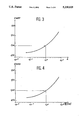
- FIG. 3 is a graph showing a curve of variation of the coefficients of non-reciprocity CNRT as a function
- FIG. 4 is a graph showing curves of variation of the coefficients of non-reciprocity CNRD as a function of the inverse of the film dose rate d,
- FIG. 5 is a graph showing curves of variation of the optical density of a radiographic film as a function of the lumination
- FIG. 6 is a block diagram of a radiology system, similar to the one of FIG. 1 but in which the detection cell is incorporated in the receiver and is subject to light emitted by the screen.
- a radiology system to which the method, according to the invention, for the automatic determination of the exposure time of an object 13 to be radiographed, can be applied comprises an X-ray source 11 such as an X-ray tube that gives an X-ray beam illuminating this object 13 and an image receiver 17 such as a film/intensifier screen couple that is positioned so as receive the X-rays having crossed said object and that gives an image of the object 13 after an appropriate exposure time S and development of the film.
- an X-ray source 11 such as an X-ray tube that gives an X-ray beam illuminating this object 13
- an image receiver 17 such as a film/intensifier screen couple that is positioned so as receive the X-rays having crossed said object and that gives an image of the object 13 after an appropriate exposure time S and development of the film.
- the system further includes a detection cell 12, that is placed behind the image receiver 17 in the case of a radiographic film with an intensifier screen. This cell may be placed in front of the receiver in the case of a film without an intensifier screen.
- the detection cell 12 enables the conversion of a physical variable characteristic of the X-radiation that has crossed the object and the image receiver, such as the KERMA or the energy fluence into a measurement signal L, for example of the electrical type.
- the signal L, produced by the detection cell 12 is applied to a circuit 16 that carries out an integration of the electrical signal during the duration S of the exposure.
- the signal M that results from the integration is a measurement of the radiation that has crossed the object 13 during the duration S of the exposure.
- the X-radiation source 11 is associated with a power supply 15 that produces a variable high voltage V m for the X-ray tube and includes an instrument for the measurement of the anode current I of said tube.
- the power supply device 15 and the X-ray tube include means to start the X-ray emission at a precise,. instant and to stop it after a variable time S.
- Time s is determined, in accordance with the invention, as a function of the signal M produced by the circuit 16 and of the values of I, S and V m and, more precisely, of the ratio M/I ⁇ S which is called the yield D and is computed by the device 18.
- the values of the yield D are processed by a computer or microprocessor 19 in accordance with the method of the invention so as to give an end-of-exposure signal.
- the first operation of the method consists of performing a calibration of the radiology system of FIG. 1 that leads to a function of estimation of the lumination received by the radiographic film.
- This calibration and the function of estimation are described in the French patent application filed on the same date and entitled: METHOD FOR THE ESTIMATION AND CALIBRATION OF THE LUMINATION RECEIVED BY A RADIOGRAPHIC FILM corresponding to U.S. Pat. application Ser. No. 07/726,204, filed Jul. 5, 1991.
- the method for estimating the lumination received by a radiographic film is based on calibration operations that result in the definition of a function that is proportional to the dose rate of photons on to the film, called the film dose rate, and on a calibration that can be used to establish the relationship between the film dose rate function and the lumination received by the film under fixed reference conditions and results in a given blackening of the film.
- This latter calibration shall be described in fuller detail hereinafter in the description.
- the calibrations that enable a definition of a film dose rate function are derived from a calibration method described in U.S. patent application Ser. No. 07/535 520 filed on Jun. 8, 1990 and entitled: METHOD FOR THE CALIBRATION OF A RADIOLOGICAL SYSTEM AND FOR THE MEASUREMENT OF THE EQUIVALENT THICKNESS OF AN OBJECT.
- This method consists of measuring the yield D of the cell for each standard at the chosen supply voltages V m . More precisely, with a first thickness standard E 1 , a measurement of yield D 1m is made for each value V m constituting a determined set. These values D 1m as a function of the voltage V m may be entered in a graph to obtain the points 21' of FIG. 2.
- the yields D pm have been entered as logarithmic y-axis values while the supply voltages have been entered as x-axis values from 20 kilovolts to 44 kilovolts.
- the parameters of the analytical model may be adjusted by means of standard estimation tools such as the minimal mean square error method.
- the curves 21 to 25 represent the value of the yield D given by the analytical model represented by the expression :
- This calibration is performed twice with configurations of the radiology system that differ as regards the receiver 17.
- the first of these calibration operations is done with the receiver 17 without an intensifier screen.
- a function f' is determined, giving rise to yield values of the cell 12 referenced D se such that:
- the second operation of the method consists of performing a second calibration provided with a receiver 17 including an intensifier screen and then a series of yield values D c is obtained and, as above, the function f" is determined such that:
- This function D f does not take account of the modification of the spectrum of the X-radiation due to the additional filtration between the intensifier screen and the detection cell 12 that comes, for example, from the output face of the cartridge containing the film/screen couple.
- E p in the equation (8) is replaced by (E p -sup.filter) where sup.filter is the thickness equivalent to the radiographed object corresponding to this filtration.
- This equivalent thickness is obtained by placing, for example, in the beam 14, an object equivalent to this filtration and by using the calibrated function determining the equivalent thickness g' or g" according to the configuration of the machine.
- the quantity D f ⁇ I, referenced film dose rate is proportional to the dose rate of incident photons on the film and is expressed in the units of measurement of the signal of the detector cell 12. This law of proportionality is verified all the more efficiently as the number of light photons emitted by the intensifier screen is itself proportional to the energy absorbed. If the number of light photons emitted by the screen meets another relationship as a function of the energy absorbed, this other relationship must be applied to D f ⁇ I to obtain the film dose rate.
- a final calibration consists of linking the above-described electrical functions to a value of the blackening of the film, namely to an optical density, that is to be obtained at the end of the exposure.
- This value is chosen by the practitioner as a function of the film/screen couple, the type of diagnosis, the part of the patient's body to be examined and his usual practices in examining radiographs.
- This choice makes it possible to determine the reference lumination, referenced L ref , namely the lumination that must be received by the film, under fixed reference conditions, to arrive at a degree of blackening such as this.
- the method used to determine L ref shall be described here below.
- the method according to the invention further consists of the performance of the following main steps of (or operations for) :
- lumination is defined as the product of the quantity of light received, for example the illumination EC of the sensitive surface, by the duration of exposure.
- the step (e3) consists of measuring the integrated value D given by the device 18 at a certain time t' after the start of the exposure, it being known that the integrator circuit 16 has been reset at zero either, as the case may be, at the start of the exposure, or after the last measurement.
- the integration time t' corresponds, as the case may be, to the time that has elapsed since the start of the exposure or to the time that has elapsed since the last measurement.
- the step (e4) is performed by the microprocessor 19 from the first calibration of the radiology system as described here above: it is governed by the equation (7); a value E 1 of the equivalent thickness is then obtained.
- the step (e5) consists of computing the yield of the film D f1 corresponding to the thickness E 1 in using the function defined by the equation (8), which makes it possible to take account, notably, of the influence of the screen of the receiver. This operation has been described briefly here above.
- the step (e6) consists of estimating the lumination L f received by the film from the start of the exposure in applying the following equation:
- the step (e7) consists of calculating the lumination remaining to be acquired L ra to obtain the determined blackening; it is given by the equation:
- the step (e8) consists of calculating the mA ⁇ s remaining to be delivered to obtain the chosen blackening which is given by the equation :
- the step (e10) consists of making a choice: either to stop the exposure or to continue it according to the value of the mAs remaining to be delivered or, again, the exposure time still to elapse, or to recompute the estimation of the estimated value of the end-of-exposure time.
- the end-of-exposure criterion could be the following:
- the microprocessor 19 stops the X-radiation by action on the power supply device 15. If not, the step (e3) is returned to.
- the operations for estimating the time still to elapse and that of the interruption of exposure may be separated in order to further refine the precision of the exposer.
- the method may be split up as follows: a task T.E. designed to estimate the mA ⁇ s remaining to be delivered before the end of the exposure and a task T.C. for interrupting the exposure. These are two independent tasks that occur in parallel.
- the task T.E. for estimating the mA ⁇ s still to be delivered is constituted by the operations (e3) to (e8) to which there is added an operation (e'9) of conversion of the mA ⁇ s into a signal in the units of the cell 12 such that :
- This task of estimation T.E. is renewed periodically during the exposure, for example at the instants t 1 , t 2 ,. . . t n which are instants of measurement separated by a period that is at least equal to the computation time t c .
- the target value CE target is updated. This updating should take account of the signal received by the detector cell 12 between the instant of measurement at the start of the operation (e3) and the instant when the value CE target is updated at the end of the operation T.E.
- the task (T.C.) of interrupting the exposure is one that consists of decrementing a given value (or target) as a function of the signal actually received by the cell 12. This task interrupts the exposure as soon as the value CE target becomes smaller than or equal to Val o , equal to zero for example.
- CNRD is the function representing the effect of non-reciprocity expressed as a function of the dose rate of photons on the film.
- the function CNRD is obtained by a method of calibration that is described in the patent application filed on this date and entitled : METHOD FOR THE DETERMINATION OF THE FUNCTION REPRESENTING THE EFFECT OF NON-RECIPROCITY OF A RADIOGRAPHIC FILM, Ser. No. 07/726,175.
- this calibration method consists, first of all, in determining the coefficients of non-reciprocity of the film as a function of the period of exposure t i , said coefficients being referenced CNRT (t i ).
- This function CNRT is determined experimentally and may be represented by an analytical function.
- the curve of FIG. 3 may be modelized by means of a function having the form:
- the parameters A 0 , A 1 and A 2 of which are estimated from the measurement points by a least square error method of estimation.
- an automatic exposer that uses the function CNRD according to the equations (9') and (11') has, for example, the advantage wherein the tube can work in decreasing load.
- the values d i are not given by the calibration, especially because they are expressed in the measurement unit of the cell 12 which is not necessarily the one used in the calibration.
- the values d i must be linked to the known values t i by the relationship:
- L ref is the lumination received by the film under fixed and known radiological conditions when the film attains a given blackening and when the non-reciprocity effect is corrected.
- the reference lumination depends on the optical density to be obtained on the film.
- the first step is to make a sensitogram of the type of film used, then a shot must be taken under determined radiological conditions with a known thickness standard.
- DO refo 1
- the reference optical density DO refo makes it possible to compute the illumination step corresponding to DO refo on the sensitometric curve of the film used, (FIG. 5), this curve having been plotted by means of a sensitograph and a densitometer. This makes it possible to take account of the characteristics of the developing machine used.
- the curve is recorded, for example, in the form of a function in the microprocessor 19 (FIG. 1).
- the optical density measured DO m enables the computation of the measurement step Ech m which is the value of the illumination step corresponding to DO m on the sensitometric curve (FIG. 5).
- the sensitometric constant K corresponds to the scale chosen for the illumination steps.
- This reference lumination L ref is the one that must be used in the equation (10) to obtain the reference optical density DO refo and the formula (25) shows that it depends, notably, on the difference between the reference step and the measurement step.
- the knowledge of the lumination received by the film provides for knowing d i by the application of the formula (22) and for deducing CNRD (d i ) therefrom by the formula (20).
- the coefficients CNRT (t i ) may be obtained by performing the following steps of:
- CVN is the deliberate correction of blackening expressed by a whole number from -10 to +10 for example
- P is the elementary step in optical density, for example 0,1
- ⁇ is the slope of the linear part of the sensitometric curve (FIG. 5).
- the method consists of the following steps of:
- the practitioner When the practitioner implements the method, he defines the configuration, and the characteristics of this configuration are transmitted to the microprocessor 19 so that the latter uses the corresponding models.
- the method according to the invention has been described in its application to a receiver 17 of the film/screen couple type. It can also be implemented in the case of a receiver 17 having only a film sensitive to X-radiation. With such a film, the calibrations of the operations (a) and (b) become :
- the sensitograph may, in this case, be of the X-ray emission type.
- the detection cell 12 may be placed either behind the receiver 17, as in the case of the film/screen type receiver, or before the receiver 17 if the energy of the radiation allows it.
- the method according to the invention has been described in an application to a radiology system (FIG. 1) in which the X-ray detection cell 12 is disposed outside the receiver but said method may be applied to a radiology system (FIG. 6) in which said detection cell is incorporated inside the receiver 17 as the element bearing the reference numeral 4. Then, the receiver 17 comprises a film 3, an intensifying screen below the film 3 and said new detection cell 4 below the screen 2.
- Such a new detection cell 4 is of the type described in French patent application 89 05668 filed on the Apr. 28, 1989 and entitled : "An X-ray cassette incorporating an automatic exposure detector cell”.
- This new detection cell detects and measures the light emitted by the screen 2 as compared to the detection cell 12 which detects and measures the X-radiation behind the receiver.
- step (b7) measuring the mA ⁇ s delivered mAs mes from the start of step (b3) ;
- step (b8) stopping the exposure when the mA ⁇ s measured mAs mes in step (b7) are equal to or greater than mAs r ,
- step (b3) --or returning to step (b3) when the mA ⁇ s measured in step (b7) are smaller than mAs r .
- this simpler method which can be implemented when a light detector cell 4 inside the receiver 17 is used, can make use of all features related to the first method described above inasmuch as they are related to steps (a"), (b1) to (b8).
Landscapes
- Health & Medical Sciences (AREA)
- Life Sciences & Earth Sciences (AREA)
- Medical Informatics (AREA)
- Engineering & Computer Science (AREA)
- General Health & Medical Sciences (AREA)
- Radiology & Medical Imaging (AREA)
- Surgery (AREA)
- Nuclear Medicine, Radiotherapy & Molecular Imaging (AREA)
- Optics & Photonics (AREA)
- Pathology (AREA)
- Physics & Mathematics (AREA)
- Biomedical Technology (AREA)
- Heart & Thoracic Surgery (AREA)
- Molecular Biology (AREA)
- High Energy & Nuclear Physics (AREA)
- Animal Behavior & Ethology (AREA)
- Biophysics (AREA)
- Public Health (AREA)
- Veterinary Medicine (AREA)
- Toxicology (AREA)
- X-Ray Techniques (AREA)
- Analysing Materials By The Use Of Radiation (AREA)
- Radiography Using Non-Light Waves (AREA)
Applications Claiming Priority (4)
| Application Number | Priority Date | Filing Date | Title |
|---|---|---|---|
| FR9008628 | 1990-07-06 | ||
| FR9008625A FR2664395B1 (fr) | 1990-07-06 | 1990-07-06 | Procede de determination automatique de la duree d'exposition d'un film radiographique et systeme de mise en óoeuvre. |
| FR9008625 | 1990-07-06 | ||
| FR9008628A FR2664398B1 (fr) | 1990-07-06 | 1990-07-06 | Procede de determination automatique de la duree d'exposition d'un film radiographique a partir d'une cassette de radiologie avec cellule detectrice incorporee et systeme de mise en óoeuvre. |
Publications (1)
| Publication Number | Publication Date |
|---|---|
| US5218625A true US5218625A (en) | 1993-06-08 |
Family
ID=26228132
Family Applications (1)
| Application Number | Title | Priority Date | Filing Date |
|---|---|---|---|
| US07/726,205 Expired - Lifetime US5218625A (en) | 1990-07-06 | 1991-07-05 | Method for the automatic determination of the exposure time of a radiographic film and system of implementation thereof |
Country Status (5)
| Country | Link |
|---|---|
| US (1) | US5218625A (de) |
| EP (1) | EP0465360B1 (de) |
| JP (1) | JP3371372B2 (de) |
| DE (1) | DE69106953T2 (de) |
| FI (1) | FI117784B (de) |
Cited By (9)
| Publication number | Priority date | Publication date | Assignee | Title |
|---|---|---|---|---|
| US5333168A (en) * | 1993-01-29 | 1994-07-26 | Oec Medical Systems, Inc. | Time-based attenuation compensation |
| US5371777A (en) * | 1992-07-10 | 1994-12-06 | Siemens Aktiengesellschaft | Automatic x-ray exposure unit for mammography |
| US5539797A (en) * | 1993-03-29 | 1996-07-23 | Ge Medical Systems Sa | Method and apparatus for digital stereotaxic mammography |
| US5734740A (en) * | 1994-10-31 | 1998-03-31 | University Of Florida | Method for automated radiographic quality assurance |
| US6192105B1 (en) | 1998-11-25 | 2001-02-20 | Communications & Power Industries Canada Inc. | Method and device to calibrate an automatic exposure control device in an x-ray imaging system |
| US20030081734A1 (en) * | 2001-11-01 | 2003-05-01 | Nicolas Francois Serge | Low-dose exposure aided positioning (LEAP) for digital radiography |
| US6795528B2 (en) * | 2001-01-12 | 2004-09-21 | Canon Kabushiki Kaisha | Radiographic apparatus, radiographic method, and computer-readable storage medium |
| US20050078792A1 (en) * | 2001-11-23 | 2005-04-14 | Pekka Strommer | Automatic exposure method and automatic exposure system |
| US20050084070A1 (en) * | 2003-01-10 | 2005-04-21 | Patrick Chretien | Method of adjusting the emission rate of radiation from a source of radiation |
Families Citing this family (3)
| Publication number | Priority date | Publication date | Assignee | Title |
|---|---|---|---|---|
| FR2786389B1 (fr) | 1998-11-27 | 2001-01-26 | Ge Medical Syst Sa | Procede de reglage de la configuration en radiologie numerique |
| JP4494355B2 (ja) * | 2006-03-07 | 2010-06-30 | 富士フイルム株式会社 | 放射線画像撮影装置及び放射線画像撮影装置の制御方法 |
| DE112011102230T5 (de) | 2010-06-29 | 2013-06-06 | Honda Motor Co., Ltd. | Doppelkupplungsgetriebe |
Citations (12)
| Publication number | Priority date | Publication date | Assignee | Title |
|---|---|---|---|---|
| US3792267A (en) * | 1970-12-18 | 1974-02-12 | Philips Corp | Automatic x-ray exposure device |
| US3894235A (en) * | 1973-06-08 | 1975-07-08 | Siemens Ag | X-ray diagnostic apparatus for the preparation of x-ray exposures including a timer switch for determining the exposure time |
| US3974385A (en) * | 1972-12-06 | 1976-08-10 | Siemens Aktiengesellschaft | X-ray diagnostic apparatus |
| GB2004437A (en) * | 1977-09-14 | 1979-03-28 | Philips Nv | Device for computer aided tomography |
| US4178508A (en) * | 1977-07-30 | 1979-12-11 | Kabushiki Kaisha Morita Seisakusho | Device for controlling amount of X-ray irradiation |
| US4250103A (en) * | 1978-12-27 | 1981-02-10 | The Boeing Company | Radiographic apparatus and method for monitoring film exposure time |
| WO1987001555A1 (en) * | 1985-08-29 | 1987-03-12 | Orion-Yhtymä Oy Normet | A method and device for controlling the x-radiation of an x-ray apparatus, in particular that of a mammographic apparatus |
| US4748648A (en) * | 1985-07-01 | 1988-05-31 | Thomson-Cgr | Method for automatic determination of exposure of a radiographic film and an automatic film-exposing device for a diagnostic radiology installation in which said method is employed |
| DE3641992A1 (de) * | 1986-12-09 | 1988-06-16 | Philips Patentverwaltung | Verfahren zum automatischen belichten von roentgenaufnahmen, insbesondere fuer die mammographie |
| US4763343A (en) * | 1986-09-23 | 1988-08-09 | Yanaki Nicola E | Method and structure for optimizing radiographic quality by controlling X-ray tube voltage, current, focal spot size and exposure time |
| US4811374A (en) * | 1986-11-13 | 1989-03-07 | Medicor Usa Ltd. | Apparatus for setting exposure parameters of an X-ray generator |
| US4831642A (en) * | 1987-09-23 | 1989-05-16 | Gendex Corporation | MAS regulator circuit for high frequency medical X-ray generator |
-
1991
- 1991-07-03 EP EP91401835A patent/EP0465360B1/de not_active Expired - Lifetime
- 1991-07-03 DE DE69106953T patent/DE69106953T2/de not_active Expired - Fee Related
- 1991-07-04 FI FI913242A patent/FI117784B/fi active IP Right Grant
- 1991-07-05 US US07/726,205 patent/US5218625A/en not_active Expired - Lifetime
- 1991-07-06 JP JP19253591A patent/JP3371372B2/ja not_active Expired - Fee Related
Patent Citations (12)
| Publication number | Priority date | Publication date | Assignee | Title |
|---|---|---|---|---|
| US3792267A (en) * | 1970-12-18 | 1974-02-12 | Philips Corp | Automatic x-ray exposure device |
| US3974385A (en) * | 1972-12-06 | 1976-08-10 | Siemens Aktiengesellschaft | X-ray diagnostic apparatus |
| US3894235A (en) * | 1973-06-08 | 1975-07-08 | Siemens Ag | X-ray diagnostic apparatus for the preparation of x-ray exposures including a timer switch for determining the exposure time |
| US4178508A (en) * | 1977-07-30 | 1979-12-11 | Kabushiki Kaisha Morita Seisakusho | Device for controlling amount of X-ray irradiation |
| GB2004437A (en) * | 1977-09-14 | 1979-03-28 | Philips Nv | Device for computer aided tomography |
| US4250103A (en) * | 1978-12-27 | 1981-02-10 | The Boeing Company | Radiographic apparatus and method for monitoring film exposure time |
| US4748648A (en) * | 1985-07-01 | 1988-05-31 | Thomson-Cgr | Method for automatic determination of exposure of a radiographic film and an automatic film-exposing device for a diagnostic radiology installation in which said method is employed |
| WO1987001555A1 (en) * | 1985-08-29 | 1987-03-12 | Orion-Yhtymä Oy Normet | A method and device for controlling the x-radiation of an x-ray apparatus, in particular that of a mammographic apparatus |
| US4763343A (en) * | 1986-09-23 | 1988-08-09 | Yanaki Nicola E | Method and structure for optimizing radiographic quality by controlling X-ray tube voltage, current, focal spot size and exposure time |
| US4811374A (en) * | 1986-11-13 | 1989-03-07 | Medicor Usa Ltd. | Apparatus for setting exposure parameters of an X-ray generator |
| DE3641992A1 (de) * | 1986-12-09 | 1988-06-16 | Philips Patentverwaltung | Verfahren zum automatischen belichten von roentgenaufnahmen, insbesondere fuer die mammographie |
| US4831642A (en) * | 1987-09-23 | 1989-05-16 | Gendex Corporation | MAS regulator circuit for high frequency medical X-ray generator |
Cited By (13)
| Publication number | Priority date | Publication date | Assignee | Title |
|---|---|---|---|---|
| US5371777A (en) * | 1992-07-10 | 1994-12-06 | Siemens Aktiengesellschaft | Automatic x-ray exposure unit for mammography |
| US5400384A (en) * | 1993-01-29 | 1995-03-21 | Oec Medical Systems, Inc. | Time-based attenuation compensation |
| US5333168A (en) * | 1993-01-29 | 1994-07-26 | Oec Medical Systems, Inc. | Time-based attenuation compensation |
| US5539797A (en) * | 1993-03-29 | 1996-07-23 | Ge Medical Systems Sa | Method and apparatus for digital stereotaxic mammography |
| US5734740A (en) * | 1994-10-31 | 1998-03-31 | University Of Florida | Method for automated radiographic quality assurance |
| US6192105B1 (en) | 1998-11-25 | 2001-02-20 | Communications & Power Industries Canada Inc. | Method and device to calibrate an automatic exposure control device in an x-ray imaging system |
| US6795528B2 (en) * | 2001-01-12 | 2004-09-21 | Canon Kabushiki Kaisha | Radiographic apparatus, radiographic method, and computer-readable storage medium |
| US20030081734A1 (en) * | 2001-11-01 | 2003-05-01 | Nicolas Francois Serge | Low-dose exposure aided positioning (LEAP) for digital radiography |
| US6827489B2 (en) | 2001-11-01 | 2004-12-07 | Ge Medical Systems Global Technology Company, Llc | Low-dose exposure aided positioning (LEAP) for digital radiography |
| US20050078792A1 (en) * | 2001-11-23 | 2005-04-14 | Pekka Strommer | Automatic exposure method and automatic exposure system |
| US7209543B2 (en) | 2001-11-23 | 2007-04-24 | Planmed Oy | Automatic exposure method and automatic exposure system |
| US20050084070A1 (en) * | 2003-01-10 | 2005-04-21 | Patrick Chretien | Method of adjusting the emission rate of radiation from a source of radiation |
| US7023960B2 (en) * | 2003-01-10 | 2006-04-04 | General Electric Company | Method of adjusting the emission rate of radiation from a source of radiation |
Also Published As
| Publication number | Publication date |
|---|---|
| FI117784B (fi) | 2007-02-15 |
| DE69106953T2 (de) | 1995-06-22 |
| DE69106953D1 (de) | 1995-03-09 |
| FI913242A (fi) | 1992-01-07 |
| JPH04229994A (ja) | 1992-08-19 |
| FI913242A0 (fi) | 1991-07-04 |
| JP3371372B2 (ja) | 2003-01-27 |
| EP0465360B1 (de) | 1995-01-25 |
| EP0465360A1 (de) | 1992-01-08 |
Similar Documents
| Publication | Publication Date | Title |
|---|---|---|
| US5218625A (en) | Method for the automatic determination of the exposure time of a radiographic film and system of implementation thereof | |
| US5333168A (en) | Time-based attenuation compensation | |
| US7431500B2 (en) | Dynamic exposure control in radiography | |
| US4797905A (en) | X-ray generator incorporating dose rate control | |
| US6067343A (en) | X-ray device including a primary diaphragm device | |
| JPH10260487A (ja) | 放射線画像撮影装置 | |
| US5694449A (en) | Method and system for detecting and correcting erroneous exposures generated during x-ray imaging | |
| CA1262191A (en) | X-ray examination system and method of controlling an exposure therein | |
| Floyd Jr et al. | Quantitative radiographic imaging using a photostimulable phosphor system | |
| US4486896A (en) | X-Ray generator incorporating automatic correction of a dose-determining exposure parameter | |
| US5166969A (en) | Method for the estimation and calibration of the lumination received by a radiographic film | |
| US5347563A (en) | Method for determining the function representing the effect of non-reciprocity of a radiographic film | |
| US5029586A (en) | Image processing method and system for radiological diagnostics | |
| US5315337A (en) | Photographic film processing | |
| EP0426842A1 (de) | Quantitative abbildung unter verwendung von korrigierender abtast-radiografie | |
| de Almeida et al. | Characterization of the reciprocity law failure in three mammography screen–film systems | |
| Huff et al. | Status Report Of ANSI PH2-31 Task Force On Sensitometry Of Screen-Film-Processing Combinations | |
| FR2664395A1 (fr) | Procede de determination automatique de la duree d'exposition d'un film radiographique et systeme de mise en óoeuvre. | |
| Kotre | A linear modelling approach to automatic interpretation of quality control measurements in mammography | |
| EP1351606A2 (de) | Eichverfahren für röntgenapparat und gerät | |
| Rossi | Evaluation of a device for indirect assessment of automatic exposure control systems | |
| Jenkins et al. | Exposure Factor Manipulation and Control | |
| Moore | Photographic Method For Measurement Of Image Intensifier Tube Contrast | |
| Moore | In The Field Measurement Of Image Intensifier Tube Contrast: Results, 1981 | |
| Darvell | A method for calibrating non‐screen radiographic film |
Legal Events
| Date | Code | Title | Description |
|---|---|---|---|
| AS | Assignment |
Owner name: GENERAL ELECTRIC CGR S.A., FRANCE Free format text: ASSIGNMENT OF ASSIGNORS INTEREST.;ASSIGNOR:HEIDSIECK, ROBERT;REEL/FRAME:005809/0772 Effective date: 19910625 |
|
| STCF | Information on status: patent grant |
Free format text: PATENTED CASE |
|
| CC | Certificate of correction | ||
| FPAY | Fee payment |
Year of fee payment: 4 |
|
| FPAY | Fee payment |
Year of fee payment: 8 |
|
| FPAY | Fee payment |
Year of fee payment: 12 |