US5170756A - Arrangement for changing the relative rotating position of shafts in an internal-combustion engine - Google Patents
Arrangement for changing the relative rotating position of shafts in an internal-combustion engine Download PDFInfo
- Publication number
- US5170756A US5170756A US07/735,005 US73500591A US5170756A US 5170756 A US5170756 A US 5170756A US 73500591 A US73500591 A US 73500591A US 5170756 A US5170756 A US 5170756A
- Authority
- US
- United States
- Prior art keywords
- camshaft
- internal
- toothing
- wheel
- coupling member
- Prior art date
- Legal status (The legal status is an assumption and is not a legal conclusion. Google has not performed a legal analysis and makes no representation as to the accuracy of the status listed.)
- Expired - Lifetime
Links
Images


Classifications
-
- F—MECHANICAL ENGINEERING; LIGHTING; HEATING; WEAPONS; BLASTING
- F01—MACHINES OR ENGINES IN GENERAL; ENGINE PLANTS IN GENERAL; STEAM ENGINES
- F01L—CYCLICALLY OPERATING VALVES FOR MACHINES OR ENGINES
- F01L1/00—Valve-gear or valve arrangements, e.g. lift-valve gear
- F01L1/34—Valve-gear or valve arrangements, e.g. lift-valve gear characterised by the provision of means for changing the timing of the valves without changing the duration of opening and without affecting the magnitude of the valve lift
- F01L1/344—Valve-gear or valve arrangements, e.g. lift-valve gear characterised by the provision of means for changing the timing of the valves without changing the duration of opening and without affecting the magnitude of the valve lift changing the angular relationship between crankshaft and camshaft, e.g. using helicoidal gear
- F01L1/34403—Valve-gear or valve arrangements, e.g. lift-valve gear characterised by the provision of means for changing the timing of the valves without changing the duration of opening and without affecting the magnitude of the valve lift changing the angular relationship between crankshaft and camshaft, e.g. using helicoidal gear using helically teethed sleeve or gear moving axially between crankshaft and camshaft
- F01L1/34406—Valve-gear or valve arrangements, e.g. lift-valve gear characterised by the provision of means for changing the timing of the valves without changing the duration of opening and without affecting the magnitude of the valve lift changing the angular relationship between crankshaft and camshaft, e.g. using helicoidal gear using helically teethed sleeve or gear moving axially between crankshaft and camshaft the helically teethed sleeve being located in the camshaft driving pulley
-
- F—MECHANICAL ENGINEERING; LIGHTING; HEATING; WEAPONS; BLASTING
- F01—MACHINES OR ENGINES IN GENERAL; ENGINE PLANTS IN GENERAL; STEAM ENGINES
- F01M—LUBRICATING OF MACHINES OR ENGINES IN GENERAL; LUBRICATING INTERNAL COMBUSTION ENGINES; CRANKCASE VENTILATING
- F01M9/00—Lubrication means having pertinent characteristics not provided for in, or of interest apart from, groups F01M1/00 - F01M7/00
- F01M9/10—Lubrication of valve gear or auxiliaries
- F01M9/102—Lubrication of valve gear or auxiliaries of camshaft bearings
-
- F—MECHANICAL ENGINEERING; LIGHTING; HEATING; WEAPONS; BLASTING
- F01—MACHINES OR ENGINES IN GENERAL; ENGINE PLANTS IN GENERAL; STEAM ENGINES
- F01L—CYCLICALLY OPERATING VALVES FOR MACHINES OR ENGINES
- F01L1/00—Valve-gear or valve arrangements, e.g. lift-valve gear
- F01L1/02—Valve drive
- F01L1/04—Valve drive by means of cams, camshafts, cam discs, eccentrics or the like
- F01L1/047—Camshafts
- F01L2001/0475—Hollow camshafts
-
- F—MECHANICAL ENGINEERING; LIGHTING; HEATING; WEAPONS; BLASTING
- F01—MACHINES OR ENGINES IN GENERAL; ENGINE PLANTS IN GENERAL; STEAM ENGINES
- F01L—CYCLICALLY OPERATING VALVES FOR MACHINES OR ENGINES
- F01L1/00—Valve-gear or valve arrangements, e.g. lift-valve gear
- F01L1/02—Valve drive
- F01L1/04—Valve drive by means of cams, camshafts, cam discs, eccentrics or the like
- F01L1/047—Camshafts
- F01L2001/0476—Camshaft bearings
-
- F—MECHANICAL ENGINEERING; LIGHTING; HEATING; WEAPONS; BLASTING
- F01—MACHINES OR ENGINES IN GENERAL; ENGINE PLANTS IN GENERAL; STEAM ENGINES
- F01L—CYCLICALLY OPERATING VALVES FOR MACHINES OR ENGINES
- F01L1/00—Valve-gear or valve arrangements, e.g. lift-valve gear
- F01L1/02—Valve drive
- F01L1/04—Valve drive by means of cams, camshafts, cam discs, eccentrics or the like
- F01L1/047—Camshafts
- F01L1/053—Camshafts overhead type
- F01L2001/0537—Double overhead camshafts [DOHC]
-
- F—MECHANICAL ENGINEERING; LIGHTING; HEATING; WEAPONS; BLASTING
- F01—MACHINES OR ENGINES IN GENERAL; ENGINE PLANTS IN GENERAL; STEAM ENGINES
- F01L—CYCLICALLY OPERATING VALVES FOR MACHINES OR ENGINES
- F01L1/00—Valve-gear or valve arrangements, e.g. lift-valve gear
- F01L1/34—Valve-gear or valve arrangements, e.g. lift-valve gear characterised by the provision of means for changing the timing of the valves without changing the duration of opening and without affecting the magnitude of the valve lift
- F01L1/344—Valve-gear or valve arrangements, e.g. lift-valve gear characterised by the provision of means for changing the timing of the valves without changing the duration of opening and without affecting the magnitude of the valve lift changing the angular relationship between crankshaft and camshaft, e.g. using helicoidal gear
- F01L1/3442—Valve-gear or valve arrangements, e.g. lift-valve gear characterised by the provision of means for changing the timing of the valves without changing the duration of opening and without affecting the magnitude of the valve lift changing the angular relationship between crankshaft and camshaft, e.g. using helicoidal gear using hydraulic chambers with variable volume to transmit the rotating force
- F01L2001/34423—Details relating to the hydraulic feeding circuit
- F01L2001/34426—Oil control valves
-
- F—MECHANICAL ENGINEERING; LIGHTING; HEATING; WEAPONS; BLASTING
- F01—MACHINES OR ENGINES IN GENERAL; ENGINE PLANTS IN GENERAL; STEAM ENGINES
- F01L—CYCLICALLY OPERATING VALVES FOR MACHINES OR ENGINES
- F01L1/00—Valve-gear or valve arrangements, e.g. lift-valve gear
- F01L1/34—Valve-gear or valve arrangements, e.g. lift-valve gear characterised by the provision of means for changing the timing of the valves without changing the duration of opening and without affecting the magnitude of the valve lift
- F01L1/344—Valve-gear or valve arrangements, e.g. lift-valve gear characterised by the provision of means for changing the timing of the valves without changing the duration of opening and without affecting the magnitude of the valve lift changing the angular relationship between crankshaft and camshaft, e.g. using helicoidal gear
- F01L2001/34486—Location and number of the means for changing the angular relationship
- F01L2001/34496—Two phasers on different camshafts
-
- F—MECHANICAL ENGINEERING; LIGHTING; HEATING; WEAPONS; BLASTING
- F02—COMBUSTION ENGINES; HOT-GAS OR COMBUSTION-PRODUCT ENGINE PLANTS
- F02B—INTERNAL-COMBUSTION PISTON ENGINES; COMBUSTION ENGINES IN GENERAL
- F02B2275/00—Other engines, components or details, not provided for in other groups of this subclass
- F02B2275/18—DOHC [Double overhead camshaft]
Definitions
- the present invention relates to an arrangement for the automatically controlled changing of the relative rotating position of two shafts in an internal-combustion engine, having at least one camshaft which can be rotated as a function of parameters of the internal-combustion engine relative to a shaft driving it.
- the arrangement has a wheel which drives the camshaft, carries a first toothing and, by means of a coupling member which is acted upon by an oil circulating system and axially can be shifted at least in two end positions, acts upon a second toothing connected with the camshaft.
- One possibility of changing the valve timing during the operation of the internal-combustion engine consists of turning, by means of a so-called phase converter, preferably the intake camshaft in its position relative to the crankshaft which drives it.
- a coupling member is axially shifted which is coaxially surrounded by the wheel driving the camshaft.
- the coupling member carries two toothings of which at least one is helical and which interact with one corresponding toothing respectively on the camshaft or in the wheel, as known, for example, from the European Patent Document EP-0 335 083.
- Phase converters are known, for example, from the European Patent Document EP 0 356 162 or from the already mentioned European Patent Document EP 0 335 083, in which the wheel driving the camshaft has an internal toothing which engages in an external toothing which is assigned to the coupling member acting as a piston which is acted upon hydraulically.
- the piston carries a second toothing which is constructed as an internal toothing and engages into a corresponding external toothing of the camshaft.
- phase converters are known, for example, from the European Patent Document EP 0 245 791 in which the coupling member moved by a hydraulic piston or a solenoid has two external toothings which are axially displaced with respect to one another and of which one engages in an internal toothing of the camshaft while the other engages into an internal toothing of the driving wheel.
- the present invention provides an arrangement for automatically controlled changing of a relative rotating position of two shafts in an internal-combustion engine, comprising at least one camshaft which can be rotated as a function of parameters of the internal-combustion engine relative to a shaft driving the camshaft and having a second internal toothing.
- the arrangement includes an oil circulating system, a coupling member and a wheel.
- the coupling member has a first internal toothing and a second external toothing and is coupled to the oil circulating system so as to be axially shiftable between at least two end positions.
- the wheel drives the camshaft and has a first external toothing and, via the coupling member, acts upon the second internal toothing of the camshaft.
- the first external toothing of the wheel interacts with the first internal toothing of the coupling member, and the second internal toothing of the camshaft interacts with the second external toothing of the coupling member.
- the arrangement of the present invention permits a compact construction of the phase converter and a simple design of the drive-side end of the camshaft.
- the compact construction is achieved by the arrangement of the two toothing pairs, which are customary in the case of a phase converter of this type, such that the wheel driving the camshaft carries a first external toothing and that a second toothing connected with the camshaft is constructed as an internal toothing, corresponding toothings of the coupling member constructed as a piston engaging in these two toothings.
- the toothings are all essentially coaxially enclosed by the wheel so that no additional space is required that extends in the axial direction.
- the second toothing is advantageously constructed not directly in the camshaft but in a hollow shaft which is detachably connected with the camshaft and which, at the same time, bounds a space with respect to the camshaft in which the piston can be axially displaced into its end positions.
- the problem of axially securing the wheel is advantageously solved by the present invention in that the wheel is axially fixed on the hollow shaft without any impairment of the necessary rotational movement between the wheel and the hollow shaft when the phase converter is actuated.
- the wheel may be constructed as a sprocket wheel or a pulley and may be secured by a spring ring acting between the hollow shaft and the wheel or may be screwed together with the hollow shaft in such a manner that the screws, by means of guide sleeves, penetrate oblong holes arranged in the wheel.
- the design of the drive-side end of the camshaft which utilizes only already existing space, is achieved by taking the locking element, which controls the feeding and the removal of oil, out of the phase converter or the camshaft.
- the locking element may be arranged at any arbitrary point of the internal-combustion engine, for example, in the cylinder head and is also actuated hydraulically.
- a pipe In a graduated axially extending recess of the camshaft, which is easy to manufacture, a pipe is held which separates two spaces from one another which, according to the position of the locking element, permit the feeding or the removal of oil in the camshaft or the phase converter.
- the spaces are connected with radial bores of the camshaft which, in turn, interact with pipes which lead into annuli of the locking element constructed as a change-over valve.
- the radial bores may be arranged at any arbitrary point of the camshaft.
- the phase converter projects only slightly beyond the drive-side end of the camshaft and can be mounted as a complete constructional unit.
- the camshaft may also be used by the fastening of a changed sprocket wheel.
- the camshaft which is normally made of a hard material, requires no toothing or thread.
- the arrangement requires only a small amount of oil because only the oil displaced from the chambers adjacent to the piston must be replaced for the shifting of the piston from a first end position into a second end position.
- the actuating circulating system for the arrangement is part of the oil circulating system of the internal-combustion engine.
- the lubricating circulating system for the camshafts is connected to this actuating circulating system in such a manner that, when the phase converter or the locking element fails, the lubrication is maintained.
- the arrangement of the present invention is also quiet in the operation of the internal-combustion engine because there is no mechanical connection between the arrangement and a hood covering it, such as components of the arrangement which are centered in this hood.
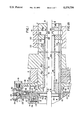
- FIG. 1 is a cross-sectional view of a first embodiment of the present invention
- FIG. 1a is a view of the first embodiment of FIG. 1 with a modified camshaft
- FIG. 2 is a cross-sectional view of a second embodiment of the present invention.
- FIG. 2a is a view of the second embodiment with a modified camshaft
- FIG. 3 is a schematic view of an oil circulating system of the arrangement of the present invention with a locking element shown in a first position;
- FIG. 4 is a schematic view of an oil circulating system of the arrangement of the present invention with a locking element shown in a second position;
- FIG. 5 is a view of the camshaft of a third embodiment of the present invention.
- FIG. 6 is a cross-sectional view of a cylinder head of an internal-combustion engine with the third embodiment of the present invention.
- FIG. 7 is a sectional view along Line VII--VII according to FIG. 6;
- FIG. 8 is a view from the direction of the arrow X according to FIG. 2.
- a phase converter 2 is assigned on the drive side end 3 to each of the two camshafts serving the intake.
- Each camshaft is held in several bearings 4 which are connected to a lubricating circulating system 5.
- the oil circulating system of the internal-combustion engine comprises the lubricating circulating system 5, an actuating circulating system for the adjustment of the phase converters 2 and a lubricating circulating system of a crankshaft 6 (FIG. 3) which is only schematically outlined.
- the phase converter 2 comprises three normally used elements which engage with one another by way of toothings. It comprises a wheel 8 which is constructed as a sprocket wheel 7 and serves for the drive of the camshaft 1. An interior hub 9, which carries a first helical toothing 11 constructed as the first external toothing 11, is welded into the wheel 8. By way of the first toothing 11, the wheel 8 is connected, by a corresponding first helical internal toothing 13, with a coupling member constructed as a piston 12 which is hydraulically acted upon on both sides. The coupling member is axially displaceable into two end positions E1, E2 with respect to the axis N extending longitudinally and centrically in the camshaft 1 (see FIGS. 3 and 4).
- the piston 12 carries a second helical external toothing 14 which engages in a corresponding toothing 16 which is constructed as the second internal toothing 16 of a hollow shaft 17 connected with a flange 18 of the camshaft 1.
- a cap 19 is pressed into the interior hub 9.
- the piston 12 divides a space 20 enclosed between the flange 18 and the hollow shaft 17 into a first chamber 21 and a second chamber 22.
- the piston 12 is in a first end position E1 which, during the operation of the internal-combustion engine, is taken up in a first operating condition, such as idling.
- the sprocket wheel 7 is axially fixed on the hollow shaft 17 by means of a prestressed spring ring 23.
- Half of the spring ring 23 is disposed in a groove 24 of the sprocket wheel 7 and the other half is disposed in a turned groove 25 of the hollow shaft 17, the depth of which is at least twice as large as that of the groove 24.
- the spring ring 23 is accessible by way of several assembly openings 26.
- sealing rings are inserted adjacent to the spring ring 23 and between the hollow shaft 17 and the flange 18.
- the spring ring 23 is placed in the turned groove 25 into which half of it dips because of its prestressing. Subsequently, the sprocket wheel 7 is pushed onto the hollow shaft 17 in which case a molded-on slope 27 presses the spring ring 23 completely into the turned groove 25 before, when the turned groove 25 and the groove 24 cover one another, half of it is placed in this groove 24.
- the cross-section of the spring ring 23 may be circular or rectangular.
- the sprocket wheel 7 is axially secured on the hollow shaft 17 by means of screws 28. These screws 28 are screwed into threads of the hollow shaft 17 and, by means of guide sleeves 29, are slidingly guided in oblong holes 30 of the sprocket wheel 7. In this case, a slight axial play A remains between the guide sleeve 29 and the wheel 8.
- the phase converter 2 is non-rotatably, by means of screwed connections 31, held in oblong holes 32 of the hollow shaft 17 by means of sleeve nuts 33.
- the oblong holes 32 permit a positionally correct mounting of the phase converter 2 irrespective of the position of the camshaft 1 which for the mounting is secured against turning.
- the phase converter 2 Before the mounting on the camshaft 1, the phase converter 2 can be completely preassembled. A pin is inserted into a fitted bore 34 (FIG. 8) penetrating the sprocket wheel and the hollow shaft 17 and secures both parts against twisting. Then, the sprocket wheel 7, as described above, is axially fixed on the hollow shaft 17 by means of a spring ring 23 or the screws 28 and the guide sleeves 29. After the pressing-in of the cap 19 and the sliding of the piston 12 into the toothings 11 and 16, the phase converter 2 is fastened to the flange 18 as a complete unit; in this case, the piston 12 is pushed onto a radial flange 35 of the camshaft 1.
- the oil circulating system of the internal-combustion engine has a pump 40 which delivers oil from a storage tank 41 through a filter 42. From there, a junction 43 leads to an on/off valve 44, to the crankshaft 6 of the internal-combustion engine and, by way of an oil-feeding duct 45, to a change-over valve 46 (or “locking element") arranged in parallel to this duct 45 as well as a pressure reducing valve 47 situated downstream.
- a pressure relief valve 48 is connected which limits the oil pressure delivered by the pump 40 to a maximum pressure PM.
- the lubricating circulating system 5 branches off from the pressure reducing valve 47 and admits a pressure P1 to the bearings which is preferably lower than the pressure PM.
- the change-over valve 46 has integrated check valves 49 by means of which the duct 45 can be coupled with the phase converters 2.
- a first and a second pipe 50 and 51 respectively lead from the change-over valve 46 to a separate bearing point 52 of the camshafts 1.
- ring ducts 53 extending in these bearing points 52, a connection takes place with first and second bores 54 and 55 extending radially in the camshafts 1.
- a cylindrical graduated recess 60 which extends from the end 3 rotationally symmetrically to the axis N, is provided in the camshaft 1 shown above the axis N. From the end 3 to directly behind the first bore 54, the recess 60 has a first diameter D1. Between the bores 54, 55, the recess 60 has a second smaller diameter D2, and from there to directly behind the second bore 55, a still smaller diameter D3. In the recess 60, a pipe 61 is held as a cylindrical body is radially widened at the end 3 to the diameter D1 and otherwise has the diameter D2.
- the pipe 61 therefore separates a ring-shaped exterior space 62 inside the recess 60 into which the first bore 54 leads and which, at the end 3, by way of an almost radially extending connecting bore 63, is connected with the first chamber 21.
- the second bore 55 intersects the recess 60 in the area of the diameter D3 and is connected with an interior space 64 extending inside the pipe 61.
- FIG. 1a a built-up hollow camshaft 1 is shown into which a bushing 65 is inserted.
- the pipe 61 is held in a clamping ring 66 as well as in the bushing 65.
- the flange 18 is constructed in one piece with the radial flange 35 and is pushed separately onto the camshaft 1.
- the second bore 55 extends partially in the bushing 65 and is, in turn, connected with the interior space 64.
- the exterior space 62 formed between the pipe 61 and the recess 60 connected the first bore 54 with the first chamber 21.
- FIG. 2a The modification shown in FIG. 2a, with respect to the bearing of the pipe 61 in the bushing 65, is identical with FIG. 1a, but the flange 18 is inserted into the built-up camshaft 1 in one piece with a sleeve 67.
- the pump 40 delivers oil from the storage tank 41 through the filter 42 to the junction 43.
- the on/off valve 44 is switched on or off by an electronic control unit 70 as a function of input signals of the load and rotational speed of the internal-combustion engine.
- the control unit 70 switches on the on/off switch 44 so that, from the direction of the junction 43, oil flows by way of the on/off valve 44, to the change-over valve 46 and shifts it into a second position S2 which corresponds to the end position E2 of the piston 12 (FIG. 4).
- the oil which by way of the check valves 49, flows into second annuli 72, will now, by way of the second pipes 51, reach the second bores 55. From there, the pressure acts, through the interior space 64, on the second chamber 22.
- the oil flows from the open end of the pipe 61, into a hollow space 73 formed by the radial flange 35 and the cap 19 and; from there, by way of openings 74 in the piston 12, into the second chamber 22.
- this piston 12 is axially displaced into the second end position E2, in which case, by way of the helical toothings 11, 13 and 14, 16, the sprocket wheel 7 is turned relative to the camshaft 1.
- rotational displacements occur in the phase converters 2 between the components bordering on sliding surfaces F.
- the oil volume which was displaced from the first chamber 21 during the shifting from the end position E1 into the end position E2, flows by way of the connecting bore 63, the exterior space 62 and the first bore 54, into the ring duct 53 and from there flows off by way of the first pipe 50.
- the annuli 71, 72 which receive oil flowing back from the phase converters 2, are connected with ascending pipes 75 which geodetically lead out above the phase converters 2 in the internal-combustion engine so that, after the switching-off of the internal-combustion engine, an emptying of the actuating circulating system is avoided.
- the pump 40 does not deliver a maximal pressure PM. If, in this case, a shifting of the piston 12 should nevertheless be necessary, the check valves 49 cause a gradual filling of the annuli 71, 72. As a result, the piston 12 is shifted from one end position into the other in a graduated manner.
- a duct 45, a change-over valve 46 with a check valve 49 as well as a pressure reducing valve 47 are assigned to each camshaft 1.
- no separate bearing point 52 is required in order to ensure the feeding and removal of oil in the camshaft 1.
- the radial first and second bores 54, 55 are arranged at points of the camshaft 1 that are supported in the bearings 4
- the bearings 4 are, in each case, constructed as an upper and a lower half 4a, 4b in a top part 80 and a bottom part 81 of a bearing frame 82 for camshafts (FIGS. 6 and 7).
- ducts 83, 84 extend as part of the lubricating circulating system 5. From the duct 83, which is situated downstream of the pressure reducing valve 47 and extends in parallel to the axis N in the top part 80, ducts 84 branch off rectangularly in a transverse plane Q to each bearing 4. Bores 85 receive screwed connections 86 for the fastening of the top part 80 on the bottom part 81.
- the ducts 84 are guided in a ring-shaped manner around the bores 85 situated between the axis N and the duct 83 so that the oil with the pressure P1 adjacent to the transverse plane Q, by way of two lubricating openings 87, supplies the bearing 4 in its upper half 4a.
- the supplying of the exterior space 62 and the interior space 64 takes place analogously to the first two embodiments of the invention, but the pipe 50 leading to the first bore 54 is arranged in a first bearing 4, and the pipe 51 leading to the second bore 55 is arranged in a second bearing which is adjacent to the first bearing 4.
- the lower halves 4b each have a groove 88 which according to FIG. 7 is arranged symmetrically with respect to the transverse plane Q between the lubricating openings 87.
- the first pipe 50 leads into this groove 88, and the second pipe 51 leads into the groove 88 of a second bearing 4.
- the bearing frame 82 is fastened to the side of a cylinder head 89 facing away from the combustion spaces in which some of the pipes 50, 51 of the actuating circulating system are arranged.
- the parts of the lubricating circulating system 5 and of the actuating circulating system, which are arranged in a bearing 4, and thus also the different oil pressures P1, PM are separated from one another.
- the camshaft 1 can be used in the modified form according to FIGS. 1a and 2a.
- the length of the bushing 65 is constructed corresponding to the distance between two adjacent bearings 4.
Landscapes
- Engineering & Computer Science (AREA)
- Mechanical Engineering (AREA)
- General Engineering & Computer Science (AREA)
- Valve Device For Special Equipments (AREA)
- Valve-Gear Or Valve Arrangements (AREA)
Applications Claiming Priority (2)
| Application Number | Priority Date | Filing Date | Title |
|---|---|---|---|
| DE4024056A DE4024056C1 (de) | 1990-07-28 | 1990-07-28 | |
| DE4024056 | 1990-07-28 |
Publications (1)
| Publication Number | Publication Date |
|---|---|
| US5170756A true US5170756A (en) | 1992-12-15 |
Family
ID=6411230
Family Applications (1)
| Application Number | Title | Priority Date | Filing Date |
|---|---|---|---|
| US07/735,005 Expired - Lifetime US5170756A (en) | 1990-07-28 | 1991-07-25 | Arrangement for changing the relative rotating position of shafts in an internal-combustion engine |
Country Status (4)
| Country | Link |
|---|---|
| US (1) | US5170756A (de) |
| EP (1) | EP0469334B2 (de) |
| JP (1) | JP3140093B2 (de) |
| DE (2) | DE4024056C1 (de) |
Cited By (10)
| Publication number | Priority date | Publication date | Assignee | Title |
|---|---|---|---|---|
| US5474038A (en) * | 1992-06-01 | 1995-12-12 | Ina Walzlager Schaeffler Kg | Device for continuous automatic angular adjustment between two shafts in driving relationship |
| US5483930A (en) * | 1993-05-19 | 1996-01-16 | Nippondenso Co., Ltd. | Valve timing control device |
| US5615648A (en) * | 1992-07-25 | 1997-04-01 | Robert Bosch Gmbh | Electro-hydraulic adjusting device |
| US5669343A (en) * | 1993-11-16 | 1997-09-23 | Nippondenso Co., Ltd. | Valve timing control system for internal combustion engine |
| EP0801211A1 (de) * | 1996-04-08 | 1997-10-15 | Toyota Jidosha Kabushiki Kaisha | Vorrichtung zum Verändern der Steuerzeiten einer Brennkraftmaschine |
| EP0816643A1 (de) * | 1996-07-03 | 1998-01-07 | Toyota Jidosha Kabushiki Kaisha | Hydraulischer Aktuator in einer Brennkraftmaschine |
| US5743155A (en) * | 1995-05-11 | 1998-04-28 | Carraro S. P. A. | Mechanical device for changing the phase relationship between the engine shaft and a camshaft of an internal combustion engine |
| US5799631A (en) * | 1996-10-15 | 1998-09-01 | Toyota Jidosha Kabushiki Kaisha | Apparatus for controlling engine valve performance |
| US20030213650A1 (en) * | 2002-03-26 | 2003-11-20 | Aisin Seiki Kabushiki Kaisha | Lubricant supply system for an engine |
| US9556765B2 (en) | 2012-11-20 | 2017-01-31 | Aisin Seiki Kabushiki Kaisha | Hydraulic oil supply apparatus |
Families Citing this family (11)
| Publication number | Priority date | Publication date | Assignee | Title |
|---|---|---|---|---|
| DE4023853A1 (de) * | 1990-07-27 | 1992-01-30 | Audi Ag | Ventilgesteuerte brennkraftmaschine |
| JPH04191406A (ja) * | 1990-11-26 | 1992-07-09 | Atsugi Unisia Corp | 内燃機関のバルブタイミング制御装置 |
| EP0582846B1 (de) * | 1992-08-13 | 1996-04-24 | Bayerische Motoren Werke Aktiengesellschaft | Hubkolben-Brennkraftmaschine mit zwei Gaswechselventilen je Zylinder |
| DE19620744B4 (de) * | 1995-06-07 | 2006-02-02 | Volkswagen Ag | Vorrichtung zur Beeinflussung der Steuerzeiten an einer Brennkraftmaschine |
| DE19529734A1 (de) * | 1995-08-12 | 1997-02-13 | Bayerische Motoren Werke Ag | Vorrichtung zur Drehwinkelverstellung einer Welle relativ zu einem Antriebsrad, insbesondere Steuerwelle einer Brennkraftmaschine |
| DE19813642A1 (de) * | 1998-03-27 | 1999-09-30 | Schaeffler Waelzlager Ohg | Vorrichtung zur Steuerung einer Brennkraftmaschine |
| DE10346446A1 (de) * | 2003-10-07 | 2005-05-12 | Daimler Chrysler Ag | Nockenwellenversteller für eine Brennkraftmaschine mit Hydraulikmittelführungen |
| DE102005026247A1 (de) * | 2005-06-08 | 2006-12-14 | Schaeffler Kg | Nockenwellentrieb für eine Brennkraftmaschine eines Kraftfahrzeugs |
| DE102006024793A1 (de) * | 2006-05-27 | 2007-11-29 | Mahle International Gmbh | Nockenwelle |
| GB2467943A (en) * | 2009-02-23 | 2010-08-25 | Mechadyne Plc | I.c. engine double overhead camshaft phasing system |
| DE102011012149A1 (de) * | 2011-02-24 | 2012-09-13 | GM Global Technology Operations LLC (n. d. Ges. d. Staates Delaware) | Zylinderkopf für eine Verbrennungskraftmaschine |
Citations (9)
| Publication number | Priority date | Publication date | Assignee | Title |
|---|---|---|---|---|
| DE361980C (de) * | 1922-10-20 | Krauss & Roeber | Drehbares, mit dem Antriebsrade kuppelbares Werkstueckfutter an Rundfraes- und Perlmaschinen | |
| US4787345A (en) * | 1986-05-14 | 1988-11-29 | Bayerische Motoren Werke A.G. | Arrangement for the relative angular position change of two shafts drivingly connected with each other, especially between a crankshaft supported in an engine housing of an internal combustion engine and a cam shaft |
| EP0335083A1 (de) * | 1988-03-30 | 1989-10-04 | Daimler-Benz Aktiengesellschaft | Vorrichtung zur relativen Winkelverstellung zwischen zwei in Antriebsverbindung stehenden Wellen |
| US4903650A (en) * | 1988-07-23 | 1990-02-27 | Daimler-Benz Ag | Apparatus for relative angular adjustment between two shafts in drive connection |
| EP0356162A1 (de) * | 1988-08-18 | 1990-02-28 | Atsugi Unisia Corporation | Zeitsteuervorrichtung |
| DE4029849A1 (de) * | 1989-09-20 | 1991-03-28 | Atsugi Unisia Corp | Ventilsteuerzeiten-einstellvorrichtung fuer brennkraftmaschine |
| US5012774A (en) * | 1989-03-04 | 1991-05-07 | Daimler-Benz Ag | Device for the relative angular adjustment of a camshaft |
| US5067450A (en) * | 1989-03-14 | 1991-11-26 | Aisin Seiki Kabushiki Kaisha | Variable valve timing system having rotational vibration damping |
| US5088456A (en) * | 1990-01-30 | 1992-02-18 | Atsugi-Unisia Corporation | Valve timing control system to adjust phase relationship between maximum, intermediate, and minimum advance position |
Family Cites Families (1)
| Publication number | Priority date | Publication date | Assignee | Title |
|---|---|---|---|---|
| US4996955A (en) * | 1988-09-30 | 1991-03-05 | Atsugi Unisia Corporation | Intake- and/or exhaust-valve timing control system for internal combustion engines |
-
1990
- 1990-07-28 DE DE4024056A patent/DE4024056C1/de not_active Expired - Lifetime
-
1991
- 1991-07-05 DE DE91111200T patent/DE59101147D1/de not_active Expired - Lifetime
- 1991-07-05 EP EP91111200A patent/EP0469334B2/de not_active Expired - Lifetime
- 1991-07-23 JP JP03182221A patent/JP3140093B2/ja not_active Expired - Lifetime
- 1991-07-25 US US07/735,005 patent/US5170756A/en not_active Expired - Lifetime
Patent Citations (11)
| Publication number | Priority date | Publication date | Assignee | Title |
|---|---|---|---|---|
| DE361980C (de) * | 1922-10-20 | Krauss & Roeber | Drehbares, mit dem Antriebsrade kuppelbares Werkstueckfutter an Rundfraes- und Perlmaschinen | |
| US4787345A (en) * | 1986-05-14 | 1988-11-29 | Bayerische Motoren Werke A.G. | Arrangement for the relative angular position change of two shafts drivingly connected with each other, especially between a crankshaft supported in an engine housing of an internal combustion engine and a cam shaft |
| EP0245791B1 (de) * | 1986-05-14 | 1990-10-31 | Bayerische Motoren Werke Aktiengesellschaft, Patentabteilung AJ-3 | Vorrichtung zur relativen Drehlagenänderung zweier in Antriebsverbindung stehender Wellen, insbesondere zwischen in einem Maschinengehäuse einer Brennkraftmaschine gelagerten Kurbelwelle und Nockenwelle |
| EP0335083A1 (de) * | 1988-03-30 | 1989-10-04 | Daimler-Benz Aktiengesellschaft | Vorrichtung zur relativen Winkelverstellung zwischen zwei in Antriebsverbindung stehenden Wellen |
| US4903650A (en) * | 1988-07-23 | 1990-02-27 | Daimler-Benz Ag | Apparatus for relative angular adjustment between two shafts in drive connection |
| EP0356162A1 (de) * | 1988-08-18 | 1990-02-28 | Atsugi Unisia Corporation | Zeitsteuervorrichtung |
| US5012774A (en) * | 1989-03-04 | 1991-05-07 | Daimler-Benz Ag | Device for the relative angular adjustment of a camshaft |
| US5067450A (en) * | 1989-03-14 | 1991-11-26 | Aisin Seiki Kabushiki Kaisha | Variable valve timing system having rotational vibration damping |
| DE4029849A1 (de) * | 1989-09-20 | 1991-03-28 | Atsugi Unisia Corp | Ventilsteuerzeiten-einstellvorrichtung fuer brennkraftmaschine |
| US5058539A (en) * | 1989-09-20 | 1991-10-22 | Atsugi Unisia Corporation | Valve timing adjusting system for internal combustion engine |
| US5088456A (en) * | 1990-01-30 | 1992-02-18 | Atsugi-Unisia Corporation | Valve timing control system to adjust phase relationship between maximum, intermediate, and minimum advance position |
Cited By (12)
| Publication number | Priority date | Publication date | Assignee | Title |
|---|---|---|---|---|
| US5474038A (en) * | 1992-06-01 | 1995-12-12 | Ina Walzlager Schaeffler Kg | Device for continuous automatic angular adjustment between two shafts in driving relationship |
| US5615648A (en) * | 1992-07-25 | 1997-04-01 | Robert Bosch Gmbh | Electro-hydraulic adjusting device |
| US5483930A (en) * | 1993-05-19 | 1996-01-16 | Nippondenso Co., Ltd. | Valve timing control device |
| US5669343A (en) * | 1993-11-16 | 1997-09-23 | Nippondenso Co., Ltd. | Valve timing control system for internal combustion engine |
| US5743155A (en) * | 1995-05-11 | 1998-04-28 | Carraro S. P. A. | Mechanical device for changing the phase relationship between the engine shaft and a camshaft of an internal combustion engine |
| EP0801211A1 (de) * | 1996-04-08 | 1997-10-15 | Toyota Jidosha Kabushiki Kaisha | Vorrichtung zum Verändern der Steuerzeiten einer Brennkraftmaschine |
| US5794579A (en) * | 1996-04-08 | 1998-08-18 | Toyota Jidosha Kabushiki Kaisha | Variable valve timing mechanism of engine |
| EP0816643A1 (de) * | 1996-07-03 | 1998-01-07 | Toyota Jidosha Kabushiki Kaisha | Hydraulischer Aktuator in einer Brennkraftmaschine |
| US5803031A (en) * | 1996-07-03 | 1998-09-08 | Toyota Jidosha Kabushiki Kaisha | Hydraulic actuator in an internal combustion engine |
| US5799631A (en) * | 1996-10-15 | 1998-09-01 | Toyota Jidosha Kabushiki Kaisha | Apparatus for controlling engine valve performance |
| US20030213650A1 (en) * | 2002-03-26 | 2003-11-20 | Aisin Seiki Kabushiki Kaisha | Lubricant supply system for an engine |
| US9556765B2 (en) | 2012-11-20 | 2017-01-31 | Aisin Seiki Kabushiki Kaisha | Hydraulic oil supply apparatus |
Also Published As
| Publication number | Publication date |
|---|---|
| EP0469334B2 (de) | 1997-04-09 |
| DE4024056C1 (de) | 1991-09-19 |
| JP3140093B2 (ja) | 2001-03-05 |
| EP0469334B1 (de) | 1994-03-09 |
| DE59101147D1 (de) | 1994-04-14 |
| JPH04232315A (ja) | 1992-08-20 |
| EP0469334A1 (de) | 1992-02-05 |
Similar Documents
| Publication | Publication Date | Title |
|---|---|---|
| US5138985A (en) | Arrangement for changing the valve timing of an internal-combustion engine | |
| US5170756A (en) | Arrangement for changing the relative rotating position of shafts in an internal-combustion engine | |
| US7025023B2 (en) | Hydraulic camshaft adjuster for an internal combustion engine | |
| US7681542B2 (en) | Camshaft adjustment device | |
| EP2787196B1 (de) | Verbrennungsmotor mit variabler verdichtung | |
| US5566651A (en) | Device for continuous angular adjustment between two shafts in driving relationship | |
| US4836156A (en) | Timing transmission device for an internal combustion engine | |
| US6186105B1 (en) | Variable valve timing arrangement for engine | |
| US6032629A (en) | Variable valve timing arrangement | |
| US7069951B2 (en) | Proportional solenoid valve for a camshaft adjusting device of motor vehicles | |
| US5014655A (en) | Camshaft drive of a multi-cylinder V-engine | |
| CA2128223C (en) | Variable timing gear device | |
| US4805566A (en) | Arrangement for influencing the control times of valves | |
| US5794578A (en) | Valve timing control apparatus | |
| US6164257A (en) | Oil passage construction for an engine with an oil pressure control device | |
| US5551389A (en) | Hydraulic pump driven by an internal combustion engine | |
| EP3070374B1 (de) | Schmierstruktur für ein kraftübertragungssystem | |
| EP0777037B2 (de) | Brennkraftmaschine mit einer Ventilzeitsteuerungsvorrichtung | |
| US20090084207A1 (en) | Split shaft for high power diesel engine | |
| EP0704605B1 (de) | Brennkraftmaschine mit Vorrichtung zur Verstellung der Nockenphase | |
| US6561153B2 (en) | Cylinder head spark plug mounting arrangement | |
| US6325031B1 (en) | Engine cam shaft drive incorporating VVT | |
| EP0362076B1 (de) | Ventilsteuervorrichtung für Brennkraftmaschine | |
| US4706626A (en) | Fuel injection pump for internal combustion engines | |
| JP4505984B2 (ja) | 内燃機関の動弁装置への給油構造 |
Legal Events
| Date | Code | Title | Description |
|---|---|---|---|
| AS | Assignment |
Owner name: DR. ING. H.C.F. PORSCHE AG, GERMANY Free format text: ASSIGNMENT OF ASSIGNORS INTEREST.;ASSIGNOR:SZODFRIDT, IMRE;REEL/FRAME:005860/0503 Effective date: 19910918 |
|
| STCF | Information on status: patent grant |
Free format text: PATENTED CASE |
|
| FPAY | Fee payment |
Year of fee payment: 4 |
|
| FPAY | Fee payment |
Year of fee payment: 8 |
|
| FPAY | Fee payment |
Year of fee payment: 12 |
|
| AS | Assignment |
Owner name: DR. ING. H.C.F. PORSCHE AKTIENGESELLSCHAFT (COMPAN Free format text: MERGER;ASSIGNOR:DR. ING. H.C.F. PORSCHE AKTIENGESELLSCHAFT (COMPANY NUMBER 5211);REEL/FRAME:021040/0147 Effective date: 20071113 |
|
| AS | Assignment |
Owner name: DR. ING. H.C.F. PORSCHE AKTIENGESELLSCHAFT, GERMAN Free format text: CHANGE OF NAME;ASSIGNOR:PORSCHE ZWISCHENHOLDING GMBH;REEL/FRAME:025227/0747 Effective date: 20091130 Owner name: PORSCHE ZWISCHENHOLDING GMBH, GERMANY Free format text: MERGER;ASSIGNOR:DR. ING. H.C.F. PORSCHE AKTIENGESELLSCHAFT;REEL/FRAME:025227/0699 Effective date: 20091125 |