US5169159A - Effective sealing device for engine flowpath - Google Patents
Effective sealing device for engine flowpath Download PDFInfo
- Publication number
- US5169159A US5169159A US07/767,959 US76795991A US5169159A US 5169159 A US5169159 A US 5169159A US 76795991 A US76795991 A US 76795991A US 5169159 A US5169159 A US 5169159A
- Authority
- US
- United States
- Prior art keywords
- seal
- face
- downstream
- ring seal
- upstream
- Prior art date
- Legal status (The legal status is an assumption and is not a legal conclusion. Google has not performed a legal analysis and makes no representation as to the accuracy of the status listed.)
- Expired - Fee Related
Links
Images


Classifications
-
- F—MECHANICAL ENGINEERING; LIGHTING; HEATING; WEAPONS; BLASTING
- F16—ENGINEERING ELEMENTS AND UNITS; GENERAL MEASURES FOR PRODUCING AND MAINTAINING EFFECTIVE FUNCTIONING OF MACHINES OR INSTALLATIONS; THERMAL INSULATION IN GENERAL
- F16J—PISTONS; CYLINDERS; SEALINGS
- F16J15/00—Sealings
- F16J15/44—Free-space packings
- F16J15/441—Free-space packings with floating ring
Definitions
- the present invention relates to sealing devices adjacent a gas flowpath of a gas turbine engine and, more particularly, to a ring seal having a seal dam on a high pressure side of the ring seal adjacent an outside diameter thereof.
- one object of the present invention is to provide a seal which maintains a low effective clearance level at sealing interfaces.
- Another object of the present invention is to provide a seal which is easy to assemble and install.
- Yet another object of the present invention is to provide a seal which is effective for long periods of use.
- a ring seal having an outside diameter seal dam which is positioned adjacent a high pressure side of the ring seal.
- This seal dam is aerodynamically connected to a low pressure side of the ring seal by a series of axial vents.
- a plurality of upstream face vents on the high pressure side are aerodynamically connected to a corresponding upstream transverse sealing dam.
- the upstream transverse face of the ring seal is subjected to an axial force F 1 originating from the high pressure fluid.
- a plurality of downstream face vents on the low pressure side are aerodynamically connected to a corresponding downstream transverse sealing dam.
- the upstream and downstream face vents serve to reduce an axial force exerted against the ring seal and the outside diameter vents serve to increase a radial force which pushes the ring seal against a stationary outer seat causing the ring seal to maintain a desired fixed position.
- the present invention is applicable to turbine engines used in military and commercial aircraft, and to marine and industrial engines.
- the outside diameter seal dam is perpendicularly connected to the upstream transverse face sealing dam at the high pressure side.
- the outside diameter sealing dam frictionally engages a stationary outer seat by being urged against the stationary outer seat by a radial force component (F3).
- the ring seal is further equipped with a downstream transverse face sealing dam which is perpendicularly connected to the outside diameter of the sealing ring.
- the downstream transverse face of the sealing ring is subjected to an axial pressure force F 2 which is opposite in direction to the axial pressure force F 1 .
- the upstream axial face of the ring seal is separated from a rotating gland by a first space, the upstream axial side including the upstream transverse face sealing dam.
- a downstream axial side of the ring seal is separated from the rotating gland by a second space, the downstream axial side of the ring seal including the downstream transverse face sealing dam 30.
- the ring seal has a radially inner surface which is separated from the rotating gland by a third space.
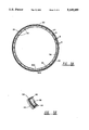
- FIG. 1 is a cross-sectional, schematic, radial side-view of a ring seal segment according to the present invention
- FIG. 2 is a perspective, partial cross-sectional illustration of a portion of a ring seal segment according to the present invention
- FIG. 3 is similar to FIG. 1 and includes force diagrams which portray the forces which act upon the ring seal of the present invention
- FIG. 4 is an axial schematic illustration of the upstream side of the ring seal of the present invention.
- FIG. 5A is an axial schematic illustration of the downstream side of the ring seal of the present invention.
- FIG. 5B is an enlarged perspective illustration of a portion of the ring seal of FIG. 5A;
- FIG. 6A is a closeup axial schematic illustration of the downstream side of the seal ring of the present invention.
- FIG. 6B is a cross-sectional illustration taken along line C--C of FIG. 6A which shows a tapered hydrodynamic air lifting pad according to one embodiment of the invention
- FIG. 6C is a cross-sectional illustration taken along line C--C of FIG. 6A which shows a stepped hydrodynamic air lifting pad according to another embodiment of the present invention and includes a graph showing where the maximum hydrodynamic pressure occurs;
- FIG. 7 is a closeup schematic illustration of the interlocking tab retention hooks of the present invention which connect two 180° segments which comprise the seal ring.
- a ring seal 10 according to the present invention is frictionally engaged with stationary outer seat 12 which is attached to an engine static frame or other non-rotating member (not shown).
- the ring seal 10 is located inside a rotating gland 14 which is affixed to a rotating structure (not shown) such as a shaft interconnecting turbine and compressor stages.
- An outside diameter (radially outer surface) seal dam 16 frictionally engages a radially inner bore or surface of the stationary outer seat 12 and forms, in combination with a transverse face sealing dam 18 located on the upstream high pressure (P 1 ) side of the ring seal 10, a corner portion of the ring seal 10.
- An upstream axial surface 20 of the ring seal 10, which includes the transverse face sealing dam 18, is separated from the rotating gland 14 by a first space 22 which has a width h 1 which typically measures approximately 0.001 inch.
- a radially inner surface or bore 24 of ring seal 10 is separated from the rotating gland 14 by a second space 26 which has a radial width of approximately 0.1 inch. Space 26 represents an area of intermediate pressure P 2 .
- a downstream axial surface 28 is separated from the rotating gland 14 on a low pressure P 3 side of the ring seal 10 by a third space 29 having a width h 2 which typically measures 0.001 inch, also.
- a bore vent 27 aerodynamically connects one side of the outside diameter seal dam 16 with the low pressure side of seal 10.
- the gland axial width is only slightly larger than the seal ring axial width.
- the variation in total transverse sealing face clearances at the seal/gland interfaces is very small, with (h 1 +h 2 ) being in the range of 0.0005 to 0.0025 inch.
- a part of the downstream or low pressure axial surface 28 has an interior surface 30I generally parallel to the axial surface 28 and defines the depth of downstream face vent 32 and downstream circumferential face groove or gap 34, as shown in FIG. 1.
- face vent 32 and face groove 34 may have slightly different depths as shown in FIG. 2.
- a shallow indentation in the downstream axial surface 28 is represented by hydrodynamic bearing lift pad 36 which abuts downstream face vent 32 and a circumferential groove 34.
- the upstream axial surface 20 has an interior edge 18I which lies generally parallel to the upstream axial surface 20 and defines the depth of an upstream face vent 38 and the depth of an upstream circumferential face groove 40.
- the outside diameter seal dam 16, the upstream transverse face sealing dam 18, and the downstream transverse face sealing dam 30 are in effect the three primary sealing dams which handle the pressure drops from the high pressure air side P 1 to the low pressure air side P 3 .
- the ring seal operates on principles similar to floating radial bushings, but operates in an axial direction.
- outside diameter seal dam 16 constitutes the outside radial extreme of the ring seal of the present invention.
- Bore vent 27 extends from transverse face 30 to circumferentially extending face groove 17 which defines the axially facing downstream wall of outside diameter seal dam 16.
- Hydrodynamic bearing lift pads 6 are located between downstream face vents 32, with vents 32 connecting to face grooves 34.
- FIG. 3 the principle forces and pressure profiles acting on the ring seal 10 are represented.
- P 1 represents the upstream high pressure
- P 2 is an intermediate pressure
- P 3 is the downstream low pressure
- F 1 and F 2 are axial forces
- F 3 and F 4 are radial forces.
- the high pressure P 1 pushes the ring seal toward the low pressure P 3 side.
- the high pressure P 1 causes a force F 3 to be exerted against the ring seal 10 so that the ring seal pushes against the outer stationary seat 12 where friction inhibits sliding motion.
- the seal tends to be self-centering.
- the rotating gland will push the seal toward the P 1 side at the highest arc point (if the gland is cocked or not perpendicular to the center axis of rotation). Also, the hydrodynamic air bearing lift pads 36 will discourage movement toward the P 3 side.
- FIG. 4 is an axial view of the upstream side of the ring seal of the present invention.
- the ring seal is comprised of two 180° segments 42 and 44 which are connected by complementary retention hooks 46A and 46B at each end of the respective segments.
- the ring seal 10 can be comprised of one contiguous piece having a singular gap similar to an automotive piston ring for radial expansion purposes. However, a segmented ring is preferred for purposes of overcoming overstress problems caused by expanding the ring over the gland outside diameter during assembly.
- Upstream face vents or slots 38 make a perpendicular connection with upstream circumferential face groove 40 with the upstream axial surface 20 being located between face vents 38 and radially inward from the upstream circumferential face groove 40.
- the face vents 38 are approximately 0.1 to 0.115 inches deep.
- the upstream transverse face sealing dam 18 is located radially outward of circumferential face groove 40.
- FIG. 5A an axial view of the downstream side of the ring seal is depicted.
- a plurality of hydrostatic bearing lift pads 36 are etched into the downstream axial surfaces 28 (twenty-eight pads are shown) with no pads being present where the segments 42 and 44 are joined by retention hooks 46A and 46B.
- a plurality of axial face vents or slots is located between the pads (thirty face vents are shown). The vents are approximately 0.100 to 0.115 inches deep.
- the seal has a uniform radial thickness of approximately 0.35 to 0.65 inches.
- vents are perpendicularly connected to downstream circumferential groove 34.
- the downstream transverse face sealing dam 30 extends circumferentially around the ring seal 10 and is located radially outward of circumferential face groove 34.
- a plurality of outside diameter vents 27 are located radially outward of downstream transverse face 30 and extend axially to circumferentially extending face groove 17 which defines the axially facing downstream wall of outside diameter seal dam 16.
- FIG. 6A hydrodynamic bearing lift pads 36 according to the present invention are etched into the downstream axial surface 28 of the ring seal such that one side of each lift pad connects to a face vent 32.
- Arrow 37 indicates the direction of gland surface rotation.
- FIG. 6B illustrates a tapered pad 36T according to one embodiment of the invention while
- FIG. 6C illustrates a stepped pad 36S according to another embodiment of the invention.
- FIGS. 6B and 6C are cross-sections taken along line C--C of FIG. 6A.
- the pressure profile graph of FIG. 6C applies to both the tapered and stepped pads and indicates that the maximum hydrodynamic pressure P max occurs in both the tapered and stepped pads at that side of the pads which do not make contact with a face vent 32.
- FIG. 7 depicts how the ends of each 180° segment of the ring seal are joined by tab retention hooks 46A and 46B.
- springs 48 push end gap 51 open until gap 50 is zero.
- Spring force in conjunction with the radially inward force component of angle locks the two segments to prevent disengaging from gland 14.
- Outside diameter seal dam 6 perpendicular to end gap 51 is larger than bore of radial seat 12 (see FIG. 1).
- ring outside diameter contracts to fit 12 and gap clearance 50 increases while 51 decreases.
- Circumferential clearance 50 and 51 are selected to accommodate the differential thermal expansion rates of the seal ring and outer seal materials.
- the preferred material is carbon graphite.
- a machinable mica glass ceramic (MACOR) or a high temperature (Meehanite) iron is preferably selected as the material for the seal ring.
- the ring seal 10 For the seal to properly function, the ring seal 10 must remain essentially stationary and seated against the outer stationary seat 12 where friction prevents continuous axial sliding and rubbing against the downstream face of the rotating gland 14.
- the relationship F a ⁇ F r *C f is required for all pressure levels.
- the ring seal 10 of the present invention has the outside diameter sealing dam 16 located on the upstream high pressure side.
- conventional state of the art seal dams are typically located on the downstream low pressure side.
- outside diameter vents 27 bleed the low pressure P 3 air to the downstream edge of the outside diameter sealing dams 16 which results in a substantial increase in the magnitude of radial pressure seating force F r .
- face vents 32 and 38 bleed the intermediate pressure P 2 to the interior edges 30I and 18I of the respective transverse face sealing dams 30 and 18 in order to significantly reduce the net axial pressure force F a .
- the surface of the radial seat 12 can be given a rough surface for the purpose of achieving a higher coefficient of friction.
- Hydrodynamic bearing lift pads 36 can be machined into the downstream axial surfaces 28 to create a stiff gas film which reduces or eliminates the ring-to-gland interface contact loads during axial translation, stator to rotor, where the translation is greater than the clearance.
- FIG. 6A several gas lift pads 36 (three are depicted) are separated in the circumferential direction by very deeply grooved face vents 32.
- the hydrodynamic rotation of the shaft forces air into spaces in the bearing lift pads 36.
- the hydrodynamic pressure rise is produced by the shearing gradient at the interface of the very shallow hydrodynamic bearing pockets and the surface of the rotating gland 14 which is connected to the rotating shaft.
- bearing configurations can be tapered-pad 36T (FIG. 6B) or stepped-pad 36S (FIG. 6C) depending upon the load and life requirements.
- the advantage of the ring seal of the present invention is that the effective leakage clearance areas at the sealing interfaces can be maintained at an extremely low level, i.e., approximately 0.002 inches or less, regardless of the seal diameter.
- a labyrinth seal operates with a radial clearance of 0.001 inches per inch of diameter.
- a labyrinth seal having a ten inch diameter would have a radial clearance of 0.010 inches.
- the present invention can significantly reduce fuel consumption and increase turbine blade life while generally improving overall efficiency/performance of the engine.
Landscapes
- Engineering & Computer Science (AREA)
- General Engineering & Computer Science (AREA)
- Mechanical Engineering (AREA)
- Turbine Rotor Nozzle Sealing (AREA)
- Sealing Using Fluids, Sealing Without Contact, And Removal Of Oil (AREA)
Priority Applications (4)
| Application Number | Priority Date | Filing Date | Title |
|---|---|---|---|
| US07/767,959 US5169159A (en) | 1991-09-30 | 1991-09-30 | Effective sealing device for engine flowpath |
| CA002076109A CA2076109A1 (en) | 1991-09-30 | 1992-08-13 | Effective sealing device for engine flowpath |
| EP92308653A EP0535850A1 (en) | 1991-09-30 | 1992-09-23 | Effective sealing device for engine flowpath |
| JP4259344A JPH0819860B2 (ja) | 1991-09-30 | 1992-09-29 | ガスタービンエンジン用リングシール |
Applications Claiming Priority (1)
| Application Number | Priority Date | Filing Date | Title |
|---|---|---|---|
| US07/767,959 US5169159A (en) | 1991-09-30 | 1991-09-30 | Effective sealing device for engine flowpath |
Publications (1)
| Publication Number | Publication Date |
|---|---|
| US5169159A true US5169159A (en) | 1992-12-08 |
Family
ID=25081093
Family Applications (1)
| Application Number | Title | Priority Date | Filing Date |
|---|---|---|---|
| US07/767,959 Expired - Fee Related US5169159A (en) | 1991-09-30 | 1991-09-30 | Effective sealing device for engine flowpath |
Country Status (4)
| Country | Link |
|---|---|
| US (1) | US5169159A (ja) |
| EP (1) | EP0535850A1 (ja) |
| JP (1) | JPH0819860B2 (ja) |
| CA (1) | CA2076109A1 (ja) |
Cited By (82)
| Publication number | Priority date | Publication date | Assignee | Title |
|---|---|---|---|---|
| US5301957A (en) * | 1992-04-27 | 1994-04-12 | General Electric Company | Expanding circumferential seal with upper-cooled runner |
| US5344162A (en) * | 1992-02-29 | 1994-09-06 | Rolls-Royce Plc | Sealing ring for gas turbine engines |
| US5368313A (en) * | 1993-03-03 | 1994-11-29 | A-C Compressor Corporation | Bushing for trapped bushing seal |
| WO1995006211A1 (en) * | 1992-02-26 | 1995-03-02 | Durametallic Corporation | Grooved face seal |
| WO1995006212A1 (en) * | 1993-08-26 | 1995-03-02 | Durametallic Corporation | Face seal with double groove arrangement |
| US5403019A (en) * | 1993-05-03 | 1995-04-04 | Dresser-Rand Company | Balanced floating labyrinth seal |
| US5445394A (en) * | 1992-03-04 | 1995-08-29 | Societe Nationale D'etude Et De Construction De Moteurs D'aviation (Snecma) | Sealing means between a pressurized chamber and a lubricated chamber |
| US5556111A (en) * | 1993-09-01 | 1996-09-17 | Durametallic Corporation | Face seal with angled grooves and shallow annular groove |
| US5558341A (en) * | 1995-01-11 | 1996-09-24 | Stein Seal Company | Seal for sealing an incompressible fluid between a relatively stationary seal and a movable member |
| US5695199A (en) * | 1994-03-14 | 1997-12-09 | Rao; V. Durga Nageswar | Piston sealing assembly |
| US5722665A (en) * | 1992-02-26 | 1998-03-03 | Durametallic Corporation | Spiral groove face seal |
| US5941532A (en) * | 1996-06-20 | 1999-08-24 | Rexnord Corporation | Aerospace housing and shaft assembly with noncontacting seal |
| US20040155410A1 (en) * | 2003-02-08 | 2004-08-12 | National Aeronautics And Space Administration | Noncontacting finger seal |
| US20060097457A1 (en) * | 2004-11-05 | 2006-05-11 | Flaherty Andrew L | Segmented shaft seal |
| US20080122183A1 (en) * | 2006-11-14 | 2008-05-29 | Braun Minel J | Double Padded Finger Seal |
| EP1988313A1 (en) * | 2007-05-01 | 2008-11-05 | EATON Corporation | Segmented seal portion and assembly |
| US20080284105A1 (en) * | 2006-06-21 | 2008-11-20 | Thurai Manik Vasagar | Low and reverse pressure application hydrodynamic pressurizing seals |
| US20090159724A1 (en) * | 2007-12-21 | 2009-06-25 | Kacik Mark S | Turbine valve |
| US20100164180A1 (en) * | 2008-12-31 | 2010-07-01 | Eaton Corporation | Hydrodynamic intershaft seal and assembly |
| US20100164183A1 (en) * | 2008-12-30 | 2010-07-01 | Eaton Corporation | Segmented seal with hydrodynamic feature and assembly |
| US20120223490A1 (en) * | 2011-03-02 | 2012-09-06 | Eaton Corporation | Segmented seal with axial load control feature |
| US20130272870A1 (en) * | 2012-04-17 | 2013-10-17 | General Electric Company | Mica-based seals for gas turbine shroud retaining clip |
| US8678754B2 (en) | 2011-01-24 | 2014-03-25 | General Electric Company | Assembly for preventing fluid flow |
| US20150016988A1 (en) * | 2013-07-08 | 2015-01-15 | Dresser-Rand Company | Seal for a high-pressure turbomachine |
| US20150167846A1 (en) * | 2013-12-18 | 2015-06-18 | George Perry Haynes | Bidirectional lift-off circumferential shaft seal segment and a shaft seal including a plurality of the segments |
| US20150247604A1 (en) * | 2014-03-03 | 2015-09-03 | Deere & Company | Splined shaft coupling arrangement |
| US9206742B2 (en) | 2012-12-29 | 2015-12-08 | United Technologies Corporation | Passages to facilitate a secondary flow between components |
| US20150361838A1 (en) * | 2012-04-04 | 2015-12-17 | Dimitrios Dardalis | Method and apparatus for rotating sleeve engine hydrodynamic seal |
| US9297312B2 (en) | 2012-12-29 | 2016-03-29 | United Technologies Corporation | Circumferentially retained fairing |
| US9347330B2 (en) | 2012-12-29 | 2016-05-24 | United Technologies Corporation | Finger seal |
| US9353635B2 (en) | 2011-08-16 | 2016-05-31 | General Electric Company | Seal end attachment |
| US9541006B2 (en) | 2012-12-29 | 2017-01-10 | United Technologies Corporation | Inter-module flow discourager |
| US9562478B2 (en) | 2012-12-29 | 2017-02-07 | United Technologies Corporation | Inter-module finger seal |
| US9631517B2 (en) | 2012-12-29 | 2017-04-25 | United Technologies Corporation | Multi-piece fairing for monolithic turbine exhaust case |
| US9638326B2 (en) | 2014-12-15 | 2017-05-02 | Kaydon Ring & Seal, Inc. | Arch-bound ring seal and ring seal system including an arch-bound ring seal |
| US9714712B2 (en) | 2014-08-15 | 2017-07-25 | Eaton Corporation | Hydrodynamic mating ring with integrated groove inlet pressure control |
| US9771818B2 (en) | 2012-12-29 | 2017-09-26 | United Technologies Corporation | Seals for a circumferential stop ring in a turbine exhaust case |
| US20170307085A1 (en) * | 2016-04-22 | 2017-10-26 | Kaydon Ring & Seal , Inc. | Circumferential shaft seal with radial displacement control |
| US9828867B2 (en) | 2012-12-29 | 2017-11-28 | United Technologies Corporation | Bumper for seals in a turbine exhaust case |
| US9845695B2 (en) | 2012-12-29 | 2017-12-19 | United Technologies Corporation | Gas turbine seal assembly and seal support |
| US9850780B2 (en) | 2012-12-29 | 2017-12-26 | United Technologies Corporation | Plate for directing flow and film cooling of components |
| US9850774B2 (en) | 2012-12-29 | 2017-12-26 | United Technologies Corporation | Flow diverter element and assembly |
| US9863261B2 (en) | 2012-12-29 | 2018-01-09 | United Technologies Corporation | Component retention with probe |
| US9890663B2 (en) | 2012-12-31 | 2018-02-13 | United Technologies Corporation | Turbine exhaust case multi-piece frame |
| US9903224B2 (en) | 2012-12-29 | 2018-02-27 | United Technologies Corporation | Scupper channelling in gas turbine modules |
| US9903216B2 (en) | 2012-12-29 | 2018-02-27 | United Technologies Corporation | Gas turbine seal assembly and seal support |
| US9927033B2 (en) | 2015-06-29 | 2018-03-27 | Kaydon Ring & Seal, Inc. | Split circumferential lift-off seal segment |
| US9982561B2 (en) | 2012-12-29 | 2018-05-29 | United Technologies Corporation | Heat shield for cooling a strut |
| US9982564B2 (en) | 2012-12-29 | 2018-05-29 | United Technologies Corporation | Turbine frame assembly and method of designing turbine frame assembly |
| US10006306B2 (en) | 2012-12-29 | 2018-06-26 | United Technologies Corporation | Turbine exhaust case architecture |
| US10041367B2 (en) | 2013-12-12 | 2018-08-07 | General Electric Company | Axially faced seal system |
| US10054009B2 (en) | 2012-12-31 | 2018-08-21 | United Technologies Corporation | Turbine exhaust case multi-piece frame |
| US10053998B2 (en) | 2012-12-29 | 2018-08-21 | United Technologies Corporation | Multi-purpose gas turbine seal support and assembly |
| US10060279B2 (en) | 2012-12-29 | 2018-08-28 | United Technologies Corporation | Seal support disk and assembly |
| US10087843B2 (en) | 2012-12-29 | 2018-10-02 | United Technologies Corporation | Mount with deflectable tabs |
| US10094389B2 (en) | 2012-12-29 | 2018-10-09 | United Technologies Corporation | Flow diverter to redirect secondary flow |
| US10138742B2 (en) | 2012-12-29 | 2018-11-27 | United Technologies Corporation | Multi-ply finger seal |
| US20190017605A1 (en) * | 2017-07-14 | 2019-01-17 | United Technologies Corporation | Ring seal arrangement with installation foolproofing |
| US10240481B2 (en) | 2012-12-29 | 2019-03-26 | United Technologies Corporation | Angled cut to direct radiative heat load |
| US10240532B2 (en) | 2012-12-29 | 2019-03-26 | United Technologies Corporation | Frame junction cooling holes |
| US10281045B2 (en) * | 2015-02-20 | 2019-05-07 | Rolls-Royce North American Technologies Inc. | Apparatus and methods for sealing components in gas turbine engines |
| WO2019091861A1 (de) * | 2017-11-09 | 2019-05-16 | Sms Group Gmbh | Dichtung gegen einen austritt von schmiermittel und walzgerüst mit der dichtung |
| US10294819B2 (en) | 2012-12-29 | 2019-05-21 | United Technologies Corporation | Multi-piece heat shield |
| US10329956B2 (en) | 2012-12-29 | 2019-06-25 | United Technologies Corporation | Multi-function boss for a turbine exhaust case |
| US10329957B2 (en) | 2012-12-31 | 2019-06-25 | United Technologies Corporation | Turbine exhaust case multi-piece framed |
| US10330011B2 (en) | 2013-03-11 | 2019-06-25 | United Technologies Corporation | Bench aft sub-assembly for turbine exhaust case fairing |
| US10337619B2 (en) | 2013-08-27 | 2019-07-02 | Eaton Intelligent Power Limited | Seal ring composite for improved hydrodynamic seal performance |
| US10364748B2 (en) | 2016-08-19 | 2019-07-30 | United Technologies Corporation | Finger seal flow metering |
| US10378370B2 (en) | 2012-12-29 | 2019-08-13 | United Technologies Corporation | Mechanical linkage for segmented heat shield |
| US10393272B2 (en) | 2015-11-24 | 2019-08-27 | Kaydon Ring & Seal, Inc. | Sleeve configured for use in a non-contacting gas seal and gas seal including the sleeve |
| US10408349B2 (en) * | 2015-03-16 | 2019-09-10 | Nok Corporation | Seal ring |
| US10472987B2 (en) | 2012-12-29 | 2019-11-12 | United Technologies Corporation | Heat shield for a casing |
| US10626741B2 (en) | 2015-01-21 | 2020-04-21 | United Technologies Corporation | Seal housing pre-taper |
| US11041396B2 (en) * | 2016-10-06 | 2021-06-22 | Raytheon Technologies Corporation | Axial-radial cooling slots on inner air seal |
| US11098604B2 (en) | 2016-10-06 | 2021-08-24 | Raytheon Technologies Corporation | Radial-axial cooling slots |
| US11125334B2 (en) | 2016-12-21 | 2021-09-21 | Eaton Intelligent Power Limited | Hydrodynamic sealing component and assembly |
| US11453090B2 (en) * | 2020-05-26 | 2022-09-27 | Raytheon Technologies Corporation | Piston seal assembly guards and inserts for seal groove |
| US11525515B2 (en) * | 2020-02-11 | 2022-12-13 | Raytheon Technologies Corporation | Radial seal segment joint |
| US11530749B2 (en) * | 2018-05-17 | 2022-12-20 | Eagle Industry Co., Ltd. | Seal ring |
| US11598426B2 (en) * | 2019-11-15 | 2023-03-07 | Kadant Johnson Llc | Rotary joint shroud having set-up gauge and seal wear indicator |
| US11644100B2 (en) | 2018-05-17 | 2023-05-09 | Eagle Industry Co., Ltd. | Seal ring |
| US20230323950A1 (en) * | 2022-04-06 | 2023-10-12 | Raytheon Technologies Corporation | Piston Seal Ring |
Families Citing this family (4)
| Publication number | Priority date | Publication date | Assignee | Title |
|---|---|---|---|---|
| US5370402A (en) * | 1993-05-07 | 1994-12-06 | Eg&G Sealol, Inc. | Pressure balanced compliant seal device |
| EP0629799A1 (en) * | 1993-06-15 | 1994-12-21 | EG&G SEALOL, INC. | Pressure balanced compliant seal device having a flexible annular member |
| DE19722998A1 (de) * | 1997-06-02 | 1998-12-10 | Gwj Engineering Gbr Dipl Ing G | Radiale Ringspaltdichtung |
| DE10062204A1 (de) * | 2000-12-13 | 2002-07-11 | Ksb Ag | Wellenabdichtung |
Citations (18)
| Publication number | Priority date | Publication date | Assignee | Title |
|---|---|---|---|---|
| US1999094A (en) * | 1933-10-31 | 1935-04-23 | William G G Godron | Sealing device, packing and the like |
| US3047299A (en) * | 1958-12-08 | 1962-07-31 | Asea Ab | Gland seals for gas-filled electric machines |
| GB920892A (en) * | 1961-01-17 | 1963-03-13 | Gen Electric Co Ltd | Improvements in or relating to seals for gas filled machines |
| US3305241A (en) * | 1965-10-19 | 1967-02-21 | Cooper Bessemer Corp | Packing ring structure |
| US3423070A (en) * | 1966-11-23 | 1969-01-21 | Gen Electric | Sealing means for turbomachinery |
| US3743303A (en) * | 1970-12-29 | 1973-07-03 | Gen Electric | Force balanced split ring dynamic shaft seals |
| US3791657A (en) * | 1972-04-27 | 1974-02-12 | Gen Electric | Dynamic lip seal |
| US3887198A (en) * | 1973-10-26 | 1975-06-03 | Caterpillar Tractor Co | Pressure balanced ring seal |
| US4082296A (en) * | 1976-05-26 | 1978-04-04 | Stein Philip C | Seal for sealing between a rotating member and a housing |
| US4218066A (en) * | 1976-03-23 | 1980-08-19 | United Technologies Corporation | Rotary seal |
| US4406466A (en) * | 1982-11-29 | 1983-09-27 | Elliott Turbomachinery Co., Inc. | Gas lift bearing and oil seal |
| US4504069A (en) * | 1982-04-23 | 1985-03-12 | Hep Products Ab | Sealing device between movable parts |
| US4513975A (en) * | 1984-04-27 | 1985-04-30 | General Electric Company | Thermally responsive labyrinth seal |
| US4552368A (en) * | 1983-12-01 | 1985-11-12 | Flexibox Limited | Backup seal with bush in form of radially floating washer |
| US4685684A (en) * | 1986-02-14 | 1987-08-11 | Ballard Michael J | Dynamic seal |
| US4832350A (en) * | 1987-12-21 | 1989-05-23 | Orlowski David C | One piece labyrinth seal |
| US4919439A (en) * | 1987-10-09 | 1990-04-24 | Williams International Corporation | Balanced ring seal |
| US5002288A (en) * | 1988-10-13 | 1991-03-26 | General Electric Company | Positive variable clearance labyrinth seal |
Family Cites Families (1)
| Publication number | Priority date | Publication date | Assignee | Title |
|---|---|---|---|---|
| US3365251A (en) * | 1966-04-28 | 1968-01-23 | Gen Electric | Seal assembly for antifriction bearings |
-
1991
- 1991-09-30 US US07/767,959 patent/US5169159A/en not_active Expired - Fee Related
-
1992
- 1992-08-13 CA CA002076109A patent/CA2076109A1/en not_active Abandoned
- 1992-09-23 EP EP92308653A patent/EP0535850A1/en not_active Withdrawn
- 1992-09-29 JP JP4259344A patent/JPH0819860B2/ja not_active Ceased
Patent Citations (18)
| Publication number | Priority date | Publication date | Assignee | Title |
|---|---|---|---|---|
| US1999094A (en) * | 1933-10-31 | 1935-04-23 | William G G Godron | Sealing device, packing and the like |
| US3047299A (en) * | 1958-12-08 | 1962-07-31 | Asea Ab | Gland seals for gas-filled electric machines |
| GB920892A (en) * | 1961-01-17 | 1963-03-13 | Gen Electric Co Ltd | Improvements in or relating to seals for gas filled machines |
| US3305241A (en) * | 1965-10-19 | 1967-02-21 | Cooper Bessemer Corp | Packing ring structure |
| US3423070A (en) * | 1966-11-23 | 1969-01-21 | Gen Electric | Sealing means for turbomachinery |
| US3743303A (en) * | 1970-12-29 | 1973-07-03 | Gen Electric | Force balanced split ring dynamic shaft seals |
| US3791657A (en) * | 1972-04-27 | 1974-02-12 | Gen Electric | Dynamic lip seal |
| US3887198A (en) * | 1973-10-26 | 1975-06-03 | Caterpillar Tractor Co | Pressure balanced ring seal |
| US4218066A (en) * | 1976-03-23 | 1980-08-19 | United Technologies Corporation | Rotary seal |
| US4082296A (en) * | 1976-05-26 | 1978-04-04 | Stein Philip C | Seal for sealing between a rotating member and a housing |
| US4504069A (en) * | 1982-04-23 | 1985-03-12 | Hep Products Ab | Sealing device between movable parts |
| US4406466A (en) * | 1982-11-29 | 1983-09-27 | Elliott Turbomachinery Co., Inc. | Gas lift bearing and oil seal |
| US4552368A (en) * | 1983-12-01 | 1985-11-12 | Flexibox Limited | Backup seal with bush in form of radially floating washer |
| US4513975A (en) * | 1984-04-27 | 1985-04-30 | General Electric Company | Thermally responsive labyrinth seal |
| US4685684A (en) * | 1986-02-14 | 1987-08-11 | Ballard Michael J | Dynamic seal |
| US4919439A (en) * | 1987-10-09 | 1990-04-24 | Williams International Corporation | Balanced ring seal |
| US4832350A (en) * | 1987-12-21 | 1989-05-23 | Orlowski David C | One piece labyrinth seal |
| US5002288A (en) * | 1988-10-13 | 1991-03-26 | General Electric Company | Positive variable clearance labyrinth seal |
Cited By (116)
| Publication number | Priority date | Publication date | Assignee | Title |
|---|---|---|---|---|
| WO1995006211A1 (en) * | 1992-02-26 | 1995-03-02 | Durametallic Corporation | Grooved face seal |
| US5722665A (en) * | 1992-02-26 | 1998-03-03 | Durametallic Corporation | Spiral groove face seal |
| US5344162A (en) * | 1992-02-29 | 1994-09-06 | Rolls-Royce Plc | Sealing ring for gas turbine engines |
| US5445394A (en) * | 1992-03-04 | 1995-08-29 | Societe Nationale D'etude Et De Construction De Moteurs D'aviation (Snecma) | Sealing means between a pressurized chamber and a lubricated chamber |
| US5301957A (en) * | 1992-04-27 | 1994-04-12 | General Electric Company | Expanding circumferential seal with upper-cooled runner |
| US5368313A (en) * | 1993-03-03 | 1994-11-29 | A-C Compressor Corporation | Bushing for trapped bushing seal |
| US5403019A (en) * | 1993-05-03 | 1995-04-04 | Dresser-Rand Company | Balanced floating labyrinth seal |
| WO1995006212A1 (en) * | 1993-08-26 | 1995-03-02 | Durametallic Corporation | Face seal with double groove arrangement |
| US5556111A (en) * | 1993-09-01 | 1996-09-17 | Durametallic Corporation | Face seal with angled grooves and shallow annular groove |
| US5695199A (en) * | 1994-03-14 | 1997-12-09 | Rao; V. Durga Nageswar | Piston sealing assembly |
| US5558341A (en) * | 1995-01-11 | 1996-09-24 | Stein Seal Company | Seal for sealing an incompressible fluid between a relatively stationary seal and a movable member |
| US5941532A (en) * | 1996-06-20 | 1999-08-24 | Rexnord Corporation | Aerospace housing and shaft assembly with noncontacting seal |
| US6257589B1 (en) | 1996-06-20 | 2001-07-10 | Rexnord Corporation | Aerospace housing and shaft assembly |
| US6811154B2 (en) | 2003-02-08 | 2004-11-02 | The United States Of America As Represented By The Administrator Of The National Aeronautics And Space Administration | Noncontacting finger seal |
| US20040155410A1 (en) * | 2003-02-08 | 2004-08-12 | National Aeronautics And Space Administration | Noncontacting finger seal |
| US7540501B2 (en) * | 2004-11-05 | 2009-06-02 | Flowserve Management Company | Segmented shaft seal |
| US20060097457A1 (en) * | 2004-11-05 | 2006-05-11 | Flaherty Andrew L | Segmented shaft seal |
| US8616554B2 (en) * | 2006-06-21 | 2013-12-31 | Stein Seal Company | Low and reverse pressure application hydrodynamic pressurizing seals |
| US20130113162A1 (en) * | 2006-06-21 | 2013-05-09 | Stein Seal Company | Low and Reverse Pressure Application Hydrodynamic Pressurizing Seals |
| US20080284105A1 (en) * | 2006-06-21 | 2008-11-20 | Thurai Manik Vasagar | Low and reverse pressure application hydrodynamic pressurizing seals |
| US20110115164A1 (en) * | 2006-06-21 | 2011-05-19 | Stein Seal Company | Low and Reverse Pressure Application Hydrodynamic Pressurizing Seals |
| US8408556B2 (en) * | 2006-06-21 | 2013-04-02 | Stein Seal Company | Low and reverse pressure application hydrodynamic pressurizing seals |
| US8356819B2 (en) * | 2006-06-21 | 2013-01-22 | Stein Seal Company | Low and reverse pressure application hydrodynamic pressurizing seals |
| US8342534B2 (en) * | 2006-06-21 | 2013-01-01 | Stein Seal Company | Low and reverse pressure application hydrodynamic pressurizing seals |
| US8074995B2 (en) * | 2006-06-21 | 2011-12-13 | Stein Seal Company | Low and reverse pressure application hydrodynamic pressurizing seals |
| US20110215535A1 (en) * | 2006-06-21 | 2011-09-08 | Stein Seal Company | Low and Reverse Pressure Application Hydrodynamic Pressurizing Seals |
| US20110210518A1 (en) * | 2006-06-21 | 2011-09-01 | Stein Seal Company | Low and Reverse Pressure Application Hydrodynamic Pressurizing Seals |
| US20110210514A1 (en) * | 2006-06-21 | 2011-09-01 | Stein Seal Company | Low and Reverse Pressure Application Hydrodynamic Pressurizing Seals |
| US7735833B2 (en) | 2006-11-14 | 2010-06-15 | The University Of Akron | Double padded finger seal |
| US20080122183A1 (en) * | 2006-11-14 | 2008-05-29 | Braun Minel J | Double Padded Finger Seal |
| US7770895B2 (en) | 2007-05-01 | 2010-08-10 | Eaton Corporation | Segmented seal portion and assembly |
| EP1988313A1 (en) * | 2007-05-01 | 2008-11-05 | EATON Corporation | Segmented seal portion and assembly |
| US20080272552A1 (en) * | 2007-05-01 | 2008-11-06 | Eaton Corporation | Segmented seal portion and assembly |
| US20090159724A1 (en) * | 2007-12-21 | 2009-06-25 | Kacik Mark S | Turbine valve |
| US20100164183A1 (en) * | 2008-12-30 | 2010-07-01 | Eaton Corporation | Segmented seal with hydrodynamic feature and assembly |
| US7914007B2 (en) * | 2008-12-30 | 2011-03-29 | Eaton Corporation | Segmented seal with hydrodynamic feature and assembly |
| US8100403B2 (en) | 2008-12-31 | 2012-01-24 | Eaton Corporation | Hydrodynamic intershaft seal and assembly |
| US20100164180A1 (en) * | 2008-12-31 | 2010-07-01 | Eaton Corporation | Hydrodynamic intershaft seal and assembly |
| WO2010076641A1 (en) * | 2008-12-31 | 2010-07-08 | Eaton Corporation | Hydrodynamic intershaft seal and assembly |
| US8678754B2 (en) | 2011-01-24 | 2014-03-25 | General Electric Company | Assembly for preventing fluid flow |
| US20120223490A1 (en) * | 2011-03-02 | 2012-09-06 | Eaton Corporation | Segmented seal with axial load control feature |
| US8905407B2 (en) * | 2011-03-02 | 2014-12-09 | Eaton Corporation | Segmented seal with axial load control feature |
| US9353635B2 (en) | 2011-08-16 | 2016-05-31 | General Electric Company | Seal end attachment |
| US20150361838A1 (en) * | 2012-04-04 | 2015-12-17 | Dimitrios Dardalis | Method and apparatus for rotating sleeve engine hydrodynamic seal |
| US10563509B2 (en) * | 2012-04-04 | 2020-02-18 | Dimitrios Dardalis | Method and apparatus for rotating sleeve engine hydrodynamic seal |
| US20130272870A1 (en) * | 2012-04-17 | 2013-10-17 | General Electric Company | Mica-based seals for gas turbine shroud retaining clip |
| US10329956B2 (en) | 2012-12-29 | 2019-06-25 | United Technologies Corporation | Multi-function boss for a turbine exhaust case |
| US10240532B2 (en) | 2012-12-29 | 2019-03-26 | United Technologies Corporation | Frame junction cooling holes |
| US10941674B2 (en) | 2012-12-29 | 2021-03-09 | Raytheon Technologies Corporation | Multi-piece heat shield |
| US9297312B2 (en) | 2012-12-29 | 2016-03-29 | United Technologies Corporation | Circumferentially retained fairing |
| US10472987B2 (en) | 2012-12-29 | 2019-11-12 | United Technologies Corporation | Heat shield for a casing |
| US9347330B2 (en) | 2012-12-29 | 2016-05-24 | United Technologies Corporation | Finger seal |
| US10378370B2 (en) | 2012-12-29 | 2019-08-13 | United Technologies Corporation | Mechanical linkage for segmented heat shield |
| US9541006B2 (en) | 2012-12-29 | 2017-01-10 | United Technologies Corporation | Inter-module flow discourager |
| US9562478B2 (en) | 2012-12-29 | 2017-02-07 | United Technologies Corporation | Inter-module finger seal |
| US9631517B2 (en) | 2012-12-29 | 2017-04-25 | United Technologies Corporation | Multi-piece fairing for monolithic turbine exhaust case |
| US10294819B2 (en) | 2012-12-29 | 2019-05-21 | United Technologies Corporation | Multi-piece heat shield |
| US9206742B2 (en) | 2012-12-29 | 2015-12-08 | United Technologies Corporation | Passages to facilitate a secondary flow between components |
| US10240481B2 (en) | 2012-12-29 | 2019-03-26 | United Technologies Corporation | Angled cut to direct radiative heat load |
| US9771818B2 (en) | 2012-12-29 | 2017-09-26 | United Technologies Corporation | Seals for a circumferential stop ring in a turbine exhaust case |
| US10138742B2 (en) | 2012-12-29 | 2018-11-27 | United Technologies Corporation | Multi-ply finger seal |
| US9828867B2 (en) | 2012-12-29 | 2017-11-28 | United Technologies Corporation | Bumper for seals in a turbine exhaust case |
| US9845695B2 (en) | 2012-12-29 | 2017-12-19 | United Technologies Corporation | Gas turbine seal assembly and seal support |
| US9850780B2 (en) | 2012-12-29 | 2017-12-26 | United Technologies Corporation | Plate for directing flow and film cooling of components |
| US9850774B2 (en) | 2012-12-29 | 2017-12-26 | United Technologies Corporation | Flow diverter element and assembly |
| US9863261B2 (en) | 2012-12-29 | 2018-01-09 | United Technologies Corporation | Component retention with probe |
| US10094389B2 (en) | 2012-12-29 | 2018-10-09 | United Technologies Corporation | Flow diverter to redirect secondary flow |
| US9903224B2 (en) | 2012-12-29 | 2018-02-27 | United Technologies Corporation | Scupper channelling in gas turbine modules |
| US9903216B2 (en) | 2012-12-29 | 2018-02-27 | United Technologies Corporation | Gas turbine seal assembly and seal support |
| US10087843B2 (en) | 2012-12-29 | 2018-10-02 | United Technologies Corporation | Mount with deflectable tabs |
| US9982561B2 (en) | 2012-12-29 | 2018-05-29 | United Technologies Corporation | Heat shield for cooling a strut |
| US9982564B2 (en) | 2012-12-29 | 2018-05-29 | United Technologies Corporation | Turbine frame assembly and method of designing turbine frame assembly |
| US10006306B2 (en) | 2012-12-29 | 2018-06-26 | United Technologies Corporation | Turbine exhaust case architecture |
| US10060279B2 (en) | 2012-12-29 | 2018-08-28 | United Technologies Corporation | Seal support disk and assembly |
| US10053998B2 (en) | 2012-12-29 | 2018-08-21 | United Technologies Corporation | Multi-purpose gas turbine seal support and assembly |
| US9890663B2 (en) | 2012-12-31 | 2018-02-13 | United Technologies Corporation | Turbine exhaust case multi-piece frame |
| US10054009B2 (en) | 2012-12-31 | 2018-08-21 | United Technologies Corporation | Turbine exhaust case multi-piece frame |
| US10329957B2 (en) | 2012-12-31 | 2019-06-25 | United Technologies Corporation | Turbine exhaust case multi-piece framed |
| US10330011B2 (en) | 2013-03-11 | 2019-06-25 | United Technologies Corporation | Bench aft sub-assembly for turbine exhaust case fairing |
| US20150016988A1 (en) * | 2013-07-08 | 2015-01-15 | Dresser-Rand Company | Seal for a high-pressure turbomachine |
| US9303655B2 (en) * | 2013-07-08 | 2016-04-05 | Dresser-Rand Company | Seal for a high-pressure turbomachine |
| US10337619B2 (en) | 2013-08-27 | 2019-07-02 | Eaton Intelligent Power Limited | Seal ring composite for improved hydrodynamic seal performance |
| US10041367B2 (en) | 2013-12-12 | 2018-08-07 | General Electric Company | Axially faced seal system |
| US9695940B2 (en) * | 2013-12-18 | 2017-07-04 | Kaydon Ring & Seal, Inc. | Bidirectional lift-off circumferential shaft seal segment and a shaft seal including a plurality of the segments |
| US20150167846A1 (en) * | 2013-12-18 | 2015-06-18 | George Perry Haynes | Bidirectional lift-off circumferential shaft seal segment and a shaft seal including a plurality of the segments |
| CN104895941A (zh) * | 2014-03-03 | 2015-09-09 | 迪尔公司 | 花键轴联接装置 |
| US20150247604A1 (en) * | 2014-03-03 | 2015-09-03 | Deere & Company | Splined shaft coupling arrangement |
| CN104895941B (zh) * | 2014-03-03 | 2019-04-26 | 迪尔公司 | 花键轴联接装置 |
| US9714712B2 (en) | 2014-08-15 | 2017-07-25 | Eaton Corporation | Hydrodynamic mating ring with integrated groove inlet pressure control |
| US9638326B2 (en) | 2014-12-15 | 2017-05-02 | Kaydon Ring & Seal, Inc. | Arch-bound ring seal and ring seal system including an arch-bound ring seal |
| US10626741B2 (en) | 2015-01-21 | 2020-04-21 | United Technologies Corporation | Seal housing pre-taper |
| US10281045B2 (en) * | 2015-02-20 | 2019-05-07 | Rolls-Royce North American Technologies Inc. | Apparatus and methods for sealing components in gas turbine engines |
| US10408349B2 (en) * | 2015-03-16 | 2019-09-10 | Nok Corporation | Seal ring |
| US9927033B2 (en) | 2015-06-29 | 2018-03-27 | Kaydon Ring & Seal, Inc. | Split circumferential lift-off seal segment |
| US10393272B2 (en) | 2015-11-24 | 2019-08-27 | Kaydon Ring & Seal, Inc. | Sleeve configured for use in a non-contacting gas seal and gas seal including the sleeve |
| US20170307085A1 (en) * | 2016-04-22 | 2017-10-26 | Kaydon Ring & Seal , Inc. | Circumferential shaft seal with radial displacement control |
| US10364748B2 (en) | 2016-08-19 | 2019-07-30 | United Technologies Corporation | Finger seal flow metering |
| US11098604B2 (en) | 2016-10-06 | 2021-08-24 | Raytheon Technologies Corporation | Radial-axial cooling slots |
| US11041396B2 (en) * | 2016-10-06 | 2021-06-22 | Raytheon Technologies Corporation | Axial-radial cooling slots on inner air seal |
| US11125334B2 (en) | 2016-12-21 | 2021-09-21 | Eaton Intelligent Power Limited | Hydrodynamic sealing component and assembly |
| US10619742B2 (en) * | 2017-07-14 | 2020-04-14 | United Technologies Corporation | Ring seal arrangement with installation foolproofing |
| US20190017605A1 (en) * | 2017-07-14 | 2019-01-17 | United Technologies Corporation | Ring seal arrangement with installation foolproofing |
| US11717869B2 (en) * | 2017-11-09 | 2023-08-08 | Sms Group Gmbh | Seal to prevent lubricant escaping, and rolling stand having said seal |
| TWI699246B (zh) * | 2017-11-09 | 2020-07-21 | 德商Sms集團有限公司 | 防止潤滑劑洩露的密封件以及具有此密封件的滾軋機機架 |
| WO2019091861A1 (de) * | 2017-11-09 | 2019-05-16 | Sms Group Gmbh | Dichtung gegen einen austritt von schmiermittel und walzgerüst mit der dichtung |
| CN111432949A (zh) * | 2017-11-09 | 2020-07-17 | Sms集团有限公司 | 防止润滑剂泄漏的密封件和具有该密封件的轧机机架 |
| CN111432949B (zh) * | 2017-11-09 | 2022-04-08 | Sms集团有限公司 | 具有防止润滑剂泄漏的密封件的轧机机架 |
| US20210170461A1 (en) * | 2017-11-09 | 2021-06-10 | Sms Group Gmbh | Seal to prevent lubricant escaping, and rolling stand having said seal |
| US11530749B2 (en) * | 2018-05-17 | 2022-12-20 | Eagle Industry Co., Ltd. | Seal ring |
| US11644100B2 (en) | 2018-05-17 | 2023-05-09 | Eagle Industry Co., Ltd. | Seal ring |
| US11598426B2 (en) * | 2019-11-15 | 2023-03-07 | Kadant Johnson Llc | Rotary joint shroud having set-up gauge and seal wear indicator |
| US11525515B2 (en) * | 2020-02-11 | 2022-12-13 | Raytheon Technologies Corporation | Radial seal segment joint |
| US11453090B2 (en) * | 2020-05-26 | 2022-09-27 | Raytheon Technologies Corporation | Piston seal assembly guards and inserts for seal groove |
| US11945063B2 (en) | 2020-05-26 | 2024-04-02 | Rtx Corporation | Piston seal assembly guards and inserts for seal groove |
| US20230323950A1 (en) * | 2022-04-06 | 2023-10-12 | Raytheon Technologies Corporation | Piston Seal Ring |
| US11892083B2 (en) * | 2022-04-06 | 2024-02-06 | Rtx Corporation | Piston seal ring |
Also Published As
| Publication number | Publication date |
|---|---|
| JPH0819860B2 (ja) | 1996-02-28 |
| EP0535850A1 (en) | 1993-04-07 |
| CA2076109A1 (en) | 1993-03-31 |
| JPH05195816A (ja) | 1993-08-03 |
Similar Documents
| Publication | Publication Date | Title |
|---|---|---|
| US5169159A (en) | Effective sealing device for engine flowpath | |
| KR100266251B1 (ko) | 기계적 표면 밀봉수단 | |
| EP0629798B1 (en) | Pressure balanced compliant seal device | |
| US6145843A (en) | Hydrodynamic lift seal for use with compressible fluids | |
| US5755445A (en) | Noncontacting finger seal with hydrodynamic foot portion | |
| US5145189A (en) | Hydro-lift dynamic circumferential seal | |
| US7320468B2 (en) | Sealing arrangement | |
| EP0595437B1 (en) | Mechanical face seals | |
| EP2376822B1 (en) | Segmented seal with hydrodynamic feature and assembly | |
| EP1299663B1 (en) | Rotary face seal assembly | |
| CA1154687A (en) | Axially flexible radially stiff retaining ring for sealing in a gas turbine engine | |
| US6244599B1 (en) | Floating brush seal | |
| WO1998008010A9 (en) | Noncontacting finger seal | |
| JPH0599345A (ja) | 改良型らせん溝ガス潤滑式シール | |
| EP0803668B1 (en) | Seal for sealing an incompressible fluid between a relatively stationary seal and a movable member | |
| US5531458A (en) | Face seal with angled grooves | |
| WO2002093046A1 (en) | Mechanical seal | |
| US5006043A (en) | Floating annular seal with thermal compensation | |
| GB2134604A (en) | Rotatable shaft seals | |
| GB2300028A (en) | A shaft seal | |
| EP0629799A1 (en) | Pressure balanced compliant seal device having a flexible annular member | |
| US4260166A (en) | Self-stabilizing radial face seal | |
| JPH1047494A (ja) | 高圧用メカニカルシール |
Legal Events
| Date | Code | Title | Description |
|---|---|---|---|
| AS | Assignment |
Owner name: GENERAL ELECTRIC COMPANY Free format text: ASSIGNMENT OF ASSIGNORS INTEREST.;ASSIGNORS:POPE, ADAM N.;HWANG, MING-FONG;REEL/FRAME:005871/0905 Effective date: 19910919 |
|
| REMI | Maintenance fee reminder mailed | ||
| LAPS | Lapse for failure to pay maintenance fees | ||
| FP | Expired due to failure to pay maintenance fee |
Effective date: 19961211 |
|
| STCH | Information on status: patent discontinuation |
Free format text: PATENT EXPIRED DUE TO NONPAYMENT OF MAINTENANCE FEES UNDER 37 CFR 1.362 |