US5127809A - Scroll compressor with reinforcing ribs on the orbiting scroll - Google Patents
Scroll compressor with reinforcing ribs on the orbiting scroll Download PDFInfo
- Publication number
- US5127809A US5127809A US07/639,333 US63933391A US5127809A US 5127809 A US5127809 A US 5127809A US 63933391 A US63933391 A US 63933391A US 5127809 A US5127809 A US 5127809A
- Authority
- US
- United States
- Prior art keywords
- orbiting scroll
- end plate
- scroll
- orbiting
- frame
- Prior art date
- Legal status (The legal status is an assumption and is not a legal conclusion. Google has not performed a legal analysis and makes no representation as to the accuracy of the status listed.)
- Expired - Lifetime
Links
Images


Classifications
-
- F—MECHANICAL ENGINEERING; LIGHTING; HEATING; WEAPONS; BLASTING
- F04—POSITIVE - DISPLACEMENT MACHINES FOR LIQUIDS; PUMPS FOR LIQUIDS OR ELASTIC FLUIDS
- F04C—ROTARY-PISTON, OR OSCILLATING-PISTON, POSITIVE-DISPLACEMENT MACHINES FOR LIQUIDS; ROTARY-PISTON, OR OSCILLATING-PISTON, POSITIVE-DISPLACEMENT PUMPS
- F04C18/00—Rotary-piston pumps specially adapted for elastic fluids
- F04C18/02—Rotary-piston pumps specially adapted for elastic fluids of arcuate-engagement type, i.e. with circular translatory movement of co-operating members, each member having the same number of teeth or tooth-equivalents
- F04C18/0207—Rotary-piston pumps specially adapted for elastic fluids of arcuate-engagement type, i.e. with circular translatory movement of co-operating members, each member having the same number of teeth or tooth-equivalents both members having co-operating elements in spiral form
- F04C18/0215—Rotary-piston pumps specially adapted for elastic fluids of arcuate-engagement type, i.e. with circular translatory movement of co-operating members, each member having the same number of teeth or tooth-equivalents both members having co-operating elements in spiral form where only one member is moving
-
- F—MECHANICAL ENGINEERING; LIGHTING; HEATING; WEAPONS; BLASTING
- F04—POSITIVE - DISPLACEMENT MACHINES FOR LIQUIDS; PUMPS FOR LIQUIDS OR ELASTIC FLUIDS
- F04C—ROTARY-PISTON, OR OSCILLATING-PISTON, POSITIVE-DISPLACEMENT MACHINES FOR LIQUIDS; ROTARY-PISTON, OR OSCILLATING-PISTON, POSITIVE-DISPLACEMENT PUMPS
- F04C18/00—Rotary-piston pumps specially adapted for elastic fluids
- F04C18/02—Rotary-piston pumps specially adapted for elastic fluids of arcuate-engagement type, i.e. with circular translatory movement of co-operating members, each member having the same number of teeth or tooth-equivalents
- F04C18/0207—Rotary-piston pumps specially adapted for elastic fluids of arcuate-engagement type, i.e. with circular translatory movement of co-operating members, each member having the same number of teeth or tooth-equivalents both members having co-operating elements in spiral form
- F04C18/0246—Details concerning the involute wraps or their base, e.g. geometry
- F04C18/0253—Details concerning the base
-
- F—MECHANICAL ENGINEERING; LIGHTING; HEATING; WEAPONS; BLASTING
- F04—POSITIVE - DISPLACEMENT MACHINES FOR LIQUIDS; PUMPS FOR LIQUIDS OR ELASTIC FLUIDS
- F04C—ROTARY-PISTON, OR OSCILLATING-PISTON, POSITIVE-DISPLACEMENT MACHINES FOR LIQUIDS; ROTARY-PISTON, OR OSCILLATING-PISTON, POSITIVE-DISPLACEMENT PUMPS
- F04C23/00—Combinations of two or more pumps, each being of rotary-piston or oscillating-piston type, specially adapted for elastic fluids; Pumping installations specially adapted for elastic fluids; Multi-stage pumps specially adapted for elastic fluids
- F04C23/008—Hermetic pumps
Definitions
- the present invention relates to a scroll compressor for use as a refrigerant compressor for refrigerator, air conditioner or an air compressor, etc. and, particularly, more an arrangement for decreasing the weight and adjustment of balance of an orbiting scroll of a scroll compressor in order to assure the operation of the compressor at a high speed.
- scroll compressors comprise a housing having a suction tube and a discharge tube, a frame fixedly mounted in the housing, a fixed scroll fixedly connected to the with frame and having an end plate, a spiral wrap upstanding from the end plate in the form of an involute or a nearly involute shape, and with a discharge port formed near the center of said end plate and a suction port formed at the peripheral portion of said end plate.
- An orbiting scroll is arranged in the frame for a revolving movement, with the orbiting scroll having an end plate and a spiral wrap upstanding from the end plate in the form of an involute or a nearly involute shape.
- the orbiting scroll and the fixed scroll are so arranged that their wraps are directed inward so as to mesh with each other.
- a rotation inhibiting mechanism such as Oldham mechanism, is arranged between the orbiting scroll and the frame to prevent the orbiting scroll from rotating about its own axis.
- a bearing boss is formed on the back surface of the end plate of the orbiting scroll.
- a drive shaft driven by a motor, has an eccentric shaft portion which is held in engagement with the bearing boss.
- the orbiting scroll By a revolving motion of the eccentric shaft portion, the orbiting scroll produces an orbiting motion, without producing rotation thereof about its own axis.
- a gas contained in a confined space formed by the orbiting scroll and the fixed scroll is successively compressed and the compressed gas is discharged from the discharge port.
- the fixed scroll and the orbiting scroll have been made of cast iron, which has a relatively heavy weight. Accordingly, when the orbiting scroll is rotated at a high speed, the load on the bearing is increased to a centrifugal force acting on the orbiting scroll, thereby resulting in a lowering of the reliability of the compressor.
- the orbiting scroll is made of a cast iron, which has a heavy weight, the load on the bearing owing to the centrifugal force of the orbiting scroll during operation at a high speed is increased, with the result that the reliability of the compressor is lowered.
- the orbiting scroll is made of a metallic material having a low specific weight, such as aluminum alloy, it is necessary to provide relatively wide gaps at the tip ends of the wraps of fixed scroll and the orbiting scroll, since the fixed scroll and the frame made of cast iron and the orbiting scroll made of aluminum alloy have substantial difference in coefficient of thermal expansion, etc. Therefore, it is necessary to provide tip seals at the tip ends of the wraps in order to seal the confined compressing space.
- a scroll compressor comprises a housing, a frame arranged in the housing, and a fixed scroll having an end plate and a spiral wrap upstanding from a surface of the end plate, with the end plate being connected, at its peripheral portion, onto the frame.
- An orbiting scroll arranged in opposed relation to said fixed scroll for a revolving movement with respect thereto with the orbiting scroll, having an end plate and a spiral wrap upstanding from a surface of said end plate, and with the end plate of the orbiting scroll being slidably sandwiched, at its peripheral portion, between the peripheral portion of the fixed scroll and the frame.
- the fixed scroll and the orbiting scroll are arranged so that their wraps are directed inward to make them mesh with each other.
- a back pressure chamber is formed between a back surface of the end plate of the orbiting scroll and the frame to press the orbiting scroll toward the fixed scroll under the action of a fluid pressure fed into the back pressure chamber.
- Rotation inhibiting means are arranged between the frame and the orbiting scroll to inhibit rotation of the orbiting scroll about its own axis while allowing orbiting revolution thereof.
- a bearing boss is formed on the back surface of the end plate of the orbiting scroll, with a drive shaft driving the orbiting scroll.
- the drive shaft has an eccentric shaft portion engageable with the bearing boss to cause the orbiting motion of the orbiting scroll.
- a plurality of radial ribs are formed on the back surface of the end plate of the orbiting scroll, with the plurality of ribs extending from the bearing boss to the marginal side of the end plate of the orbiting scroll.
- the radial ribs form recessed portions therebetween, which communicate an area outside of the marginal side of the end plate of the orbiting scroll with the back pressure chamber.
- the ribs are formed, at their marginal ends, with a seat extending in the peripheral direction of the orbiting scroll.
- the seat is formed with slots or holes which communicate the area outside of the seat with the recessed portions formed between the radial ribs, and the recessed portions formed between the radial ribs communicate with the back pressure chamber.
- the depths of the recessed portions formed between the radial ribs are so adjusted that the center of gravity of the orbiting scroll is positioned substantially on the central axis of the bearing boss.
- the width of the seat is so adjusted that the center of gravity of the orbiting scroll is positioned substantially on the central axis of the bearing boss.
- the radial ribs extend substantially at right angle to the spiral wrap of the orbiting scroll, whereby a relatively rigid construction of the orbiting scroll is obtained, so that the thickness of the end plate can be reduced and thus the weight of the orbiting scroll can be decreased.
- the center of gravity of the orbiting scroll can be located in substantial alignment with the central axis of the bearing boss, by adjusting the depths of the recesses formed between the radial ribs or adjusting the width of the seat formed at the peripheral portion of the end plate. As the result, the effect of the centrifugal force of the orbiting scroll can be reduced and the vibration of the scroll compressor can be reduced, so that the compressor can be operated at higher speed.
- the recesses formed between the radial ribs constitute lubricant oil passages which communicate the marginal side of the end plate of the orbiting scroll with the back pressure chamber, so that the compression of the lubricant oil is prevented even where the marginal side of the peripheral portion of the end plate of the orbiting scroll comes close to an inside surface opposite thereto of the frame during revolution and thus the power consumption of the compressor can be reduced.
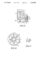
- FIG. 1 is a longitudinal sectional view of one embodiment of the scroll compressor according to the present invention.
- FIG. 2 is a plan view of an example of the orbiting scroll for the scroll compressor according to the present invention, as viewed from the wrap side;
- FIG. 3 is a plan view of the orbiting scroll shown in FIG. 2, as viewed from the back side thereof ;
- FIG. 4 is a sectional view taken along a line 4-0-4 in FIG. 2;
- FIG. 5 is an enlarged sectional view, showing the relation between the orbiting scroll and the fixed scroll of the embodiment shown in FIG. 1;
- FIG. 6 shows another example of the orbiting scroll for the scroll compressor according to the present invention.
- FIG. 7 shows a further example of the orbiting scroll for the scroll compressor according to the present invention.
- FIG. 8 is a partial side view of the orbiting scroll shown in FIG. 7;
- FIG. 9 is a plan view of another embodiment of the orbiting scroll according to the present invention, as viewed from the wrap side;
- FIG. 10 is a plan view of the orbiting scroll shown in FIG. 9, as viewed from the back side thereof;
- FIG. 11 is a sectional view taken along a line 11-0-11 in FIG. 9;
- FIG. 12 is a partial enlarged sectional view showing the orbiting scroll shown in FIGS. 9, 10 and 11, as combined with the fixed scroll and the frame;
- FIG. 13 is a plan view of another embodiment of the orbiting scroll according to the present invention, as viewed from the wrap side;
- FIG. 14 is a plan view of the orbiting scroll as shown in FIG. 13, as viewed from the back side thereof;
- FIG. 15 is a sectional view taken along a line 15-0-15 in FIG. 13;
- FIG. 16 is a plan view of a further embodiment of the orbiting scroll according to the present invention, as viewed from the back side thereof;
- FIG. 17 is a partial side view of the orbiting scroll shown in FIG. 16.
- FIGS. 1-5 will be explained.
- the scroll compressor shown in FIG. 1 includes an orbiting scroll 1 having a spiral wrap 1a and a fixed scroll 2 having a similar spiral wrap 2a.
- the orbiting scroll and the fixed scroll 2 are arranged in meshing relationship with each other, thereby constituting a compressing part.
- the fixed scroll 2 is connected with a frame 3 and fixedly mounted in a sealed housing 18.
- the orbiting scroll 1 has an end plate, which is slidably sandwiched at its peripheral portion between a surface 2c of an end plate 2b of the fixed scroll 2 and a surface 3b of the frame 3, with small gaps (not shown) being maintained therebetween, as shown in FIG. 5.
- a bearing boss 6 is formed on the back side of the end plate of the orbiting scroll
- a drive shaft 10 has an eccentric shaft portion, namely, a crank pin 10a, which is in bearing engagement with the boss 6.
- a motor 11, which is mounted in the housing 18, serves to rotate the drive shaft 10, whereby the orbiting scroll 1 produces an orbiting motion relative to the fixed scroll 2, while the rotation of the orbiting scroll about its own axis is prevented by the Oldham mechanism 8.
- a gas is introduced through a suction pipe 12 into a compressing chamber formed between the wraps of the scrolls 1, 2 and is gradually compressed as the volume of the compressing chamber is reduced.
- the compressed gas is discharged through the central discharge port 2d of the fixed scroll into an upper discharge chamber 13 and then the gas is passed through a motor chamber 14, positioned underside of the compressor, and discharged through a discharge pipe 15 to the outside of the compressor.
- the gas at an intermediate pressure, between the suction pressure and the discharge pressure, is introduced into the back pressure chamber 7 enclosed by the orbiting scroll and the frame 3, and such intermediate pressure acts on the back surface of the orbiting scroll 1, thereby generating a pressing force to press the orbiting scroll 1 toward the fixed scroll 2 in axial direction.
- the introduction of such intermediate pressure is effected by passing the gas, under a compressing process between the wraps of the both scrolls, into the back pressure chamber 7 through small holes (not shown) formed through the end plate of the orbiting scroll.
- the lubricant oil is fed from an oil reservoir 16 at the bottom in the sealed container 18, through a feeding pipe 17 and a feeding bore 20 formed in the drive shaft 10, to bearings for the drive shaft 10 supported by the frame 3 and to a bearing inserted in the boss 6 of the orbiting scroll.
- the lubricant oil also serves to lubricate the Oldham mechanism 8 and, furthermore, it passes from the back pressure chamber 7 through a space 4 formed between a marginal side 1f of the end plate of the orbiting scroll 1 and an inner side 3a opposite thereto of the frame 3 into the compressing chamber between the both scrolls, thereby lubricating the sliding surfaces of the orbiting scroll confronting the frame 2 and the fixed scroll 2. Then, the lubricant oil is discharged, together with the gas, into the discharge chamber 13.
- the gas discharged with the oil into the discharge chamber 13 is passed through the motor chamber 14 and a part of the lubricant oil is returned into the reservoir 16 and the other part of the lubricant oil is discharged, together with the gas, through the discharge pipe 15 to the outside of the compressor.
- the end plate 1b of the orbiting scroll 1 is formed with radial ribs 1c on the surface opposite to the surface on which the spiral wrap 1a is formed.
- the radial ribs 1c include a plurality of ribs which radially extend from the boss 6, which receives the eccentric shaft portion, namely, the crankpin 10a of the drive shaft 10, to the peripheral portion of the end plate 1b. Some of the radial ribs are arranged, in pairs, to form Oldham keyways.
- T indicates the sum of the thickness t of the end plate and the height h of the radial rib 1c, namely, the depth of the recess 1e formed between the radial ribs, which is constant.
- the end plate of the orbiting scroll is slidably sandwiched between the surface 3b of the frame 3 and the surface 2c of the end plate 2b of the fixed scroll, with small gaps (not shown) being maintained between the top surface of the radial rib 1c and the surface 3b of the frame 3.
- the plurality of radial ribs 1c extend substantially at a right angle to the spiral wrap 1a, thereby forming a rigid construction of the orbiting scroll, so that the thickness of the end plate 1b can be reduced, as compared to the conventional construction and thus the weight of the orbiting scroll can be reduced.
- the recesses 1e formed between the radial ribs 1c extend to the marginal side 1f of the end plate 1b and constitute lubricant oil passages which communicate the area outside of the marginal side 1f of the orbiting scroll, that is the space 4, with the back pressure chamber 7. Accordingly, the surface area of the marginal side 1f of the end plate is reduced, and passages are formed through which the lubricating oil can easily pass even when the marginal side 1f of the end plate comes near the inside surface 3a of the frame 3, as shown in FIG. 5. Therefore, the lubricant oil is not compressed by the marginal side of the end plate and, thus, the increase of load due to the compression of the lubricant oil is avoided.
- FIG. 6 illustrates an example of the orbiting scroll in which the surface area of the peripheral portion of the end plate of the orbiting scroll to contact with the surface 3b of the frame 3 is increased, with the object of decreasing the surface pressure at which the end plate of the orbiting scroll is pressed against the surface 3b of the frame 3 by the gas pressure at the time of starting of the compressor.
- a seat 5 having a height equal to that of the radial rib 1c is formed on the entire circumference of the end plate and said seat is partly cut to form small slots 5a, which communicate the area outside of the seat 5 with the respective recesses 1e.
- FIG. 7 and FIG. 8 illustrate another example, in which small holes 5b are formed in the seat 5 at several parts thereof, in place of the slots as shown in FIG. 6.
- the small holes 5b communicate the area outside of the seat 5 with the respective recesses 1e.
- the radial ribs 1c are formed on the side of the the end plate 1b of the orbiting scroll 1 opposite to the side on which the wrap 1a is formed.
- the radial ribs 1c are formed with the bearing boss 6.
- the end plate 1b has a constant thickness at the portions between these ribs 1c and recesses 1e are formed between the ribs 1c.
- the radial ribs 1c are arranged substantially at right angle to the wrap 1a, so that high rigidity of the orbiting scroll 1 is obtained, regardless of the thin thickness of the end plate 1b, and the weight of the orbiting scroll 1 can be reduced.
- the forward end portion of the radial rib 1c is integrally connected with the seat 5 which extends in circumferential direction on the peripheral portion of the end plate 1b.
- the seat 5 forms a contact surface contacting the surface 3b of the frame 3.
- the center of gravity of the orbiting scroll 1 can be located in alignment with the central axis 0 of the boss 6, by adjusting the width and consequently, the contact area, of the seat 5.
- the seat 5 is formed with cut portions 5a which communicate the space 4 outside of the marginal side of the end plate of the orbiting scroll 1 with the recesses 1e formed between the radial ribs, whereby the area of the seat 5 on the peripheral portion of the end plate 1b of the orbiting scroll is reduced and, lubricant oil passages are formed to communicate the space 4 outside of the marginal side 1f of the end pate of the orbiting scroll with the back pressure chamber 7 through the cut portions 5a and said recesses 1e.
- the sum T of the height h of the radial rib 1c, equal to the height of the seat 5 plus the thickness t of the end plate at the positions between the radial ribs 1c is slightly smaller than the distance between the surface 2c of the fixed scroll 2 and the surface 3b of the frame 3, so that the end plate of the orbiting scroll is sandwiched between the surfaces 2c and 3b, with small gaps therebetween.
- FIG. 13, FIG. 14 and FIG. 15 illustrate an embodiment in which the contact seat 5 which contacts with the frame 3, as shown in FIGS. 9, 10 and 11, is formed as a continuous part extending in peripheral direction, thereby further increasing the rigidity of the orbiting scroll.
- FIG. 16 and FIG. 17 illustrate an embodiment in which the seat 5 is formed with through-holes 5b, which constitute passages of the lubricant oil for communicating the space 4 outside of the marginal side of the end plate of the orbiting scroll 1 with the back pressure chamber 7, as in the embodiment shown in FIGS. 9, 10 and 11.
- the weight of the orbiting scroll 1 is reduced by decreasing the thickness of entire end plate 1b excluding the ribs 1c and the seat 5. Accordingly, the centrifugal force due to the weight of the orbiting scroll itself during the operation of the compressor at a high speed can be minimized, so that the bearing load can be reduced, thereby resulting in an improvement in the reliability of the compressor.
- the thickness of the end plate is decreased, the rigidity of the orbiting scroll is not lowered, due to the existence of the radial ribs 1c which extend at right angle to the spiral wrap 1a.
- the center of gravity of the orbiting scroll 1 is adjusted by adjusting the depths of the recesses formed between the radial ribs 1c, so that said center of gravity is located in alignment with the central axis of the boss 6.
- the same adjustment of the center of gravity of the orbiting scroll is effected by adjusting the contacting area or width of the contact seat 5.
- the occurrence of an unstable revolution of the orbiting scroll 1 can be avoided, whereby the occurrence of non-uniform contact between the relatively sliding parts, such as between the drive shaft and the bearing, can be avoided, and the generation of vibration and noise can be reduced.
- the lubricant oil can flow out of the space, through the recesses 1b formed between the radial ribs 1c, in the embodiment shown in FIGS. 2, 3 and 4, or the recesses 1e between the radial ribs and the cut portions 5a or the holes 5b, in the embodiments shown in FIG. 6, FIGS. 7 and 8, FIGS. 9, 10 and 11 and FIGS. 16 and 17. Accordingly, an increase of the power consumption, caused by agitation and/or compression of the lubricant oil, can be avoided.
- the orbiting scroll of the scroll compressor tends to move away from the fixed scroll due to the thrust force caused by the pressure of the compressed gas during operation of the scroll compressor.
- the orbiting scroll tending to move away from the fixed scroll by the thrust force is supported by the frame, while according to the present invention the fluid pressure introduced into the back pressure chamber acts on the back side of the end plate of the orbiting scroll, thereby pressing the orbiting scroll toward the fixed scroll against the thrust force applied to the orbiting scroll.
- the scroll compressor according to the present invention it is unnecessary to support the orbiting scroll by the frame during operation of the compressor, and it is only required to support the orbiting scroll by the frame only at the starting the compressor or when the compressor is stopped where the gas is at a low pressure.
- the provision of a small supporting area, such as the seat 5 or the ribs 1c, is enough to support the the orbiting scroll on the frame at the time of starting or stopping the compressor.
- annular portion 1c 1 which connects together the inner ends of the radial ribs 1c, and the radial portions of the radial ribs 1c may be so constructed that they extend directly from the bearing boss 6 in radial directions.
- the weight of the orbiting scroll can be considerably reduced, so that the centrifugal force caused by the orbiting scroll itself during operation of the compressor at a high speed is lowered and, consequently, the load on the bearing portions is reduced, thereby resulting in improving the reliability of the scroll compressor.
- the weight of the orbiting scroll can be reduced due to the construction and the shape of the orbiting scroll. Accordingly, the reduction of the weight of the orbiting scroll is possible even if the orbiting scroll is made of cast iron, and thus it is possible to avoid the problem arising due to the difference in coefficient of thermal expansion between the fixed scroll and the orbiting scroll if the orbiting scroll is made of aluminum alloy.
- the lubricant oil in the space between the marginal side of the end plate of the orbiting scroll and the inside surface of the frame can flow out of the space through the recesses formed between the radial ribs when the marginal side of the end plate comes close to the inside surface of the frame. Accordingly, the increase of load which may be caused by the compression of the lubricant oil in the space can be avoided.
Landscapes
- Engineering & Computer Science (AREA)
- Mechanical Engineering (AREA)
- General Engineering & Computer Science (AREA)
- Rotary Pumps (AREA)
Applications Claiming Priority (2)
| Application Number | Priority Date | Filing Date | Title |
|---|---|---|---|
| JP2-40762 | 1990-02-21 | ||
| JP4076290A JP2756014B2 (ja) | 1990-02-21 | 1990-02-21 | スクロール圧縮機 |
Publications (1)
| Publication Number | Publication Date |
|---|---|
| US5127809A true US5127809A (en) | 1992-07-07 |
Family
ID=12589638
Family Applications (1)
| Application Number | Title | Priority Date | Filing Date |
|---|---|---|---|
| US07/639,333 Expired - Lifetime US5127809A (en) | 1990-02-21 | 1991-01-10 | Scroll compressor with reinforcing ribs on the orbiting scroll |
Country Status (5)
| Country | Link |
|---|---|
| US (1) | US5127809A (de) |
| EP (1) | EP0443705B1 (de) |
| JP (1) | JP2756014B2 (de) |
| KR (1) | KR950013894B1 (de) |
| ES (1) | ES2046011T3 (de) |
Cited By (27)
| Publication number | Priority date | Publication date | Assignee | Title |
|---|---|---|---|---|
| WO1995027143A1 (en) * | 1994-04-05 | 1995-10-12 | Puritan-Bennett Corporation | Scroll compressor |
| US6244840B1 (en) * | 1999-06-08 | 2001-06-12 | Mitsubishi Heavy Industries, Ltd. | Scroll compressor having end plates of fixed and revolving scrolls thicker than heights of spiral protrusions of the scrolls |
| US6358028B1 (en) * | 1998-10-15 | 2002-03-19 | Hitachi, Ltd. | Scroll compressor |
| US6439864B1 (en) | 1999-01-11 | 2002-08-27 | Air Squared, Inc. | Two stage scroll vacuum pump with improved pressure ratio and performance |
| US6494695B1 (en) * | 2000-09-19 | 2002-12-17 | Scroll Technologies | Orbiting scroll center of mass optimization |
| US20050214148A1 (en) * | 2004-03-24 | 2005-09-29 | Nippon Soken, Inc | Fluid machine |
| US20060222546A1 (en) * | 2005-03-30 | 2006-10-05 | Lg Electronics Inc. | Fixed scroll of scroll compressor |
| US20060266076A1 (en) * | 2005-05-31 | 2006-11-30 | Scroll Technologies | Indentation to optimize vapor injection through ports extending through scroll wrap |
| CN100404790C (zh) * | 2004-03-24 | 2008-07-23 | 株式会社日本自动车部品综合研究所 | 流体机械 |
| WO2019057056A1 (zh) * | 2017-09-19 | 2019-03-28 | 艾默生环境优化技术(苏州)有限公司 | 用于涡旋压缩机的动涡旋装置及其制造方法及涡旋压缩机 |
| US10508543B2 (en) | 2015-05-07 | 2019-12-17 | Air Squared, Inc. | Scroll device having a pressure plate |
| US10519815B2 (en) | 2011-08-09 | 2019-12-31 | Air Squared, Inc. | Compact energy cycle construction utilizing some combination of a scroll type expander, pump, and compressor for operating according to a rankine, an organic rankine, heat pump or combined organic rankine and heat pump cycle |
| US10683865B2 (en) | 2006-02-14 | 2020-06-16 | Air Squared, Inc. | Scroll type device incorporating spinning or co-rotating scrolls |
| US10865793B2 (en) | 2016-12-06 | 2020-12-15 | Air Squared, Inc. | Scroll type device having liquid cooling through idler shafts |
| US11022121B2 (en) | 2018-07-05 | 2021-06-01 | Daikin Industries, Ltd. | Scroll compressor |
| US11047389B2 (en) | 2010-04-16 | 2021-06-29 | Air Squared, Inc. | Multi-stage scroll vacuum pumps and related scroll devices |
| US11067080B2 (en) | 2018-07-17 | 2021-07-20 | Air Squared, Inc. | Low cost scroll compressor or vacuum pump |
| CN114109817A (zh) * | 2020-08-31 | 2022-03-01 | 丹佛斯(天津)有限公司 | 静涡旋盘和具有该静涡旋盘的涡旋压缩机 |
| US20220065245A1 (en) * | 2020-08-31 | 2022-03-03 | Danfoss (Tianjin) Ltd. | Fixed scroll disk and scroll compressor having the same |
| US11333147B2 (en) * | 2018-01-17 | 2022-05-17 | Daikin Industries, Ltd. | Scroll compressor including an orbiting scroll having an orbiting end plate provided with a rear concave portion |
| US11454241B2 (en) | 2018-05-04 | 2022-09-27 | Air Squared, Inc. | Liquid cooling of fixed and orbiting scroll compressor, expander or vacuum pump |
| US11473572B2 (en) | 2019-06-25 | 2022-10-18 | Air Squared, Inc. | Aftercooler for cooling compressed working fluid |
| US11530703B2 (en) | 2018-07-18 | 2022-12-20 | Air Squared, Inc. | Orbiting scroll device lubrication |
| US20230400023A1 (en) * | 2022-06-09 | 2023-12-14 | Hanon Systems | Orbit scroll platter mass reduction |
| US11885328B2 (en) | 2021-07-19 | 2024-01-30 | Air Squared, Inc. | Scroll device with an integrated cooling loop |
| US11898557B2 (en) | 2020-11-30 | 2024-02-13 | Air Squared, Inc. | Liquid cooling of a scroll type compressor with liquid supply through the crankshaft |
| US11933299B2 (en) | 2018-07-17 | 2024-03-19 | Air Squared, Inc. | Dual drive co-rotating spinning scroll compressor or expander |
Families Citing this family (3)
| Publication number | Priority date | Publication date | Assignee | Title |
|---|---|---|---|---|
| GB2255595A (en) * | 1991-05-06 | 1992-11-11 | Volkswagen Ag | Spiral bladed compressor. |
| JP2007170285A (ja) * | 2005-12-22 | 2007-07-05 | Yanmar Co Ltd | スクロール形流体機械 |
| JP7620557B2 (ja) * | 2019-09-20 | 2025-01-23 | 株式会社ヴァレオジャパン | スクロール圧縮機 |
Citations (6)
| Publication number | Priority date | Publication date | Assignee | Title |
|---|---|---|---|---|
| JPS58110886A (ja) * | 1981-12-25 | 1983-07-01 | Hitachi Ltd | スクロ−ル流体機械 |
| JPS59119091A (ja) * | 1982-12-24 | 1984-07-10 | Hitachi Ltd | スクロ−ル形流体機械 |
| US4472120A (en) * | 1982-07-15 | 1984-09-18 | Arthur D. Little, Inc. | Scroll type fluid displacement apparatus |
| US4502852A (en) * | 1981-04-17 | 1985-03-05 | Hitachi, Ltd. | Oil feeding device for scroll fluid apparatus |
| JPS60233388A (ja) * | 1984-05-07 | 1985-11-20 | Hitachi Ltd | スクロ−ル流体機械 |
| JPH01130081A (ja) * | 1987-11-12 | 1989-05-23 | Sanyo Electric Co Ltd | スクロール圧縮機 |
Family Cites Families (3)
| Publication number | Priority date | Publication date | Assignee | Title |
|---|---|---|---|---|
| US4596521A (en) * | 1982-12-17 | 1986-06-24 | Hitachi, Ltd. | Scroll fluid apparatus |
| JPS61126095U (de) * | 1985-01-28 | 1986-08-07 | ||
| JPS6332182A (ja) * | 1986-07-25 | 1988-02-10 | Mitsui Seiki Kogyo Co Ltd | スクロ−ル圧縮機 |
-
1990
- 1990-02-21 JP JP4076290A patent/JP2756014B2/ja not_active Expired - Fee Related
-
1991
- 1991-01-08 EP EP19910300121 patent/EP0443705B1/de not_active Expired - Lifetime
- 1991-01-08 KR KR1019910000164A patent/KR950013894B1/ko not_active Expired - Fee Related
- 1991-01-08 ES ES91300121T patent/ES2046011T3/es not_active Expired - Lifetime
- 1991-01-10 US US07/639,333 patent/US5127809A/en not_active Expired - Lifetime
Patent Citations (6)
| Publication number | Priority date | Publication date | Assignee | Title |
|---|---|---|---|---|
| US4502852A (en) * | 1981-04-17 | 1985-03-05 | Hitachi, Ltd. | Oil feeding device for scroll fluid apparatus |
| JPS58110886A (ja) * | 1981-12-25 | 1983-07-01 | Hitachi Ltd | スクロ−ル流体機械 |
| US4472120A (en) * | 1982-07-15 | 1984-09-18 | Arthur D. Little, Inc. | Scroll type fluid displacement apparatus |
| JPS59119091A (ja) * | 1982-12-24 | 1984-07-10 | Hitachi Ltd | スクロ−ル形流体機械 |
| JPS60233388A (ja) * | 1984-05-07 | 1985-11-20 | Hitachi Ltd | スクロ−ル流体機械 |
| JPH01130081A (ja) * | 1987-11-12 | 1989-05-23 | Sanyo Electric Co Ltd | スクロール圧縮機 |
Cited By (38)
| Publication number | Priority date | Publication date | Assignee | Title |
|---|---|---|---|---|
| US5466134A (en) * | 1994-04-05 | 1995-11-14 | Puritan Bennett Corporation | Scroll compressor having idler cranks and strengthening and heat dissipating ribs |
| EP0754274A4 (de) * | 1994-04-05 | 1998-09-09 | Puritan Bennett Corp | Rollenkompressor |
| WO1995027143A1 (en) * | 1994-04-05 | 1995-10-12 | Puritan-Bennett Corporation | Scroll compressor |
| US6358028B1 (en) * | 1998-10-15 | 2002-03-19 | Hitachi, Ltd. | Scroll compressor |
| US6439864B1 (en) | 1999-01-11 | 2002-08-27 | Air Squared, Inc. | Two stage scroll vacuum pump with improved pressure ratio and performance |
| US6244840B1 (en) * | 1999-06-08 | 2001-06-12 | Mitsubishi Heavy Industries, Ltd. | Scroll compressor having end plates of fixed and revolving scrolls thicker than heights of spiral protrusions of the scrolls |
| US6494695B1 (en) * | 2000-09-19 | 2002-12-17 | Scroll Technologies | Orbiting scroll center of mass optimization |
| US7314356B2 (en) * | 2004-03-24 | 2008-01-01 | Nippon Soken, Inc. | Fluid machine |
| US20050214148A1 (en) * | 2004-03-24 | 2005-09-29 | Nippon Soken, Inc | Fluid machine |
| CN100404790C (zh) * | 2004-03-24 | 2008-07-23 | 株式会社日本自动车部品综合研究所 | 流体机械 |
| US20060222546A1 (en) * | 2005-03-30 | 2006-10-05 | Lg Electronics Inc. | Fixed scroll of scroll compressor |
| US7318710B2 (en) * | 2005-03-30 | 2008-01-15 | Lg Electronics Inc. | Fixed scroll of scroll compressor |
| US7228710B2 (en) * | 2005-05-31 | 2007-06-12 | Scroll Technologies | Indentation to optimize vapor injection through ports extending through scroll wrap |
| US20060266076A1 (en) * | 2005-05-31 | 2006-11-30 | Scroll Technologies | Indentation to optimize vapor injection through ports extending through scroll wrap |
| US10683865B2 (en) | 2006-02-14 | 2020-06-16 | Air Squared, Inc. | Scroll type device incorporating spinning or co-rotating scrolls |
| US11047389B2 (en) | 2010-04-16 | 2021-06-29 | Air Squared, Inc. | Multi-stage scroll vacuum pumps and related scroll devices |
| US10774690B2 (en) | 2011-08-09 | 2020-09-15 | Air Squared, Inc. | Compact energy cycle construction utilizing some combination of a scroll type expander, pump, and compressor for operating according to a rankine, an organic rankine, heat pump, or combined organic rankine and heat pump cycle |
| US10519815B2 (en) | 2011-08-09 | 2019-12-31 | Air Squared, Inc. | Compact energy cycle construction utilizing some combination of a scroll type expander, pump, and compressor for operating according to a rankine, an organic rankine, heat pump or combined organic rankine and heat pump cycle |
| US10508543B2 (en) | 2015-05-07 | 2019-12-17 | Air Squared, Inc. | Scroll device having a pressure plate |
| US10865793B2 (en) | 2016-12-06 | 2020-12-15 | Air Squared, Inc. | Scroll type device having liquid cooling through idler shafts |
| US11692550B2 (en) | 2016-12-06 | 2023-07-04 | Air Squared, Inc. | Scroll type device having liquid cooling through idler shafts |
| US11674511B2 (en) | 2017-09-19 | 2023-06-13 | Emerson Climate Technologies (Suzhou) Co., Ltd. | Hub of movable scroll device for scroll compressor including centroid-adjusting recess and method for manufacturing same |
| WO2019057056A1 (zh) * | 2017-09-19 | 2019-03-28 | 艾默生环境优化技术(苏州)有限公司 | 用于涡旋压缩机的动涡旋装置及其制造方法及涡旋压缩机 |
| US11333147B2 (en) * | 2018-01-17 | 2022-05-17 | Daikin Industries, Ltd. | Scroll compressor including an orbiting scroll having an orbiting end plate provided with a rear concave portion |
| US11454241B2 (en) | 2018-05-04 | 2022-09-27 | Air Squared, Inc. | Liquid cooling of fixed and orbiting scroll compressor, expander or vacuum pump |
| US11022121B2 (en) | 2018-07-05 | 2021-06-01 | Daikin Industries, Ltd. | Scroll compressor |
| US11067080B2 (en) | 2018-07-17 | 2021-07-20 | Air Squared, Inc. | Low cost scroll compressor or vacuum pump |
| US11933299B2 (en) | 2018-07-17 | 2024-03-19 | Air Squared, Inc. | Dual drive co-rotating spinning scroll compressor or expander |
| US11530703B2 (en) | 2018-07-18 | 2022-12-20 | Air Squared, Inc. | Orbiting scroll device lubrication |
| US11473572B2 (en) | 2019-06-25 | 2022-10-18 | Air Squared, Inc. | Aftercooler for cooling compressed working fluid |
| US12044226B2 (en) | 2019-06-25 | 2024-07-23 | Air Squared, Inc. | Liquid cooling aftercooler |
| US20220065245A1 (en) * | 2020-08-31 | 2022-03-03 | Danfoss (Tianjin) Ltd. | Fixed scroll disk and scroll compressor having the same |
| US11767844B2 (en) * | 2020-08-31 | 2023-09-26 | Danfoss (Tianjin) Ltd. | Fixed scroll disk and scroll compressor having the same |
| CN114109817A (zh) * | 2020-08-31 | 2022-03-01 | 丹佛斯(天津)有限公司 | 静涡旋盘和具有该静涡旋盘的涡旋压缩机 |
| US11898557B2 (en) | 2020-11-30 | 2024-02-13 | Air Squared, Inc. | Liquid cooling of a scroll type compressor with liquid supply through the crankshaft |
| US11885328B2 (en) | 2021-07-19 | 2024-01-30 | Air Squared, Inc. | Scroll device with an integrated cooling loop |
| US20230400023A1 (en) * | 2022-06-09 | 2023-12-14 | Hanon Systems | Orbit scroll platter mass reduction |
| US12117000B2 (en) * | 2022-06-09 | 2024-10-15 | Hanon Systems | Orbiting scroll platter mass reduction |
Also Published As
| Publication number | Publication date |
|---|---|
| KR950013894B1 (ko) | 1995-11-17 |
| JP2756014B2 (ja) | 1998-05-25 |
| EP0443705B1 (de) | 1993-09-22 |
| ES2046011T3 (es) | 1994-01-16 |
| EP0443705A1 (de) | 1991-08-28 |
| JPH03242484A (ja) | 1991-10-29 |
| KR910021539A (ko) | 1991-12-20 |
Similar Documents
| Publication | Publication Date | Title |
|---|---|---|
| US5127809A (en) | Scroll compressor with reinforcing ribs on the orbiting scroll | |
| EP1260713B1 (de) | Spiralverdichter mit einer Oldham Kupplung | |
| US4836758A (en) | Scroll compressor with canted drive busing surface | |
| US4734020A (en) | Scroll type compressor with spiral oil feeding grooves in thrust bearing | |
| JPH0553953B2 (de) | ||
| US20080304994A1 (en) | Scroll Fluid Machine | |
| EP0498164A1 (de) | Spiralverdichter | |
| US5104302A (en) | Scroll compressor including drive pin and roller assembly having sliding wedge member | |
| US4473343A (en) | Bearing device for scroll-type compressor | |
| US5730588A (en) | Scroll compressor having a fixed scroll plate with groove | |
| JPH0135196B2 (de) | ||
| EP0348601A2 (de) | Spiral-Verdichter | |
| JPH06317271A (ja) | 密閉形スクロール圧縮機 | |
| JP3737563B2 (ja) | スクロール圧縮機 | |
| JP2557533B2 (ja) | 密閉型可変速スクロール圧縮機 | |
| CN114867941B (zh) | 涡旋式流体机械 | |
| JP3545826B2 (ja) | スクロ−ル圧縮機 | |
| KR101970529B1 (ko) | 전동식 압축기 | |
| US4904169A (en) | Scroll type compressing apparatus having strengthened scroll member | |
| JP2705656B2 (ja) | スクロール圧縮機 | |
| JPH0541838B2 (de) | ||
| JP2004124780A (ja) | スクロール圧縮機 | |
| JPH08319959A (ja) | スクロール圧縮機 | |
| JPH0515609Y2 (de) | ||
| JPH03294682A (ja) | スクロール圧縮機 |
Legal Events
| Date | Code | Title | Description |
|---|---|---|---|
| AS | Assignment |
Owner name: HITACHI, LTD., 6, KANDA SURUGADAI 4-CHOME, CHIYODA Free format text: ASSIGNMENT OF ASSIGNORS INTEREST.;ASSIGNORS:AMATA, ATUSHI;MIZUNO, TAKAO;UCHIKAWA, NAOSHI;REEL/FRAME:005571/0904 Effective date: 19901221 |
|
| STCF | Information on status: patent grant |
Free format text: PATENTED CASE |
|
| FEPP | Fee payment procedure |
Free format text: PAYOR NUMBER ASSIGNED (ORIGINAL EVENT CODE: ASPN); ENTITY STATUS OF PATENT OWNER: LARGE ENTITY |
|
| REFU | Refund |
Free format text: REFUND OF EXCESS PAYMENTS PROCESSED (ORIGINAL EVENT CODE: R169); ENTITY STATUS OF PATENT OWNER: LARGE ENTITY |
|
| FPAY | Fee payment |
Year of fee payment: 4 |
|
| FPAY | Fee payment |
Year of fee payment: 8 |
|
| FPAY | Fee payment |
Year of fee payment: 12 |