US5121533A - Fitting method utilizing both continuous and intermittent ultrasonic vibration - Google Patents
Fitting method utilizing both continuous and intermittent ultrasonic vibration Download PDFInfo
- Publication number
- US5121533A US5121533A US07/702,119 US70211991A US5121533A US 5121533 A US5121533 A US 5121533A US 70211991 A US70211991 A US 70211991A US 5121533 A US5121533 A US 5121533A
- Authority
- US
- United States
- Prior art keywords
- pin
- vibration
- ultrasonic vibration
- fitting
- clearance
- Prior art date
- Legal status (The legal status is an assumption and is not a legal conclusion. Google has not performed a legal analysis and makes no representation as to the accuracy of the status listed.)
- Expired - Lifetime
Links
Images


Classifications
-
- B—PERFORMING OPERATIONS; TRANSPORTING
- B23—MACHINE TOOLS; METAL-WORKING NOT OTHERWISE PROVIDED FOR
- B23P—METAL-WORKING NOT OTHERWISE PROVIDED FOR; COMBINED OPERATIONS; UNIVERSAL MACHINE TOOLS
- B23P19/00—Machines for simply fitting together or separating metal parts or objects, or metal and non-metal parts, whether or not involving some deformation; Tools or devices therefor so far as not provided for in other classes
- B23P19/02—Machines for simply fitting together or separating metal parts or objects, or metal and non-metal parts, whether or not involving some deformation; Tools or devices therefor so far as not provided for in other classes for connecting objects by press fit or for detaching same
- B23P19/033—Machines for simply fitting together or separating metal parts or objects, or metal and non-metal parts, whether or not involving some deformation; Tools or devices therefor so far as not provided for in other classes for connecting objects by press fit or for detaching same using vibration
-
- B—PERFORMING OPERATIONS; TRANSPORTING
- B25—HAND TOOLS; PORTABLE POWER-DRIVEN TOOLS; MANIPULATORS
- B25B—TOOLS OR BENCH DEVICES NOT OTHERWISE PROVIDED FOR, FOR FASTENING, CONNECTING, DISENGAGING OR HOLDING
- B25B27/00—Hand tools, specially adapted for fitting together or separating parts or objects whether or not involving some deformation, not otherwise provided for
- B25B27/02—Hand tools, specially adapted for fitting together or separating parts or objects whether or not involving some deformation, not otherwise provided for for connecting objects by press fit or detaching same
-
- Y—GENERAL TAGGING OF NEW TECHNOLOGICAL DEVELOPMENTS; GENERAL TAGGING OF CROSS-SECTIONAL TECHNOLOGIES SPANNING OVER SEVERAL SECTIONS OF THE IPC; TECHNICAL SUBJECTS COVERED BY FORMER USPC CROSS-REFERENCE ART COLLECTIONS [XRACs] AND DIGESTS
- Y10—TECHNICAL SUBJECTS COVERED BY FORMER USPC
- Y10S—TECHNICAL SUBJECTS COVERED BY FORMER USPC CROSS-REFERENCE ART COLLECTIONS [XRACs] AND DIGESTS
- Y10S29/00—Metal working
- Y10S29/046—Vibration
-
- Y—GENERAL TAGGING OF NEW TECHNOLOGICAL DEVELOPMENTS; GENERAL TAGGING OF CROSS-SECTIONAL TECHNOLOGIES SPANNING OVER SEVERAL SECTIONS OF THE IPC; TECHNICAL SUBJECTS COVERED BY FORMER USPC CROSS-REFERENCE ART COLLECTIONS [XRACs] AND DIGESTS
- Y10—TECHNICAL SUBJECTS COVERED BY FORMER USPC
- Y10T—TECHNICAL SUBJECTS COVERED BY FORMER US CLASSIFICATION
- Y10T29/00—Metal working
- Y10T29/49—Method of mechanical manufacture
- Y10T29/49764—Method of mechanical manufacture with testing or indicating
- Y10T29/49771—Quantitative measuring or gauging
- Y10T29/49774—Quantitative measuring or gauging by vibratory or oscillatory movement
-
- Y—GENERAL TAGGING OF NEW TECHNOLOGICAL DEVELOPMENTS; GENERAL TAGGING OF CROSS-SECTIONAL TECHNOLOGIES SPANNING OVER SEVERAL SECTIONS OF THE IPC; TECHNICAL SUBJECTS COVERED BY FORMER USPC CROSS-REFERENCE ART COLLECTIONS [XRACs] AND DIGESTS
- Y10—TECHNICAL SUBJECTS COVERED BY FORMER USPC
- Y10T—TECHNICAL SUBJECTS COVERED BY FORMER US CLASSIFICATION
- Y10T29/00—Metal working
- Y10T29/49—Method of mechanical manufacture
- Y10T29/49826—Assembling or joining
- Y10T29/49945—Assembling or joining by driven force fit
Definitions
- the present invention relates to a fitting of a member in another, with clearance of several microns or less or even negative clearance, and, particularly, to a method of fitting of two members without gouging and with reduced insertion force.
- Japanese Patent Application Laid-Open No. 224711/1987 discloses a fitting apparatus such as shown in FIG. 5 of this application.
- a ultrasonic vibration apparatus 41 is constituted with a vibrator 1 and a stepped hone 2 connected to the vibrator 1.
- a pin 3 to be inserted into a hole of a part 6 is held in contact with an end of the hone 2 and supported substantially coaxially with the hone 2 by a circular ring 4 provided on a sample holder 5.
- the ring 4 may be movable horizontally within a limited distance of several millimeters.
- the part 6 is supported by a hand portion 7 mounted on an arm 8 of a multi-articulation robot having freedom in a horizontal plane and an altitude and position of the part 6 are controlled by the robot in such a way that the hole of the part 6 is substantially coaxial with the pin 3.
- a fitting of the pin 3 in the hole of the part 6 starts by lowering the part 6 on the robot arm 8.
- the pin 3 commences to enter into the hole of the part 6, frictional force is generated therebetween and the pin 3 is urged, by resultant contact reaction, to a top end of the hone 2 on the ultrasonic vibration apparatus 41, by which ultrasonic vibration is transmitted to the pin 3 which just starts to enter into the hole.
- the pin 3 is vibrated at a composite frequency of a resonance frequency of the ultrasonic vibrator and a specific frequency of the pin 3. Since amplitude of vibration of the pin 3 is maximum at the top end thereof, frictional force in the contact plane thereof with the part 6 is substantially reduced.
- a reference numeral 9 depicts a pin and 10 a hole in which the pin 9 is to be fitted. Since the pin 9 vibrates at ultrasonic frequency, it deforms in axial and radial directions alternately as shown by dotted lines in FIG. 6a, in which the pin 9 is shown as being tilted with respect to the hole 10.
- a top end of the pin 9 contacts with a point A of an inner surface of the hole 10 when the pin 9 is extended axially while being shrinked radially. Due to the axial vibration of the pin 9, friction force at the portion A is substantially reduced.
- portion B of an edge of the hole 10 is cleared by the pin 9 when the latter is extended axially while being shrinked radially as shown in FIG. 6a.
- top portion of the pin 9 is received in the hole 10.
- the inclination of the pin 9 with respect to the hole 10 is corrected by reaction of a contact of a side surface of the pin 9 with the edge of the hole 10 by an axial shrinkage and radial expansion of the pin 9, as shown in FIG. 6b.
- the clearance between the pin 9 and the hole 10 is temporarily enlarged, facilitating the insertion of the pin into the hole.
- FIG. 7a shows a construction of the apparatus used in this experiment.
- a vibrator 11, a stepped hone 12, a pin 13, a circular ring 14 movable horizontally on a sample support table 15, a part 16 having a hole in which the pin 13 is to be fitted, a robot hand portion 17 and a robot arm 8 are substantially the same as those depicted by reference numerals 1, 2, 3, 4, 6, 7 and 8 in FIG. 5, respectively.
- a load sensor 17 is provided.
- FIG. 7b shows a structure of the sensor 17 in detail.
- a load cell 19 is provided for measuring of vertical load or insertion force and a cross shaped plate spring 20 is provided for detection of movements around two mutually orthogonal axes which are also orthogonal to a direction of pin insertion.
- the spring 20 is fixedly secured to an intermedial portion of a support stud 21 which connected to the part 16, and is provided on four arms thereof with strain gauges 22.
- the load sensor 17 is supported, together with the part 16, by a robot arm 18, with the pin 13 being inserted into the hole of the part by lowering the robot arm 18.
- a diameter of the pin 13 was 20 mm and an inner diameter of the hole of the part 16 was selected such that a clearance, i.e., a difference between the outer diameter of the pin and the inner diameter of the hole is 2 ⁇ m.
- FIGS. 8 and 9 Results of the experiment are shown in FIGS. 8 and 9 for insertion without vibration and for that with vibration, respectively.
- waveforms A and B show moments Mx and My around mutually orthogonal axes orthogonal to a direction of insertion, respectively, which are criteria of catching of the pin by the inner wall of the hole
- waveforms C and D show a vertical load insertion force Fz and a position of the robot arm or insertion amount, respectively.
- abscissa shows time.
- the ultrasonic vibration apparatus 41 used in the assembling robot shown in FIG. 5 is energized immediately before a commencement of insertion operation after the pin 3 is aligned with the hole of the part 6 within a positional error tolerance corresponding to a chamfered portion of the pin 3 and deenergized when the insertion depth becomes equal to a desired value.
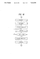
- FIG. 10 is a flowchart showing this operation. Since the ultrasonic vibration apparatus is energized in a short period in an insertion stage, heat generation of the vibrator is minimized, resulting in a elongation of life time of the ultrasonic vibration device.
- a solid member has a specific resonance frequency determined by its physical condition.
- vibration is transmitted to such solid member as the pin 3 through a rigid coupling, it is difficult to obtain a resonation or it is necessary to make the coupling special in configuration. Therefore, it is impossible, in such system, to insert a pin 3 having arbitrary configuration into a hole while applying vibration thereto.
- the assembling fitting by means of the conventional robot is possible with clearance in the order of 10 ⁇ m while correcting the inclination of the pin with respect to the hole of the part and, for fitting with clearance in the order of several ⁇ m, the application of ultrasonic vibration is effective.
- An object of the present invention is to provide a fitting method applicable to a fitting between two members with minute or negative clearance.
- the fitting method according to the present invention is characterized by continuously applying ultrasonic vibration to either or both of the members until a fitting is achieved to a desired depth and thereafter intermittently applying ultrasonic vibration to either or both of the members so that friction therebetween is reduced and inclination of one member to be fitted in the other due to eccentricity of contract reaction force is removed.
- FIG. 1 shows a model for explaining an operation of an embodiment of the present invention
- FIG. 2 is a graph showing a relation between ultrasonic vibration and clearance obtained by an experimental device used to confirm the effect of the present invention
- FIG. 3 is a graph showing the relation between vertical load and clearance for cases where ultrasonic vibration is intermittent and continuous, respectively;
- FIG. 4 is a graph showing a load variation with time during insertion
- FIG. 5 shows a construction of a fitting apparatus using ultrasonic vibration
- FIG. 6 is a conceptional model showing an operation
- FIG. 7a is a constitution of an experimental apparatus used to confirm the effect of the present invention.
- FIG. 7b is a detail of a load sensor portion
- FIG. 8 is a graph showing a result obtained by the experimental apparatus in FIG. 7a when no vibration is applied;
- FIG. 9 is a similar graph to that in FIG. 8 when vibration is applied.
- FIG. 10 is a flowchart showing an operation of an ultrasonic vibration apparatus.
- FIG. 11 shows vibration waveforms observed for insertion pins pressurized or shocked by an ultrasonic vibrator.
- FIG. 1 shows a model representing an operations of an embodiment of the present invention, in which a reference numeral 42 depicts an insertion pin and 43 a part having a hole in which the insertion pin 42 is to be fitted.
- a top portion of the pin 42 and an edge portion of the hole of the part 43 are chamfered to form chamfers 42a and 43a, respectively.
- An angle ⁇ of the chamfer 42a of the insertion pin 42 and an angle ⁇ of the chamber 43a of the part 43 satisfy a relation ⁇ .
- the insertion pin 42 is mounted on a cross-head (not shown) and, by lowering the cross head, the pin 42 is positioned with respect to the part 43 by the chamfer 42a of the pin 42 and the chamfer 43a of the part 43 so that the pin 42 is guided smoothly to the hole of the part 43 to start an insertion.
- the fitting operation proceeds with a pushing force due to lowering of the pin 42 to which ultrasonic vibration is transmitted through a hone (not shown) through which the same vibration is also transmitted to the part 43.
- the pin 42 vibrates at a composite frequency of resonance frequency of the ultrasonic vibration and specific frequency of the pin 42.
- An amplitude of vibration of the pin 42 is maximum at a top end portion thereof and, therefore, friction between the top end and a portion of the part which is in contact thereof is substantially reduced to provide a smooth contact plane. Since the pin 42 is subjected to alternative radial expansion and shrink, a clearance between the pin 42 and the part 43 is increased temporarily in fitted condition, facilitating a further fitting with minimum insertion force.
- grind-finished pins (SK3 heat treated, Hv 520-700) having a common diameter of 20 mm and lengths 50 mm and 65 mm, respectively, were used and, for the part 43, a corresponding part (S45C heat treated, Hv 150-250) was used.
- Pins having diameter from 4 to 11 mm were also prepared and tested. Each pin is of SCM415 (Hv 650-800) and grind-finished. Corresponding parts 43 were reamerfinished parts of S45C content-regulated material (Hv 200-300).
- the vibration was applied in two ways, one being continuous application and the other being intermittent application. In the latter case, a pressure apparatus is stopped and vibration is applied every time a load reaches a certain value and after the load reduces, vibration is applied again.
- FIG. 2 shows a result of experiment performed with the test sample having diameter of 4 mm.
- the load reaches about 60 kgf with clearance of 2 ⁇ m.
- the load is substantially null provided that clearance is several ⁇ m or more. Further the insertion load is not more than 50 kgf even if the clearance is smaller than several ⁇ m, so long as the clearance is positive.
- FIG. 3 shows a result of experiment performed with the test sample having diameter of 20 mm with negative clearance, in which the effect of intermittent application of ultrasonic vibration, the load increased substantially respective clearances.
- the load increased substantially linearly for clearance from positive several ⁇ m to negative several ⁇ m although there are some exceptions.
- the insertion load is reduced.
- FIG. 4 shows a load variation with time, during an insertion with clearance of -2 ⁇ m.
- application of vibration was started at a point A in the initial insertion stage.
- the load increased abruptly at a point B corresponding to an insertion depth of 2-3 mm, the application of vibration was switched from continuous to intermittent.
- the variation of insertion load was limited to 15 to 38 kgf. Thus, undesired increase of variation was prevented.
- the insertion pressure becomes substantially null by application of vibration.
- the chamfers of the top end of the pin 42 and the edge of the part 43 a fitting is easily realized even if the relative positioning control of them is very rough.
- the embodiment is described as to the case where the pin 42 is fitted in the part 43 while applying ultrasonic vibration to the pin, it is possible to apply ultrasonic vibration to not the pin but the part 43 or to apply it to both the pin and the part.
- chamfer or chamfers may be not always flat, and rounded edges such as shown by 43b in FIG. 1b may be used. In the later case, it is preferable that the angle of chamfer of the insertion side member is smaller than that of the chamfer of the receiving side member.
- the present invention is applicable to a case where a pin fitted in a hole of a part is to be removed from the latter.
- ultrasonic vibration is applied continuously to either or both of a first member and a second member in which the first member is to be fitted until an insertion depth of the first member in the second member becomes a predetermined value and then intermittently until the insertion completes.
- friction between the members is reduced and an inclination of the first member with respect to the second member due to contact reaction is avoided. Therefore, a precision fitting of the members with minute clearance therebetween or with even negative clearance can be realized with minimum insertion force. Further, a removal of the insertion member from the receiving member is also realized without damage of fitting surfaces.
Landscapes
- Engineering & Computer Science (AREA)
- Mechanical Engineering (AREA)
- Automatic Assembly (AREA)
Applications Claiming Priority (2)
| Application Number | Priority Date | Filing Date | Title |
|---|---|---|---|
| JP63-60759 | 1988-03-15 | ||
| JP63060759A JPH01234128A (ja) | 1988-03-15 | 1988-03-15 | 嵌合方法 |
Related Parent Applications (1)
| Application Number | Title | Priority Date | Filing Date |
|---|---|---|---|
| US07596615 Continuation | 1990-10-12 |
Publications (1)
| Publication Number | Publication Date |
|---|---|
| US5121533A true US5121533A (en) | 1992-06-16 |
Family
ID=13151526
Family Applications (1)
| Application Number | Title | Priority Date | Filing Date |
|---|---|---|---|
| US07/702,119 Expired - Lifetime US5121533A (en) | 1988-03-15 | 1991-05-16 | Fitting method utilizing both continuous and intermittent ultrasonic vibration |
Country Status (2)
| Country | Link |
|---|---|
| US (1) | US5121533A (de) |
| JP (1) | JPH01234128A (de) |
Cited By (3)
| Publication number | Priority date | Publication date | Assignee | Title |
|---|---|---|---|---|
| US5701388A (en) * | 1994-12-22 | 1997-12-23 | Kohler Co. | Combined heater and pump |
| FR2784718A1 (fr) * | 1998-10-14 | 2000-04-21 | Sanden Corp | Compresseur a plateau incline a deplacement variable |
| DE102007007814A1 (de) * | 2007-02-16 | 2008-08-21 | Siemens Ag | Verfahren und Vorrichtung zum Einführen eines Werkstücks in eine Bohrung eines Trägers des Werkstücks |
Families Citing this family (5)
| Publication number | Priority date | Publication date | Assignee | Title |
|---|---|---|---|---|
| FR2721849B1 (fr) * | 1994-07-04 | 1996-08-23 | Ind Automation Sa | Dispositif pour introduire des pistons dan des cylindres ou des chemises, notamment d'un moteur a combustion interne |
| JP2003028197A (ja) * | 2001-07-19 | 2003-01-29 | Nsk Warner Kk | ワンウェイクラッチ装置 |
| JP2007296615A (ja) * | 2006-05-01 | 2007-11-15 | Toyota Motor Corp | 超音波圧入装置 |
| JP4724144B2 (ja) * | 2007-03-30 | 2011-07-13 | トヨタ自動車株式会社 | 推力加工装置及び推力加工方法 |
| JP4793694B2 (ja) * | 2007-04-18 | 2011-10-12 | 株式会社安川電機 | ロボットの制御方法、ロボット制御装置およびロボット制御システム |
Citations (2)
| Publication number | Priority date | Publication date | Assignee | Title |
|---|---|---|---|---|
| US3224086A (en) * | 1961-11-13 | 1965-12-21 | Cavitron Ultrasonics Inc | Method of high frequency vibration fitting |
| SU457577A2 (ru) * | 1973-10-02 | 1975-01-25 | Севастопольский Приборостроительный Институт | Способ комплектовани пар деталей |
-
1988
- 1988-03-15 JP JP63060759A patent/JPH01234128A/ja active Granted
-
1991
- 1991-05-16 US US07/702,119 patent/US5121533A/en not_active Expired - Lifetime
Patent Citations (2)
| Publication number | Priority date | Publication date | Assignee | Title |
|---|---|---|---|---|
| US3224086A (en) * | 1961-11-13 | 1965-12-21 | Cavitron Ultrasonics Inc | Method of high frequency vibration fitting |
| SU457577A2 (ru) * | 1973-10-02 | 1975-01-25 | Севастопольский Приборостроительный Институт | Способ комплектовани пар деталей |
Cited By (3)
| Publication number | Priority date | Publication date | Assignee | Title |
|---|---|---|---|---|
| US5701388A (en) * | 1994-12-22 | 1997-12-23 | Kohler Co. | Combined heater and pump |
| FR2784718A1 (fr) * | 1998-10-14 | 2000-04-21 | Sanden Corp | Compresseur a plateau incline a deplacement variable |
| DE102007007814A1 (de) * | 2007-02-16 | 2008-08-21 | Siemens Ag | Verfahren und Vorrichtung zum Einführen eines Werkstücks in eine Bohrung eines Trägers des Werkstücks |
Also Published As
| Publication number | Publication date |
|---|---|
| JPH0585291B2 (de) | 1993-12-07 |
| JPH01234128A (ja) | 1989-09-19 |
Similar Documents
| Publication | Publication Date | Title |
|---|---|---|
| US5121533A (en) | Fitting method utilizing both continuous and intermittent ultrasonic vibration | |
| DE69102590T2 (de) | Trägheitssensoren. | |
| US10421237B2 (en) | Sonotrode for an ultrasound welding system and method for welding a connection element to a component | |
| JPH07132429A (ja) | 機械加工装置用ワークのクランプ装置 | |
| CN109506640B (zh) | 一种振动陀螺自动装配装置及其方法 | |
| EP3675240B1 (de) | Herstellungsverfahren für eine sekundärbatterie und herstellungsvorrichtung für eine sekundärbatterie | |
| EP3838562B1 (de) | Servogesteuertes ultraschall-schweisssystem und verfahren zum verschweissen mit einem dünnen teil ohne einfallstelle | |
| JPS6134508A (ja) | 特に内筒状の内部要素を特に管状の外部本体中にロツクする方法 | |
| EP0192074B1 (de) | Brennstoffzerstäuber | |
| JPH09508699A (ja) | 内燃機関のノッキング測定用加速度センサ | |
| CN105834575B (zh) | 在基于超声波的加工过程中的力测量和力调节 | |
| US5297435A (en) | Residual stress measurement at fastener holes | |
| KR20010024383A (ko) | 중공형 진동 혼 | |
| EP1112805B1 (de) | Montageverfahren und Vorrichtung mit automatischer Ortsbestimmung | |
| JPS61296781A (ja) | 圧電型駆動装置 | |
| JPH11237325A (ja) | 圧力容器の材料強度の試験方法及び試験治具 | |
| CN113043071A (zh) | 可感测低频力与高频力的力感测装置 | |
| US5723787A (en) | Accelerometer mounting system | |
| JP4125483B2 (ja) | 圧電型変換器を取り付けるための機構と方法 | |
| JP2000158531A (ja) | 成形品の位置合せ部の位置調整方法及び位置調整装置及び成形品の整形方法及び整形装置及び部品の組み付け方法 | |
| US3461528A (en) | Method of producing a rotary joint between at least two members having a rotationally symmetrical construction at the joint | |
| JPH0480786B2 (de) | ||
| JPH07324924A (ja) | タッチ信号プローブ | |
| JPH063204B2 (ja) | 嵌合方法 | |
| JPS60214318A (ja) | レンズ保持装置 |
Legal Events
| Date | Code | Title | Description |
|---|---|---|---|
| STCF | Information on status: patent grant |
Free format text: PATENTED CASE |
|
| FEPP | Fee payment procedure |
Free format text: PAYOR NUMBER ASSIGNED (ORIGINAL EVENT CODE: ASPN); ENTITY STATUS OF PATENT OWNER: LARGE ENTITY |
|
| FPAY | Fee payment |
Year of fee payment: 4 |
|
| FPAY | Fee payment |
Year of fee payment: 8 |
|
| FPAY | Fee payment |
Year of fee payment: 12 |