US5115112A - Spark erosion machining device and method for correcting for the wear of a machining electrode - Google Patents
Spark erosion machining device and method for correcting for the wear of a machining electrode Download PDFInfo
- Publication number
- US5115112A US5115112A US07/660,086 US66008691A US5115112A US 5115112 A US5115112 A US 5115112A US 66008691 A US66008691 A US 66008691A US 5115112 A US5115112 A US 5115112A
- Authority
- US
- United States
- Prior art keywords
- component
- wheel
- electrode
- shaped electrode
- machining
- Prior art date
- Legal status (The legal status is an assumption and is not a legal conclusion. Google has not performed a legal analysis and makes no representation as to the accuracy of the status listed.)
- Expired - Lifetime
Links
- 238000003754 machining Methods 0.000 title claims abstract description 82
- 238000009760 electrical discharge machining Methods 0.000 title claims abstract description 16
- 238000000034 method Methods 0.000 title claims abstract description 16
- 239000000463 material Substances 0.000 claims abstract description 11
- 230000003628 erosive effect Effects 0.000 claims abstract description 7
- 239000004020 conductor Substances 0.000 claims description 18
- 230000004044 response Effects 0.000 claims description 8
- 230000008569 process Effects 0.000 claims description 2
- 238000012546 transfer Methods 0.000 claims description 2
- 238000005259 measurement Methods 0.000 description 5
- 238000010586 diagram Methods 0.000 description 3
- 239000000523 sample Substances 0.000 description 3
- 238000013461 design Methods 0.000 description 2
- 230000003993 interaction Effects 0.000 description 2
- 239000002184 metal Substances 0.000 description 2
- 229910052751 metal Inorganic materials 0.000 description 2
- 230000002093 peripheral effect Effects 0.000 description 2
- RYGMFSIKBFXOCR-UHFFFAOYSA-N Copper Chemical compound [Cu] RYGMFSIKBFXOCR-UHFFFAOYSA-N 0.000 description 1
- 229910000831 Steel Inorganic materials 0.000 description 1
- 230000006978 adaptation Effects 0.000 description 1
- 239000003990 capacitor Substances 0.000 description 1
- 230000001143 conditioned effect Effects 0.000 description 1
- 229910052802 copper Inorganic materials 0.000 description 1
- 239000010949 copper Substances 0.000 description 1
- 230000007423 decrease Effects 0.000 description 1
- 230000007246 mechanism Effects 0.000 description 1
- 238000012986 modification Methods 0.000 description 1
- 230000004048 modification Effects 0.000 description 1
- 230000009467 reduction Effects 0.000 description 1
- 239000004065 semiconductor Substances 0.000 description 1
- 239000010959 steel Substances 0.000 description 1
- 239000000126 substance Substances 0.000 description 1
Images


Classifications
-
- B—PERFORMING OPERATIONS; TRANSPORTING
- B23—MACHINE TOOLS; METAL-WORKING NOT OTHERWISE PROVIDED FOR
- B23H—WORKING OF METAL BY THE ACTION OF A HIGH CONCENTRATION OF ELECTRIC CURRENT ON A WORKPIECE USING AN ELECTRODE WHICH TAKES THE PLACE OF A TOOL; SUCH WORKING COMBINED WITH OTHER FORMS OF WORKING OF METAL
- B23H7/00—Processes or apparatus applicable to both electrical discharge machining and electrochemical machining
- B23H7/12—Rotating-disc electrodes
-
- B—PERFORMING OPERATIONS; TRANSPORTING
- B23—MACHINE TOOLS; METAL-WORKING NOT OTHERWISE PROVIDED FOR
- B23H—WORKING OF METAL BY THE ACTION OF A HIGH CONCENTRATION OF ELECTRIC CURRENT ON A WORKPIECE USING AN ELECTRODE WHICH TAKES THE PLACE OF A TOOL; SUCH WORKING COMBINED WITH OTHER FORMS OF WORKING OF METAL
- B23H9/00—Machining specially adapted for treating particular metal objects or for obtaining special effects or results on metal objects
- B23H9/04—Treating surfaces of rolls
-
- B—PERFORMING OPERATIONS; TRANSPORTING
- B23—MACHINE TOOLS; METAL-WORKING NOT OTHERWISE PROVIDED FOR
- B23H—WORKING OF METAL BY THE ACTION OF A HIGH CONCENTRATION OF ELECTRIC CURRENT ON A WORKPIECE USING AN ELECTRODE WHICH TAKES THE PLACE OF A TOOL; SUCH WORKING COMBINED WITH OTHER FORMS OF WORKING OF METAL
- B23H9/00—Machining specially adapted for treating particular metal objects or for obtaining special effects or results on metal objects
- B23H9/10—Working turbine blades or nozzles
Definitions
- the present invention relates to spark erosion machining, and more particularly, to a novel device for machining a gas turbine engine component, such as a low pressure turbine (LPT) shroud or the like, and a novel method for automatically correcting for the continuous wear or erosion of the wheel-shaped electrode of a Spark Erosion Machining (SEM) device during a machining operation.
- LPT low pressure turbine
- SEM Spark Erosion Machining
- a SEM device may typically include a computer numerical controlled (CNC) lathe having a faceplate type fixture mounted to a lathe spindle to hold a cylindrically shaped gas turbine engine component or the like for rotation about a cylindrical axis of the component during machining.
- the spark erosion machining is performed by a rotating metallic wheel-shaped, or disk-shaped, electrode.
- the wheel-shaped electrode is connected to one terminal of an alternating current power supply, and the oppositely polarized terminal of the power supply is connected to the component or workpiece by a brush contact which rides on an axis of the lathe spindle of the SEM device.
- a brush contact which rides on an axis of the lathe spindle of the SEM device.
- machining passes or cycles may typically be required to machine or mill a component part, such as an LPT shroud or the like, to design specifications.
- a component part such as an LPT shroud or the like
- the dimension of the SEM wheel-shaped electrode is measured before each cycle and the SEM device is adjusted to correct for the variation in electrode size, the component may not be precisely machined to the specified dimension.
- Many components measured after machining have been found to have more material removed than required by design specifications or not enough material was removed.
- This method may reduce many machining errors, depending upon the skill of the operator, but the time to completely machine an LPT shroud is substantially increased. Machining errors may still occur if an operator incorrectly measures the largest radius of the wheel-shaped SEM electrode or incorrectly inputs a correctly measured radius into the computer numerical control (CNC) of the SEM device.
- CNC computer numerical control
- a device for machining a gas turbine engine component such as the interior portion of a cylindrically shaped shroud, formed of a multiplicity of honeycomb-shaped structures or the like, includes means for mounting the component or honeycombed shroud and for rotating the shroud at a chosen speed and direction about a cylindrical axis of the component.
- the mounting and rotating means may be a computer numerical controlled (CNC) lathe or the like with a faceplate or mounting fixture mounted to the lathe spindle to hold and rotate the component during machining.
- the device further includes a wheel-shaped electrode for spark erosion machining of the component.
- a cylindrically shaped gage surface is concentrically mounted relative to the component on the mounting means or faceplate of the CNC lathe for in process determination of the largest radius of the wheel-shaped electrode to dimensionally control the machining of the component.
- a drive motor is connected to the wheel-shaped electrode for rotating the electrode about its center axis at a selected speed and direction relative to the chosen speed and direction of rotation of the component.
- An A.C. power supply is connected between the electrode and the component to cause an arc or spark to jump across a narrow gap between the wheel-shaped electrode and the component when the electrode is positioned in close proximity to the component. This arcing will cause removal of material from the component or honeycombed structures of the shroud as the component and electrode are rotated at their respective speeds and direction.
- the component and electrode are rotated in opposite directions relative to one another.
- a first electrical circuit is defined by the power supply, the wheel-shaped electrode, the component and the mounting and rotating means when the wheel-shaped electrode is in a first position for machining the shroud
- a second electrical circuit is defined by the power supply, the wheel-shaped electrode, the gage surface and the mounting and rotating means when the wheel-shaped electrode is in a second position in momentary contact with the gage surface.
- the device further includes at least two axes of motion for moving the wheel-shaped electrode between the first and second positions.
- a sensing means senses an A.C. current alternatively through either the first or second electrical circuits depending upon the position of the wheel-shaped electrode.
- a current sense electronic circuit generates an electrical signal in response to a sensed A.C. current level in the first electrical circuit after a component machining operation or cycle. This generated signal is received by a probe input section of the CNC and the CNC causes movement of the electrode from its first position to the second position where the electrode momentarily contacts the gage surface.
- the CNC senses contact between the electrode and the gage surface and determines a largest gaged radius for the wheel-shaped electrode from this momentary contact and using a known coordinate position of the gage surface.
- the CNC then causes repositioning of the wheel-shaped electrode, relative to the component, in response to the determined electrode radius for another shroud machining operation.
- a method for automatically correcting (without operator intervention) for the continuous wear of a wheel-shaped electrode of a SEM device during machining of a gas turbine engine component such as a honeycombed interior portion of a shroud or the like includes the steps of: (a) mounting the component on a rotatable faceplate mounting fixture of the machining device for rotation of the component about a cylindrical axis; (b) concentrically mounting a gage surface relative to the component on a rotatable faceplate of the machining device; (c) moving the wheel-shaped electrode into momentary contact with the gage surface; (d) storing a rotational axis coordinate position of the wheel-shaped electrode when the electrode contacts the gage surface; (e) calculating a new largest electrode radius from the stored rotational axis coordinate position of the electrode and from the known position of the gage surface; (f) repositioning the electrode relative to the component, in response to the new calculated electrode radius, for a next spark erosion machining cycle; and (g)
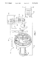
- FIG. 1 is a perspective view of the spark erosion machining device in accordance with the present invention.
- FIG. 2 is a detailed view of a portion of the spark erosion machining device of FIG. 1.
- FIG. 3 is an electrical schematic diagram of the current sensing circuit in accordance with the present invention.
- FIG. 1 is a perspective view of a SEM device 10; some components of device 10 are shown in block diagram form for purposes of clarity and explanation.
- Device 10 includes a computer numerical controlled (CNC) lathe with a CNC controller 12 and a lathe spindle 14.
- a fixture or faceplate 16 is mounted at one end of spindle 14 and includes clamping means 18 for securing a workpiece 20, such as a LPT shroud or the like, for machining.
- Device 10 further includes a wheel-shaped electrode 22 for spark erosion machining of workpiece 20.
- Electrode 22 is a soft metal, such as a soft steel, copper or the like.
- a drive motor 24 is connected to wheel-shaped electrode 22 by a drive shaft 26, such as a Setco/Klock Model No. AC200 or the like.
- Electrode 22, drive motor 24 and drive shaft 26 are held in position by a tool holder 28 which is connected to at least two axes of motion, as indicated by the X and Z axes in FIG. 1.
- Tool holder 28, the X and Z axes of motion and their respective drive mechanisms are known elements of a CNC lathe, such as a Warner and Swasey Model No. WSC18.
- the coordinate positioning of tool holder 28 and a rotational coordinate axis 29 of electrode 22 are controlled by CNC controller 12 which controls motion along the X and Z axes.
- Tool holder 28 and X and Z axes permit repositioning of electrode 22 by CNC controller 12 to control the depth of the machining cut during each machining cycle of a honeycombed shroud or similar workpiece 20 and also permit automatic in-process measurement, i.e., measurement before each subsequent machining cycle, of the highest point or radius on wheel-shaped electrode 22 for dimensional control of the machining or depth of cut of an interior portion 30 of a workpiece 20 to correct for wear of electrode 22 during the previous machining cycle.
- Wheel-shaped electrode 22 is connected by a conductor 32 or power lead to one terminal 34 of a high-current, low-voltage transformer or A.C. power supply 36.
- An oppositely polarized terminal 34' of power supply 36 is interconnected to workpiece 20 by a conductor 38 and a brush contact 40 which rides on lathe spindle 14.
- Power supply 36 is connectable to incoming line power by terminals 42 and 42'.
- a first electrical circuit is formed by power supply 36, conductor 32, wheel-shaped electrode 22, workpiece 20, faceplate 16, lathe spindle 14, brush contact 40 and conductor 38.
- Power supply 36 may be a 40 volt source which causes about 50 to about 100 amps to flow through this first electrical circuit during machining of workpiece 20.
- a cylindrically shaped gage surface 44 is concentrically mounted relative to workpiece 20 on faceplate 16 of device 10 for in-process determination of the largest radius of wheel-shaped electrode 22 to dimensionally control the machining of workpiece 20.
- Gage surface 44 may be a metallic ring which is attached to faceplate 16 by fasteners 46, such as hex head bolts or the like.
- gage surface 44 is shown mounted within the boundary of workpiece 20 in FIG. 1, in machining some components, a larger diameter gage surface may have to be mounted outside the boundary of the component.
- a current transformer 48 is magnetically coupled to conductor 32 for sensing the A.C. current flowing in conductor 32.
- Current transformer 48 is connected by terminals 50 and 50' to a current sense electronic circuit 52.
- Current sense electronic circuit 52 is in turn electrically connected to a probe input of CNC controller 12 by conductors 54 and 54'.
- workpiece 20 is rotated at a speed of about 100 to about 140 r.p.m. in one direction and wheel-shaped electrode 22 is typically rotated in an opposite direction relative to workpiece 20 at a speed of about 3,000 r.p.m. to about 4,000 r.p.m. during a machining cycle.
- the CNC controller 12 program will generate signals transmitted along signal paths 56 and 58 to cause X and Z axes of motion to wheel-shaped electrode 22 from a machining position proximate to workpiece 20, to a second position, in momentary contact with an interior portion 60 of gage surface 44.
- Electrode 22 could contact the exterior portion of gage surface 44 rather than interior portion 60 if sufficient clearance exists between workpiece 20 and gage surface 44.
- CNC controller 12 is conditioned, after a machining cycle, to bring rotating wheel-shaped electrode 22 in close proximity to gage surface 44 to cause only the highest peripheral point on electrode 22 to momentarily contact the interior of gage surface 44.
- a second electrical circuit will be formed by power supply 36, conductor 32, electrode 22, gage surface 44, faceplate 16, lathe spindle 14, brush 40 and conductor 38 when electrode 22 momentarily contacts gage surface 44.
- Current transformer 48 and current sense circuit 52 will detect a selected current level when electrode 22 contacts gage surface 44 and circuit 52 will transmit a signal to CNC controller 12.
- the signal will cause CNC controller 12 to store the coordinate position of the X axis and the Z axis of wheel-shaped electrode 22 when the electrode contacts the gage surface.
- CNC controller 12 will then calculate a new largest electrode radius from the stored X and Z axes coordinate postions of electrode 22 and from a known coordinate position of gage surface 44 which is also stored by CNC controller 12.
- Electrode 22 is then repositioned relative to workpiece 20 to correct for wearer erosion of electrode 22 caused during the previous machining cycle before a subsequent spark erosion machining operation. Electrode 22 is positioned to take the proper depth of cut in workpiece 20 during this next machining operation in response to the newly calculated electrode radius. After completing this next machining cycle, electrode 22 may again be moved into contact with gage surface 44 to calculate another new largest electrode radius and to correct for wear or erosion of electrode 22 caused by the prior machining cycle before a subsequent machining cycle. These steps may be repeated until workpiece 20 is machined to desired specifications.
- spark erosion machining may only be used to machine components which have a discontinuous surface to be machined, such as the honeycombed structural surface of the interior of a LPT shroud as shown in FIG. 2.
- the plane of rotation of electrode 22 preferably intersects the discontinuous surface being machined at a selected angle alpha, preferably about 5 to about 15 degrees relative to the surface normal of the surface being machined. Machining at angle alpha causes only an edge 62 of electrode 22 to come into contact with interior surface 60. This procedure prevents damage or burring of the honeycombed structure.
- FIG. 3 is a schematic diagram of current transformer 38 and current sense electronic circuit 52 which senses the flow of low level alternating current through conductor 32.
- the circuit will generate a monostable output pulse of a selected voltage level and a selected pulse width to signal CNC controller 12 that a gaging cycle has been completed for determination of a new largest electrode radius before a subsequent machining operation.
- the circuit 52 output pulse generated after a machining cycle and during electrode radius measurements is preferably about 12 volts and 10 milliseconds in width. This pulse is required by CNC controller 12 to detect contact between electrode 22 and gage surface 44.
- Circuit 52 should sense a low level current flow in conductor 32 to prevent gage surface 44 from being eroded during electrode radius measurements, and circuit 52 must also ignore high current flow through conductor 32 during machining of workpiece 20.
- Terminal 50' of current transformer 48 is connected to ground potential and one side of resistor 64.
- Terminal 50 of current transformer 48 is connected to the signal side of resistor 64.
- Resistor 64 is preferably about 10 ohms and converts the current sensed by transformer 48 to a voltage.
- a pair of diodes 66 and 68 are connected in parallel across resistor 64 and in opposite polarity to one another to limit the voltage across resistor 64 during a high current flow condition in conductor 32 which will occur during an actual machining operation of workpiece 20.
- Terminal 50 of transformer 48 is also connected by a resistor 70 to a noninverting input of an operational amplifier 72.
- Operational amplifier 72 may be a 748 operational amplifier as manufactured by the National Semiconductor Corporation.
- a feedback resistor 74 is connected between the output and noninverting input of op amp 72. If a 748 op amp is used, op amp 72 is preferably biased by about -12 volts and +12 volts at respective op amp contacts 4 and 7.
- a potentiometer 76 is connected to the inverting input of op amp 72. Potentiometer 76 has electrodes 78 and 78' and equal potentials of opposite polarity, preferably about +12 and -12 volts, are respectively connected to electrodes 78 and 78'.
- op amp 72 will function as a comparator with hysteresis to switch the op amp output between about +12 volts, when the current through conductor 32 is high and a machining operation is being performed, and about -12 volts, when a current of about 1/3 amp RMS or less is sensed flowing in conductor 32 during an electrode radius measurement and after a machining cycle.
- the output of operational amplifier 72 is connected to a gate contact 2 of a timer integrated circuit (I.C.) 80, such as an NE555 timer integrated circuit as manufactured by the Signetics Corporation.
- Operational amplifier 72 is connected to timer I.C. 80 by the series combination of a resistor 82 and a diode 84.
- a positive potential relative to ground is connected directly to contacts 4 and 8 of the NE555 timer and the positive potential is connected by a resistor 86 to timer contacts 6 and 7.
- Timer contact 1 is connected to ground potential and is also interconnected to timer contact 7 by a capacitor 88.
- Timer output contact 3 is connected to an opto-isolator 90 by a resistor 92.
- Opto-isolator 90 may be a TIL 157 opto-isolator as manufactured by Texas Instruments, Inc. Opto-isolator 90 prevents direct electrical contact between current sense electronic circuit 52 and the probe input of CNC controller 12 but will optically transfer a voltage pulse to CNC controller 12.
- a high current of about 10 amps to about 150 amps will be sensed by current transformer 48 and the output of operational amplifier 72 will be high or about +12 volts, if 12 volts is the biasing voltage selected for operational amplifier 72.
- the output of operational amplifier 72 will switch to +12 volts.
- the +12 volt operational amplifier output will switch to -12 volts when current flows in conductor 32 which will trigger timer I.C. 80 to output a monostable pulse having an amplitude of 12 volts for 10 milliseconds. This pulse is optically transferred to CNC controller 12 to enable the CNC to detect contact between electrode 22 and gage surface 44 and to determine a new largest electrode radius.
Landscapes
- Engineering & Computer Science (AREA)
- Mechanical Engineering (AREA)
- Physics & Mathematics (AREA)
- Thermal Sciences (AREA)
- Chemical & Material Sciences (AREA)
- Chemical Kinetics & Catalysis (AREA)
- Electrochemistry (AREA)
- Electrical Discharge Machining, Electrochemical Machining, And Combined Machining (AREA)
Abstract
Description
Claims (16)
Priority Applications (1)
| Application Number | Priority Date | Filing Date | Title |
|---|---|---|---|
| US07/660,086 US5115112A (en) | 1991-02-25 | 1991-02-25 | Spark erosion machining device and method for correcting for the wear of a machining electrode |
Applications Claiming Priority (1)
| Application Number | Priority Date | Filing Date | Title |
|---|---|---|---|
| US07/660,086 US5115112A (en) | 1991-02-25 | 1991-02-25 | Spark erosion machining device and method for correcting for the wear of a machining electrode |
Publications (1)
| Publication Number | Publication Date |
|---|---|
| US5115112A true US5115112A (en) | 1992-05-19 |
Family
ID=24648080
Family Applications (1)
| Application Number | Title | Priority Date | Filing Date |
|---|---|---|---|
| US07/660,086 Expired - Lifetime US5115112A (en) | 1991-02-25 | 1991-02-25 | Spark erosion machining device and method for correcting for the wear of a machining electrode |
Country Status (1)
| Country | Link |
|---|---|
| US (1) | US5115112A (en) |
Cited By (10)
| Publication number | Priority date | Publication date | Assignee | Title |
|---|---|---|---|---|
| US5543599A (en) * | 1994-12-14 | 1996-08-06 | Westinghouse Electric Corporation | Electron discharge machining apparatus and method |
| WO1997022783A1 (en) * | 1995-12-20 | 1997-06-26 | Abb Patent Gmbh | Guide device for a turbine with a vane support and a method of manufacturing said guide device |
| US6072143A (en) * | 1997-09-09 | 2000-06-06 | Charmilles Technologies S.A. | Measuring device and method for determining the length of an electrode |
| US20050247569A1 (en) * | 2004-05-07 | 2005-11-10 | Lamphere Michael S | Distributed arc electroerosion |
| US20070151954A1 (en) * | 2006-01-05 | 2007-07-05 | General Electric Company | Methods and apparatus for fabricating components |
| US20080142488A1 (en) * | 2006-12-19 | 2008-06-19 | General Electric Company | Compound electrode, methods of manufacture thereof and articles comprising the same |
| CN100408242C (en) * | 2005-03-08 | 2008-08-06 | 财团法人金属工业研究发展中心 | Electric discharge machining device for forming a fine conductive element |
| MD400Z (en) * | 2010-09-23 | 2012-02-29 | Институт Прикладной Физики Академии Наук Молдовы | Device for electrospark alloying (variants) |
| MD454Z (en) * | 2010-10-06 | 2012-07-31 | Институт Прикладной Физики Академии Наук Молдовы | Installation for electrospark alloying |
| EP2255912A3 (en) * | 2009-05-26 | 2013-01-02 | General Electric Company | Electric Discharge Machining Device Using Rotating Circular Blade |
Citations (9)
| Publication number | Priority date | Publication date | Assignee | Title |
|---|---|---|---|---|
| US2059236A (en) * | 1932-08-13 | 1936-11-03 | Electric Arc Cutting & Welding | Method of machining by electric current |
| US2818491A (en) * | 1955-07-13 | 1957-12-31 | Elox Corp Michigan | Electrode wear compensation |
| US3688074A (en) * | 1971-07-12 | 1972-08-29 | Jade Corp | Electrode wear compensating apparatus for an electrical discharge machine |
| US3778579A (en) * | 1972-04-27 | 1973-12-11 | Amsted Ind Inc | Arc control |
| US3816692A (en) * | 1972-03-02 | 1974-06-11 | S Ratmansky | Electrical discharge machining efficiency and safety monitoring system |
| US4039779A (en) * | 1975-12-11 | 1977-08-02 | Raycon Corporation | Apparatus for compensating for electrode wear in an electrical discharge machine |
| US4045641A (en) * | 1975-02-20 | 1977-08-30 | A.G. Fur Industrielle Elektronik Agie Losone B. Locarno | Control system for an electro-erosion machine tool |
| US4345131A (en) * | 1979-03-29 | 1982-08-17 | Ateliers Des Charmilles, S.A. | Method and apparatus for electrode tool wear compensation |
| US4948933A (en) * | 1989-02-27 | 1990-08-14 | Scan Systems, Inc. | Apparatus for cutting precision notches in work surfaces |
-
1991
- 1991-02-25 US US07/660,086 patent/US5115112A/en not_active Expired - Lifetime
Patent Citations (9)
| Publication number | Priority date | Publication date | Assignee | Title |
|---|---|---|---|---|
| US2059236A (en) * | 1932-08-13 | 1936-11-03 | Electric Arc Cutting & Welding | Method of machining by electric current |
| US2818491A (en) * | 1955-07-13 | 1957-12-31 | Elox Corp Michigan | Electrode wear compensation |
| US3688074A (en) * | 1971-07-12 | 1972-08-29 | Jade Corp | Electrode wear compensating apparatus for an electrical discharge machine |
| US3816692A (en) * | 1972-03-02 | 1974-06-11 | S Ratmansky | Electrical discharge machining efficiency and safety monitoring system |
| US3778579A (en) * | 1972-04-27 | 1973-12-11 | Amsted Ind Inc | Arc control |
| US4045641A (en) * | 1975-02-20 | 1977-08-30 | A.G. Fur Industrielle Elektronik Agie Losone B. Locarno | Control system for an electro-erosion machine tool |
| US4039779A (en) * | 1975-12-11 | 1977-08-02 | Raycon Corporation | Apparatus for compensating for electrode wear in an electrical discharge machine |
| US4345131A (en) * | 1979-03-29 | 1982-08-17 | Ateliers Des Charmilles, S.A. | Method and apparatus for electrode tool wear compensation |
| US4948933A (en) * | 1989-02-27 | 1990-08-14 | Scan Systems, Inc. | Apparatus for cutting precision notches in work surfaces |
Cited By (15)
| Publication number | Priority date | Publication date | Assignee | Title |
|---|---|---|---|---|
| US5543599A (en) * | 1994-12-14 | 1996-08-06 | Westinghouse Electric Corporation | Electron discharge machining apparatus and method |
| WO1997022783A1 (en) * | 1995-12-20 | 1997-06-26 | Abb Patent Gmbh | Guide device for a turbine with a vane support and a method of manufacturing said guide device |
| GB2314385A (en) * | 1995-12-20 | 1997-12-24 | Abb Patent Gmbh | Guide device for a turbine with a vane support and a method of manufacturing said guide device |
| GB2314385B (en) * | 1995-12-20 | 1999-09-15 | Abb Patent Gmbh | Guide device for a turbine with a guide-blade carrier and method for producing this guide device |
| US6072143A (en) * | 1997-09-09 | 2000-06-06 | Charmilles Technologies S.A. | Measuring device and method for determining the length of an electrode |
| EP1593449A3 (en) * | 2004-05-07 | 2006-01-18 | General Electric Company | Distributed arc electroerosion |
| US20050247569A1 (en) * | 2004-05-07 | 2005-11-10 | Lamphere Michael S | Distributed arc electroerosion |
| US20070256939A1 (en) * | 2004-05-07 | 2007-11-08 | General Electric Company | Methods and Apparatus for Electroerosion |
| CN100408242C (en) * | 2005-03-08 | 2008-08-06 | 财团法人金属工业研究发展中心 | Electric discharge machining device for forming a fine conductive element |
| US20070151954A1 (en) * | 2006-01-05 | 2007-07-05 | General Electric Company | Methods and apparatus for fabricating components |
| US20080142488A1 (en) * | 2006-12-19 | 2008-06-19 | General Electric Company | Compound electrode, methods of manufacture thereof and articles comprising the same |
| EP2255912A3 (en) * | 2009-05-26 | 2013-01-02 | General Electric Company | Electric Discharge Machining Device Using Rotating Circular Blade |
| RU2535820C2 (en) * | 2009-05-26 | 2014-12-20 | Дженерал Электрик Компани | Device for electric pulse machining |
| MD400Z (en) * | 2010-09-23 | 2012-02-29 | Институт Прикладной Физики Академии Наук Молдовы | Device for electrospark alloying (variants) |
| MD454Z (en) * | 2010-10-06 | 2012-07-31 | Институт Прикладной Физики Академии Наук Молдовы | Installation for electrospark alloying |
Similar Documents
| Publication | Publication Date | Title |
|---|---|---|
| CA2206718C (en) | Multi-functional measurement system | |
| US5115112A (en) | Spark erosion machining device and method for correcting for the wear of a machining electrode | |
| US4195250A (en) | Automatic measuring and tool position compensating system for a numerically controlled machine tool | |
| US4281385A (en) | Control system for a machine tool | |
| JPS6257441B2 (en) | ||
| JPS6411403B2 (en) | ||
| JPS63134150A (en) | Device for measuring selected parameter of cutting tool | |
| JPH09253979A (en) | Tool edge position measuring device | |
| EP0068643A2 (en) | Lathe tool calibrator and method | |
| JP3733538B2 (en) | Positioning device and method for electric discharge machine | |
| JPH09220685A (en) | Method for measuring material to be machined in laser beam machine | |
| JP3604473B2 (en) | Machine Tools | |
| CN207556437U (en) | A kind of camshaft signal disk angle detection mechanism | |
| JPWO1999058277A1 (en) | Positioning device and method for electric discharge machine | |
| JP3660920B2 (en) | Machine tool and processing method | |
| JPH08350B2 (en) | Origin setting method for work etc. in machine tools | |
| JPH08197384A (en) | Tip position correction device of rotating tool | |
| JPS6158263B2 (en) | ||
| JPH0655415A (en) | Measuring method for and secular change of machine tool | |
| JPH08229776A (en) | NC machine tool with tool edge position displacement measurement function | |
| EP0389639A1 (en) | Centering method in an electrolytic finishing apparatus | |
| JP3781236B2 (en) | Grinding machine and grinding method of grinding wheel position | |
| JPH07227740A (en) | Workpiece position detection method using a cutting tool | |
| JPH05345229A (en) | Three dimensional discharge machining apparatus | |
| KR890009060Y1 (en) | Tool automatic measuring device of NC lathe |
Legal Events
| Date | Code | Title | Description |
|---|---|---|---|
| AS | Assignment |
Owner name: GENERAL ELECTRIC COMPANY, A NY CORP. Free format text: ASSIGNMENT OF ASSIGNORS INTEREST.;ASSIGNORS:FITZ, III, GEORGE E.;KRENZ, RUDI O.;CARNES, HARMON R.;REEL/FRAME:005638/0730 Effective date: 19910219 |
|
| FEPP | Fee payment procedure |
Free format text: PAYOR NUMBER ASSIGNED (ORIGINAL EVENT CODE: ASPN); ENTITY STATUS OF PATENT OWNER: LARGE ENTITY |
|
| STCF | Information on status: patent grant |
Free format text: PATENTED CASE |
|
| FEPP | Fee payment procedure |
Free format text: PAYER NUMBER DE-ASSIGNED (ORIGINAL EVENT CODE: RMPN); ENTITY STATUS OF PATENT OWNER: LARGE ENTITY Free format text: PAYOR NUMBER ASSIGNED (ORIGINAL EVENT CODE: ASPN); ENTITY STATUS OF PATENT OWNER: LARGE ENTITY |
|
| FEPP | Fee payment procedure |
Free format text: PAYER NUMBER DE-ASSIGNED (ORIGINAL EVENT CODE: RMPN); ENTITY STATUS OF PATENT OWNER: LARGE ENTITY Free format text: PAYOR NUMBER ASSIGNED (ORIGINAL EVENT CODE: ASPN); ENTITY STATUS OF PATENT OWNER: LARGE ENTITY |
|
| FPAY | Fee payment |
Year of fee payment: 4 |
|
| FPAY | Fee payment |
Year of fee payment: 8 |
|
| FPAY | Fee payment |
Year of fee payment: 12 |