US5073747A - Feedback system control device and applications in amplifiers and servomechanisms - Google Patents
Feedback system control device and applications in amplifiers and servomechanisms Download PDFInfo
- Publication number
- US5073747A US5073747A US07/574,724 US57472490A US5073747A US 5073747 A US5073747 A US 5073747A US 57472490 A US57472490 A US 57472490A US 5073747 A US5073747 A US 5073747A
- Authority
- US
- United States
- Prior art keywords
- signal
- produce
- error
- phase
- amplifier
- Prior art date
- Legal status (The legal status is an assumption and is not a legal conclusion. Google has not performed a legal analysis and makes no representation as to the accuracy of the status listed.)
- Expired - Fee Related
Links
- 238000012937 correction Methods 0.000 claims abstract description 22
- 238000012986 modification Methods 0.000 claims abstract description 20
- 230000004048 modification Effects 0.000 claims abstract description 20
- 230000010363 phase shift Effects 0.000 claims abstract description 13
- 238000000034 method Methods 0.000 claims abstract description 6
- 230000008569 process Effects 0.000 claims abstract description 6
- 238000000605 extraction Methods 0.000 claims description 13
- 230000001360 synchronised effect Effects 0.000 claims description 6
- 238000012545 processing Methods 0.000 claims description 4
- 239000003990 capacitor Substances 0.000 description 3
- 238000005259 measurement Methods 0.000 description 3
- 238000001914 filtration Methods 0.000 description 2
- 230000006870 function Effects 0.000 description 2
- 230000008859 change Effects 0.000 description 1
- 230000000295 complement effect Effects 0.000 description 1
- 230000003247 decreasing effect Effects 0.000 description 1
- 230000007547 defect Effects 0.000 description 1
- 238000007599 discharging Methods 0.000 description 1
- 230000000694 effects Effects 0.000 description 1
- 230000010354 integration Effects 0.000 description 1
- 230000007246 mechanism Effects 0.000 description 1
- 230000010355 oscillation Effects 0.000 description 1
- 230000000737 periodic effect Effects 0.000 description 1
- 230000009993 protective function Effects 0.000 description 1
- 230000001052 transient effect Effects 0.000 description 1
Images
Classifications
-
- G—PHYSICS
- G05—CONTROLLING; REGULATING
- G05B—CONTROL OR REGULATING SYSTEMS IN GENERAL; FUNCTIONAL ELEMENTS OF SUCH SYSTEMS; MONITORING OR TESTING ARRANGEMENTS FOR SUCH SYSTEMS OR ELEMENTS
- G05B5/00—Anti-hunting arrangements
- G05B5/01—Anti-hunting arrangements electric
Definitions
- the present invention concerns a control device for a feedback system such as an amplifier or a servomechanism.
- Devices of this kind comprising at least one feedback loop suffer from stability defects due to phase differences introduced by the forward path and the feedback loop. This is the case with amplifiers incorporating an output transformer, for example, where oscillations can occur with a capacitive load, or with class D amplifiers whose switching mode operation entails filtering using inductors and capacitors. If the phase
- One aim of the invention is to provide a feedback system control device conferring high accuracy without compromising stability.
- the present invention consists in a feedback system control device comprising an adder adapted to produce a control signal from a feed forward signal and a correction signal, a system for processing said control signal and driving said feedback system which is adapted to produce an output signal, an error amplifier adapted to process the difference between an input signal and said output signal and to produce an error signal a four-pole network as a feed-forward circuit adapted to receive said input signal and to produce said feed forward signal, corrector adapted to produce said correction signal from said error signal said corrector comprising two processors each adapted to receive said error signal and to produce respective modification signals between which there is a relative phase shift, and a summing circuit in each processor adapted to sum said modification signals to produce said correction signal.
- the four-pole network delivers a feed forward signal identical to the input signal.
- the four-pole network is a high-pass filter.
- the corrector in the feedback system control device comprises a selective amplifier behind said error amplifier to produce said error signal, followed by said processors each receiving the error signal and generating modification signals with a phase shift between them and an adder summing the two modification signals to deliver the correction signal.
- At least one of the processors in the feedback system control device includes a phase-shifter which receives the feed forward signal and produces a phase-shifted signal, an error extractor which receives this phaseshifted signal and the error signal and produces an extraction signal and an amplifier receiving this extraction signal followed by a multiplier forming the product of this phase-shifted signal and the output signal of the amplifier and supplying the modification signal.
- At least one of the processors in the feedback system control device includes a phase-shifter which receives the input signal and produces a phase-shifted signal, an error extractor which receives this phase-shifted signal and the error signal and produces an extraction signal and an amplifier receiving this extraction signal followed by a multiplier producing the product of this phase-shifted signal and the output signal of the amplifier and supplying the modification signal.
- the error extractor is an analog multiplier, the extraction signal being the product of the phase-shifted signal and the error signal.
- the error extractor comprises a signal shaper which receives the phase-shifted signal to produce a squarewave signal and a synchronous detector whose logic input is the squarewave signal and whose analog input is the error signal from which the extraction signal is produced.
- the amplifier of at least one processor of the feedback system control device is advantageously an integrator.
- the amplifier of at least one processor comprises a low-pass filter followed by an amplifier.
- the multiplier comprises a chopper and a low-pass filter.
- both processors in the feedback system control device include a phase-shifter, the phase shifts generated by the two phase-shifters being different.
- one processor in the feedback system control device has no phase-shifter and the other applies a phase-shift of 90°.
- the invention finds applications in controlling an amplifier or a servomechanism, for example.
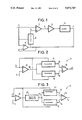
- FIG. 1 is a block schematic of a feedback system control device in accordance with the invention.
- FIG. 2 shows a corrector
- FIG. 3 shows an alternate corrector
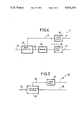
- FIG. 4 shows a processor
- FIG. 5 shows one embodiment of an error extractor.
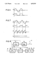
- FIG. 6 shows the functioning of a signal shaper.
- FIG. 7 shows the functioning of a synchronous detector.
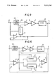
- FIG. 8 shows an alternate processor
- FIG. 9 shows one embodiment of a feedback system
- FIG. 10 shows a second embodiment of a feedback system control device.
- Entities included in more than one drawing always have the same reference number.
- the control device in accordance with the invention shown in FIG. 1 includes an adder 1 which produces a control signal 2 from an input magnitude 3 and a correction signal 4. The control signal is then fed to an amplifier 5 whose output drives the system 6 to be controlled. This system delivers control information in the form of an output signal 7.
- the correction signal 4 is produced in a corrector 8 which receives an error signal 10 produced by an error amplifier 8 combines the input signal and the output signal.
- the error amplifier 9 produces the error signal 10 which represents the difference between the input signal 3 and the output signal 7.
- This error signal drives two processors 11, 12 which produce modification signals 13, 14. These two modification signals are then added in a summing circuit 15 the output signal of which is the correction signal 4.
- An alternative corrector 8 shown in FIG. 3 also includes a frequency-selective amplifier 20 which receives the output signal from the error amplifier 9 and produces the error signal 10. This frequency-selective amplifier is tuned to the fundamental frequency of the input signal 3 and rejects harmonic frequencies present at the output of the error amplifier 9.
- the processor shown in FIG. 4 includes a phaseshifter 16 which receives the input signal 3 and delivers a phase-shifted signal to an error extractor 20.
- the error extractor also receives the error signal 10 and in a first embodiment is an analog multiplier which forms the product of the two signals applied to its inputs; it delivers an extraction signal 29.
- the error extractor 20 includes a signal shaper 31 which produces from a periodic signal 18 a squarewave logic signal 19 with the same period, shown in FIG. 6. This squarewave signal is fed to the logic input of a synchronous detector 33. The function of this detector is symbolically represented in FIG. 7.
- the detector has a logic input and an analog input and delivers at its output the signal 22 applied to the analog input if the logic input 23 is activated or the complement of the signal 22 if this input is not activated.
- the average value 24 of the output signal 21 if the input signal 22 is sinusoidal and if the signal applied to the logic input is at the same frequency is therefore proportional to the cosine of the phase-shift between these two signals.
- the error signal 10 is applied to the analog input of the synchronous detector 33, the output from this detector being fed to an amplifier 25.
- this amplifier is an integrator. In another embodiment it is a high-gain amplifier and includes a low-pass filter. In both cases the time constants are chosen to be very much greater than the period of the input signal 3.
- this processor includes a multiplier 26 which forms the product of the phase-shifted signal 18 from the phase-shifter 16 and the output signal from the amplifier 25; the result is a modification signal 13, 14.
- the multiplier is replaced by a chopper.
- the dashed line between the phase-shifter 16 and the error extractor 30 represents the case where the latter is an analog multiplier, the full line linking the signal shaper 31 to the error extractor representing the case where the latter is a synchronous detector.
- the chopper includes an analog switch 27 which has a logic input and an analog input and which transfers to its output the signal applied to its analog input if its logic input is activated or nothing otherwise.
- the output signal from the amplifier 25 is applied to the analog input and the output signal from the signal shaper 17 is fed to its logic input.
- a low-pass filter 28 is provided at the output of this analog switch 27 to eliminate the DC component and the harmonic frequencies and retain only the fundamental frequency of the output signal from the signal shaper 31.
- the first processor is as described above and its phase-shifter introduces a phase-shift of 90°, for example, the second processor being identical except that it does not include any phase-shifter. More generally, use may be made of two processors each including a phase-shifter, producing different phase-shifts.
- control device can apply vector correction by adding to the input signal 3 two modification signals 13, 14 which operate on the phase and the amplitude of the control signal 2.
- the adders 1 and 15 are shown as two separate units to clarify the explanation but can obviously be combined into a single unit with three inputs.
- each processor the voltage at the output of the amplifier 25 varies with the error signal. This voltage is applied to the multiplier 26 to correct the input signal, reducing the magnitude of the error signal. If the amplifier 25 is an integrator its output moves more and more slowly towards an equilibrium value representing a null error. If the amplifier includes a low-pass filter the error is not eliminated but proportional to the reciprocal of the gain of the amplifier, which can be chosen to be sufficiently high for the error to be within the specifications of the device.
- the processor reacts in the way described above.
- the sensitive element of the control device is the amplifier 9. It is the accuracy of this component which determines the accuracy of the control device as the errors due to the other components, especially the multipliers and the phaseshifters, are compensated by the loop. In particular, phase rotations caused by the frequency-selective amplifier 20 have no effect.
- the system 6 may be a servo mechanism or a servo amplifiers, in particular amplifiers used to protect and monitor electrical power distribution networks.
- Amplifiers of this kind have a very high power gain and amplify a signal of a few mW produced by capacitive dividers to a level of 50 or 100 VA. They have a protective function and must therefore combine 3% accuracy with high speed. They also have a measurement function which requires 0.2% accuracy over a long integration period.
- the device will also find applications in control systems such as servomechanisms.
- This device further comprises a feed forward circuit 37, e.g. a four-pole network such as a filter which receives the input signal 3.
- a feed forward circuit 37 e.g. a four-pole network such as a filter which receives the input signal 3.
- this filter produces an output signal which is applied to the adder 1 in place of the input signal 3.
- the output signal from the filter 37 is applied to the adder 1 as previously, but it is additionally applied to the input of the phase-shifters 16 of both processors 11, 12 in place of the input signal 3.
- the filter 37 is a high-pass filter, for example, and eliminates unwanted DC or aperiodic components that may be present in the input signal 3 under transient conditions.
- the output signal of the divider constitutes the input signal 3 of the control device and may include such unwanted components.
- the line has a very high time constant when it is open-circuit, especially after a circuit-breaker trips out. If the device is re-engaged in a time which is short in relation to this time constant, the capacitor of the capacitive divider, which receives a voltage equal to the high-tension voltage less the measurement voltage, will not be discharged and the output signal from this divider will be the sum of the measurement signal itself and a spurious signal with exponentially decreasing amplitude typical of the discharging of a capacitor.
- the filter 37 enables this spurious signal and all its attendant disadvantages to be eliminated.
Landscapes
- Physics & Mathematics (AREA)
- General Physics & Mathematics (AREA)
- Engineering & Computer Science (AREA)
- Automation & Control Theory (AREA)
- Feedback Control In General (AREA)
- Amplifiers (AREA)
- Control Of Position Or Direction (AREA)
- Numerical Control (AREA)
- Steering Control In Accordance With Driving Conditions (AREA)
- Electrotherapy Devices (AREA)
Applications Claiming Priority (2)
| Application Number | Priority Date | Filing Date | Title |
|---|---|---|---|
| FR8911386A FR2651339B1 (fr) | 1989-08-30 | 1989-08-30 | Dispositif d'asservissement d'un systeme a contre-reaction et application aux amplificateurs et servomecanismes. |
| FR8911386 | 1989-08-30 |
Publications (1)
| Publication Number | Publication Date |
|---|---|
| US5073747A true US5073747A (en) | 1991-12-17 |
Family
ID=9384997
Family Applications (1)
| Application Number | Title | Priority Date | Filing Date |
|---|---|---|---|
| US07/574,724 Expired - Fee Related US5073747A (en) | 1989-08-30 | 1990-08-30 | Feedback system control device and applications in amplifiers and servomechanisms |
Country Status (10)
| Country | Link |
|---|---|
| US (1) | US5073747A (ja) |
| EP (1) | EP0415313B1 (ja) |
| JP (1) | JPH0833760B2 (ja) |
| CN (1) | CN1030013C (ja) |
| AT (1) | ATE131944T1 (ja) |
| BR (1) | BR9004260A (ja) |
| CA (1) | CA2024199C (ja) |
| DE (1) | DE69024285T2 (ja) |
| ES (1) | ES2081330T3 (ja) |
| FR (1) | FR2651339B1 (ja) |
Cited By (7)
| Publication number | Priority date | Publication date | Assignee | Title |
|---|---|---|---|---|
| US5272423A (en) * | 1991-01-26 | 1993-12-21 | Samsung Electronics Co., Ltd. | Velocity control method for a synchronous AC servo motor |
| US5311110A (en) * | 1990-11-08 | 1994-05-10 | Fanuc Ltd. | Feedforward control method for servomotors |
| US5448145A (en) * | 1991-09-09 | 1995-09-05 | Fanuc Ltd. | Feedforward control method for a servomotor |
| US6052252A (en) * | 1996-04-30 | 2000-04-18 | Samsung Electronics Co., Ltd. | Adaptive feed forward device for reducing current control errors |
| US20050285558A1 (en) * | 2004-05-14 | 2005-12-29 | David Watt | Adaptive command filtering for servomechanism control systems |
| US20070085505A1 (en) * | 2005-09-30 | 2007-04-19 | Brother Kogyo Kabushiki Kaisha | Drive control apparatus |
| US20080200998A1 (en) * | 2007-02-15 | 2008-08-21 | Asml Netherlands B.V. | Lithographic apparatus and device manufacturing method |
Families Citing this family (5)
| Publication number | Priority date | Publication date | Assignee | Title |
|---|---|---|---|---|
| FR2720223B1 (fr) * | 1994-05-25 | 1996-08-30 | Jackie Jumelle | Dispositif empêchant les taupes de remonter à la surface du sol et procédé pour l'installation de ce dispositif. |
| FR2720511B1 (fr) * | 1994-05-25 | 1996-07-05 | Gec Alsthom T & D Sa | Procédé et dispositif pour la suppression d'une composante perturbatrice d'un signal périodique et application à un transformateur capacitif électronique de tension. |
| FR2724242B1 (fr) * | 1994-09-05 | 1997-01-10 | Gec Alsthom T & D Sa | Procede d'auto-etalonnage d'un systeme asservi et systeme etalonne par le procede |
| CN101228690B (zh) * | 2005-07-29 | 2010-08-18 | 富士通株式会社 | 延迟调整装置 |
| CN101227172B (zh) * | 2007-01-15 | 2012-05-30 | 昆山杰得微电子有限公司 | 一种模拟d类放大器 |
Citations (6)
| Publication number | Priority date | Publication date | Assignee | Title |
|---|---|---|---|---|
| GB2013374A (en) * | 1978-01-31 | 1979-08-08 | Nippon Telegraph & Telephone | Servo systems |
| US4341986A (en) * | 1981-01-22 | 1982-07-27 | The United States Of America As Represented By The Secretary Of The Navy | Servo control system for the positioning of an apparatus |
| EP0180292A1 (en) * | 1984-10-03 | 1986-05-07 | Kabushiki Kaisha Toshiba | Process control apparatus |
| US4885676A (en) * | 1988-03-09 | 1989-12-05 | Storage Technology Corporation | Control loop instability detection and correction apparatus |
| US4904912A (en) * | 1987-10-09 | 1990-02-27 | Nobuo Yamamoto | Control mechanism employing internal model coordination feedforward method |
| US4914365A (en) * | 1987-10-09 | 1990-04-03 | Kabushiki Kaisha Toshiba | Control device for servo motor |
Family Cites Families (2)
| Publication number | Priority date | Publication date | Assignee | Title |
|---|---|---|---|---|
| SE427508B (sv) * | 1981-08-24 | 1983-04-11 | Naf Ab | Forfarande for instellning av en pid-regulator for en process |
| JPS58169202A (ja) * | 1982-03-31 | 1983-10-05 | Yamatake Honeywell Co Ltd | プロセス制御装置 |
-
1989
- 1989-08-30 FR FR8911386A patent/FR2651339B1/fr not_active Expired - Lifetime
-
1990
- 1990-08-27 EP EP90116374A patent/EP0415313B1/fr not_active Expired - Lifetime
- 1990-08-27 DE DE69024285T patent/DE69024285T2/de not_active Expired - Fee Related
- 1990-08-27 AT AT90116374T patent/ATE131944T1/de not_active IP Right Cessation
- 1990-08-27 ES ES90116374T patent/ES2081330T3/es not_active Expired - Lifetime
- 1990-08-28 JP JP2226444A patent/JPH0833760B2/ja not_active Expired - Lifetime
- 1990-08-29 BR BR909004260A patent/BR9004260A/pt not_active IP Right Cessation
- 1990-08-29 CN CN90108172A patent/CN1030013C/zh not_active Expired - Fee Related
- 1990-08-29 CA CA002024199A patent/CA2024199C/fr not_active Expired - Fee Related
- 1990-08-30 US US07/574,724 patent/US5073747A/en not_active Expired - Fee Related
Patent Citations (6)
| Publication number | Priority date | Publication date | Assignee | Title |
|---|---|---|---|---|
| GB2013374A (en) * | 1978-01-31 | 1979-08-08 | Nippon Telegraph & Telephone | Servo systems |
| US4341986A (en) * | 1981-01-22 | 1982-07-27 | The United States Of America As Represented By The Secretary Of The Navy | Servo control system for the positioning of an apparatus |
| EP0180292A1 (en) * | 1984-10-03 | 1986-05-07 | Kabushiki Kaisha Toshiba | Process control apparatus |
| US4904912A (en) * | 1987-10-09 | 1990-02-27 | Nobuo Yamamoto | Control mechanism employing internal model coordination feedforward method |
| US4914365A (en) * | 1987-10-09 | 1990-04-03 | Kabushiki Kaisha Toshiba | Control device for servo motor |
| US4885676A (en) * | 1988-03-09 | 1989-12-05 | Storage Technology Corporation | Control loop instability detection and correction apparatus |
Non-Patent Citations (2)
| Title |
|---|
| Patent Abstracts of Japan, vol. 8, No. 6 (P 247) 1443 , Jan. 12, 1984; & JP A 58 169 202 (Yamatake Honeywell K.K.), 10/5/1983. * |
| Patent Abstracts of Japan, vol. 8, No. 6 (P-247)[1443], Jan. 12, 1984; & JP-A-58 169 202 (Yamatake Honeywell K.K.), 10/5/1983. |
Cited By (10)
| Publication number | Priority date | Publication date | Assignee | Title |
|---|---|---|---|---|
| US5311110A (en) * | 1990-11-08 | 1994-05-10 | Fanuc Ltd. | Feedforward control method for servomotors |
| US5272423A (en) * | 1991-01-26 | 1993-12-21 | Samsung Electronics Co., Ltd. | Velocity control method for a synchronous AC servo motor |
| US5448145A (en) * | 1991-09-09 | 1995-09-05 | Fanuc Ltd. | Feedforward control method for a servomotor |
| US6052252A (en) * | 1996-04-30 | 2000-04-18 | Samsung Electronics Co., Ltd. | Adaptive feed forward device for reducing current control errors |
| US20050285558A1 (en) * | 2004-05-14 | 2005-12-29 | David Watt | Adaptive command filtering for servomechanism control systems |
| US7345448B2 (en) * | 2004-05-14 | 2008-03-18 | Electro Scientific Industries, Inc. | Adaptive command filtering for servomechanism control systems |
| US20070085505A1 (en) * | 2005-09-30 | 2007-04-19 | Brother Kogyo Kabushiki Kaisha | Drive control apparatus |
| US7498760B2 (en) * | 2005-09-30 | 2009-03-03 | Brother Kogyo Kabushiki Kaisha | Drive control apparatus |
| US20080200998A1 (en) * | 2007-02-15 | 2008-08-21 | Asml Netherlands B.V. | Lithographic apparatus and device manufacturing method |
| US8014881B2 (en) * | 2007-02-15 | 2011-09-06 | Asml Netherlands B.V. | Lithographic apparatus and device manufacturing method |
Also Published As
| Publication number | Publication date |
|---|---|
| FR2651339B1 (fr) | 1991-10-04 |
| FR2651339A1 (fr) | 1991-03-01 |
| DE69024285D1 (de) | 1996-02-01 |
| CN1050622A (zh) | 1991-04-10 |
| BR9004260A (pt) | 1991-09-03 |
| EP0415313A1 (fr) | 1991-03-06 |
| CA2024199C (fr) | 1993-07-27 |
| CA2024199A1 (fr) | 1991-03-01 |
| DE69024285T2 (de) | 1996-05-15 |
| CN1030013C (zh) | 1995-10-11 |
| JPH03119402A (ja) | 1991-05-21 |
| ES2081330T3 (es) | 1996-03-01 |
| EP0415313B1 (fr) | 1995-12-20 |
| ATE131944T1 (de) | 1996-01-15 |
| JPH0833760B2 (ja) | 1996-03-29 |
Similar Documents
| Publication | Publication Date | Title |
|---|---|---|
| US5073747A (en) | Feedback system control device and applications in amplifiers and servomechanisms | |
| EP0526557B1 (en) | Apparatus and method for reducing distortion in amplification | |
| US4292580A (en) | Circuit arrangement for attenuation of power oscillations in networks | |
| US5334946A (en) | Apparatus and method for reducing distortion in amplification | |
| JPH10163811A (ja) | 直交2軸信号用フィルタ回路 | |
| US6212540B1 (en) | Filter circuit | |
| EP0259805B1 (en) | Reactive power compensation apparatus | |
| JPH1117757A (ja) | 90度移相回路 | |
| US6005419A (en) | Apparatus and method for harmonic reduction in a direct digital synthesizer | |
| EP0478071B1 (en) | Analogue-to-digital converter | |
| US4958114A (en) | Feedback controller | |
| US4862106A (en) | Signal generating apparatus using PLL circuit | |
| FI70334B (fi) | Pulsbreddmultiplikator | |
| SU1229921A1 (ru) | Способ управлени двум статическими преобразовател ми частоты,работающими параллельно на общую нагрузку | |
| GB2254505A (en) | Freqency reduction for input to processor used in feedforward distortion correction | |
| US4906912A (en) | Apparatus for controlling the load angle of a converter | |
| JPH01292405A (ja) | ディジタル位置サーボ装置 | |
| JPS6233834B2 (ja) | ||
| JPS6247214A (ja) | デジタル・アナログ変換回路 | |
| SU1166300A1 (ru) | Устройство автоматической подстройки частоты | |
| Brennan | RF beam control for the AGS booster | |
| JPS5850444B2 (ja) | 自動平衡増幅回路 | |
| US3488598A (en) | Closed loop control system employing a-c amplification of d-c error correcting signals | |
| SU935978A1 (ru) | Генератор синусоидальных колебаний | |
| KR19990086187A (ko) | 디지털 전류 피드포워드 제어 시스템 |
Legal Events
| Date | Code | Title | Description |
|---|---|---|---|
| AS | Assignment |
Owner name: GEC ALSTHOM SA, FRANCE Free format text: ASSIGNMENT OF ASSIGNORS INTEREST.;ASSIGNORS:DUPRAZ, JEAN-PIERRE;MONCORGE, JEAN-PAUL;REEL/FRAME:005756/0317 Effective date: 19900731 |
|
| FEPP | Fee payment procedure |
Free format text: PAYOR NUMBER ASSIGNED (ORIGINAL EVENT CODE: ASPN); ENTITY STATUS OF PATENT OWNER: LARGE ENTITY |
|
| FPAY | Fee payment |
Year of fee payment: 4 |
|
| FEPP | Fee payment procedure |
Free format text: PAYER NUMBER DE-ASSIGNED (ORIGINAL EVENT CODE: RMPN); ENTITY STATUS OF PATENT OWNER: LARGE ENTITY Free format text: PAYOR NUMBER ASSIGNED (ORIGINAL EVENT CODE: ASPN); ENTITY STATUS OF PATENT OWNER: LARGE ENTITY |
|
| FPAY | Fee payment |
Year of fee payment: 8 |
|
| REMI | Maintenance fee reminder mailed | ||
| LAPS | Lapse for failure to pay maintenance fees | ||
| STCH | Information on status: patent discontinuation |
Free format text: PATENT EXPIRED DUE TO NONPAYMENT OF MAINTENANCE FEES UNDER 37 CFR 1.362 |
|
| FP | Lapsed due to failure to pay maintenance fee |
Effective date: 20031217 |