US5015081A - Binocular microscope - Google Patents
Binocular microscope Download PDFInfo
- Publication number
- US5015081A US5015081A US07/449,052 US44905289A US5015081A US 5015081 A US5015081 A US 5015081A US 44905289 A US44905289 A US 44905289A US 5015081 A US5015081 A US 5015081A
- Authority
- US
- United States
- Prior art keywords
- housing portion
- pupil
- movable housing
- rays
- stationary housing
- Prior art date
- Legal status (The legal status is an assumption and is not a legal conclusion. Google has not performed a legal analysis and makes no representation as to the accuracy of the status listed.)
- Expired - Lifetime
Links
Images


Classifications
-
- G—PHYSICS
- G02—OPTICS
- G02B—OPTICAL ELEMENTS, SYSTEMS OR APPARATUS
- G02B21/00—Microscopes
- G02B21/18—Arrangements with more than one light path, e.g. for comparing two specimens
- G02B21/20—Binocular arrangements
Definitions
- This invention relates to a binocular microscope in which the observing direction by an observer (hereinafter simply referred to as the "observing direction”) can be changed.
- the conventional operation microscope comprises a leg portion, a supporting post secured to the leg portion, a universal arm portion for vertically reciprocally moving the supporting post, and a mirror portion comprising a microscope and an illuminating device which are mounted on the foremost end of the universal arm.
- the mirror portion is rotatably mounted on the universal arm portion. Therefore, when the observer wants to change the observing direction, the whole mirror portion is rotated with respect to the universal arm.
- a microscope for the use of an assistant (hereinafter simply referred to as the "assistant microscope”) is rotatably mounted on a lens-barrel portion of a microscope for the use of an operator (hereinafter simply referred to as the "operator microscope”).
- the assistant microscope mounted on the lens-barrel of the operator microscope is employed, the operator and the assistant may interfere with each other. Therefore, the mounting position of the assistant microscope must be changed as such that the operator can carry out his operating work without interference.
- an operation microscope in which an assistant microscope receives a part of a beam of rays coming from an objective lens of an operator microscope through an optical member such as a half mirror, so that the view axis of the assistant microscope will be in alignment with that of the operator microscope.
- Another object of the present invention is to provide a binocular microscope in which a bright and stereoscopic observing image can be obtained even when the observing direction of the observer is changed.
- the feature of the present invention is in that an objective optical system is stored in a stationary housing portion;
- a relay optical system and an ocular optical system are stored in a movable housing portion disposed on the stationary housing portion;
- Another feature of the present invention is that the radius of an outgoing pupil of a stationary housing portion is larger than that of an incident pupil of a movable housing portion so that a large portion of the light rays passing through the incident pupil of the movable housing portion, which forms the image within a movable range of the movable housing, will pass through the outgoing pupil of the stationary housing portion.
- a further feature of the present invention is that the radius of a movable housing is larger than that of a stationary housing portion so that a large portion of the light rays passing through an outgoing pupil of the stationary housing, which light rays contribute to form an image within a movable range of the movable housing portion, will pass through an incident pupil of the movable housing portion.
- a still further feature of the present invention is that an outgoing pupil of a stationary housing portion and an incident pupil of a movable housing portion are spaced from one another.
- a further feature of the present invention is that the movable range of a movable housing portion is limited such that a large portion of the light rays passing through an outgoing pupil of a stationary housing portion will pass through an incident pupil of the movable housing portion.
- an objective optical system includes a variable power optical system, and an outgoing pupil of a stationary housing portion and an incident pupil of a movable housing portion are configured such that a large portion of the light rays passing through the outgoing pupil which contribute to forming an image will enter the incident pupil at any power.
- FIG. 1 is a schematic view showing the configuration of a binocular microscope in which the present invention is incorporated;
- FIG. 2 is a schematic view showing a part of the configuration of the binocular microscope of FIG. 1 direction;
- FIG. 3 is a schematic view showing the arrangement of optical systems of an objective optical system in the binocular microscope of FIG. 1 but when viewed from the above;
- FIGS. 4(a)-4(b) are schematic illustrations showing a variation in power in an optical system.
- FIGS. 5(a)-5(c) illustrate the state of a beam of rays and corresponding observing images when a movable housing is not rotated, with respect to a stationary housing;
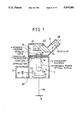
- FIGS. 7(a)-7(b) is an illustration showing the state of beam of a rays and observing images when a movable housing is rotated with respect to a stationary housing about a rotating plane positioned on the outlet side of the relays lens;
- FIGS. 8(a)-8(d) illustrate the state of beam of a rays when an outgoing pupil E at the side of a stationary housing is larger than an incident pupil E' at the side of a movable housing and when the outgoing pupil E is spaced from the incident pupil E';
- FIGS. 9(a)-9(d) illustrate the state of beam a rays when an outgoing pupil at the side of a stationary housing is larger than an incident pupil E' at the side of a movable housing and when the outgoing pupil E is proximate to the incident pupil E';
- FIGS. 10(a)-10(d) illustrate the state of beam of a rays when an incident pupil E' at the side of a movable housing is larger than an outgoing pupil E at the side of a stationary housing and when the incident pupil is spaced from the incident pupil;
- FIGS. 11(a)-11(d) illustrate state of beam of a rays when an incident pupil E' at the side of a movable housing is larger than an outgoing pupil E at the side of a stationary housing and when the incident pupil is proximate to the outgoing pupil;
- FIGS. 12(a)-12(d) illustrate the state of beam of a rays when an incident pupil E' at the side of a movable housing is generally the same in size as an incident pupil E at the side of a stationary housing and when the incident pupil is proximate to the outgoing pupil.
- a box-like body of a binocular microscope 1 comprises a stationary housing 2 and a movable housing 4 rotatably disposed on an upper surface of the stationary housing.
- the stationary housing 2 is provided therein with an objective optical system T.
- the objective optical system T comprises an objective lens 10 and a pair of variable power optical systems 12 for the use of both right and left eyes and a pair of stationary housing aperture diaphragms 14.
- An illuminating light source 30 is disposed within a casing C which is disposed at the outside of the stationary housing 2. Illuminating light emitted by the illuminating light source 30 is introduced into the stationary housing 2 through an aperture 2a which is formed in the stationary housing 2.
- An illuminating prism 32 is disposed within the stationary housing 2. The illuminating prism 32 is adapted to guide the illuminating light, which has been introduced into the stationary housing 2, to an object 6 through the objective lens 10 so that the illuminating light will illuminate the object.
- the objective lens 10, the illuminating prism 32, the stationary housing aperture diaphragms 14, etc. are secured to the interior of the stationary housing 2 by a supporting member not illustrated.
- the variable power optical system 12 is held within the stationary housing 2 by a holding member "not illustrated” such that the system 12 can rotate about a rotating axis 12a which is perpendicular to an optical axis 34.
- the binocular microscope 1 is designed as such that the object 6 can be stereoscopically observed through the pair of oculars 26 along a pair of optical axes 34 which are disposed at predetermined angles.
- the movable housing 4 is rotatably mounted on the stationary housing 2 as such that the housing 4 can rotate about a center line 36 disposed between the optical axes 34' of the right and left optical systems.
- the stationary housing 2 is provided at its upper surface with a guiding member of an arcuate shape encircled about the center line 36 and at its bottom surface with an engaging portion for engaging with the guiding member.
- the guiding member and the engaging portion serve as moving means.
- the stationary housing 2 is formed at its upper surface with a recess 9 and at its bottom surface with a projection 8 for engaging in the recess 8. Due to the foregoing arrangement, the rotating range of the movable housing 4 is restricted.
- variable power lens systems 12 are rotatable about the rotating axis 12a which is perpendicular to the optical axes 34' and that if it is rotated by 180° from the illustrated state, the power for observation is varied.
- FIGS. 4(a)-4(b) illustrates the state of a beam of rays when the power has been varied.
- the movable housing aperture diaphragm 16 is coincident with the incident pupil E' and the stationary housing aperture diaphragm 14 is coincident with the outgoing pupil E of the stationary housing 2.
- variable power optical system 12 If the variable power optical system 12 is rotated by 180° here, it is brought to be in the state as shown in FIG. 4(b) where the power is high.
- variable power optical system 12 and the relay lenses 18 are formed by the afocal optical system will be explained with reference to FIGS. 5 through 7.
- FIGS. 5(a)-5(c) illustrate the states where the movable housing 4 is not rotated with respect to the stationary housing 2.
- FIG. 5(a) shows the positions of the relay lenses 18 of the movable housing 4
- FIG. 5(b) shows the state of beam of rays from the relay lenses 18 to the imaging position at this time
- FIG. 5(c) shows images which can be observed through the oculars 26.
- 50 denotes a view field diaphragm
- 51 denotes an outgoing pupil at the side of the stationary housing.
- the beam of rays are in the form of a parallel pencil of rays at the object side (left side in the figure) of the relay lens 18, and a variable power lens system "not illustrated" and an afocal optical system are formed.
- the beam of rays become a converging beam of rays at the image side (right side in the figure) of the relay lens 18, thereby to form images A' and O'.
- FIG. 6(a) shows the position where the relay lenses 18 of the movable housing 4 are rotated
- FIG. 6(b) shows the position of a rotating plane 52 at this time and the state of the beam of rays from the relay lens 18 to the positions of the images
- FIG. 6(c) shows images which can be observed through the oculars 26.
- FIGS. 6(b) and 6(c) even when the movable housing 4 is rotated and the position of the relay lens 18 is moved with respect to the stationary housing 2, the extension of the beam of rays passing through the center of the relay lens 18 become the optical axis and also become the view field center O.
- the positions of the observing images are rotated by generally equal amounts about the view field center O by the right and left oculars due to the rotation of the movable housing (see FIG. 6(c)), and the state of the stereoscopic view is not jeopardized.
- FIGS. 7(a)-7(d) illustrate the state where the movable housing 4 is rotated by serving the position at the image side of the relay lens 18 as a rotating plane 52'.
- FIG. 7(a) shows the position of the rotating plane 52' and the state of a beam of rays from the relay lens 18 to the imaging position
- FIG. 7(b) shows an observing image through the oculars 26.
- the observation in this case accompanies the rotation about the center O as well as a parallel movement in the right and left opposite directions.
- FIGS. 8(a)-8(d), 9(a)-9(d), 10(a)-10(d), 11(a)-11(d), and 12(a)-12(d) in which show the state of a beam of rays on the incident plane E' at the side of the movable housing 4 before and after rotation of the movable housing 4, and the state of a beam of rays from the outgoing pupil E at the side of the stationary housing 2 and the incident pupil E' at the side of the movable housing 4 before and after rotation of the movable housing 4 to the images A' and O'.
- FIGS. 8(a)-(d) shows a case where the outgoing pupil E is larger than the incident pupil E' and the outgoing pupil is spaced from the incident pupil.
- FIGS. 8(a) and 8(b) show the state of a beam of rays before the rotation of the movable housing 4.
- the beam of rays passing through the incident pupil E' of a comparatively small diameter is included in the outgoing pupil E and forms images O' and A'.
- FIGS. 8(c) and (d) show the state of beam of rays after the rotation of the movable housing 4.
- the beam of rays (the beam of rays shown by the broken line in the figures) which passes through the incident pupil E' to contribute in forming an image at the point A', as well as the beam of rays (the beam of rays shown by the solid line in the figures) which contributes in forming an image at the point O', are included in the outgoing pupil E, there can be obtained an image as bright as the observing image before the rotation of the movable housing 4, and the image will not become dark due to the rotation of the movable housing 4. The same is true when the movable housing 4 is rotated counter-clockwise.
- FIGS. 9(a)-(d) shows a case which is the same as FIGS. 8(a)-(d) in the respect that the outgoing pupil E is larger than the incident pupil E' but which is different in that the outgoing pupil is formed proximate to the incident pupil. Therefore, although the state of a beam of rays is in the same relation as that of FIGS. 8(a)-(d), there can be obtained an image as bright as an observing image before the rotation of the movable housing 4 even after the rotation of the movable housing 4, even if the outgoing pupil is relatively small.
- FIGS. 10(a)-(d) show a case in which the incident pupil E' is larger than the outgoing pupil E and the outgoing pupil E is spaced away from the incident pupil E'.
- FIGS. 10(a) and (b) show the state of a beam of rays before the rotation of the movable housing 4.
- the solid line P 1 shows the beam of rays converging to the point O'
- the broken line P 2 shows the beam of rays converging to the point A'.
- the beam of rays passing through the outgoing pupil E of a small diameter is included in the incident pupil E' and forms images O' and A'.
- FIGS. 10(c) and (d) show the state of beam of rays after the rotation of the movable housing 4.
- the movable housing 4 is rotated clockwise as shown in FIG. 10(c)
- the beam of rays (the beam of rays shown by the broken line P 2 in the figure) which passes the outgoing pupil E to contribute in forming an image at the point A', as well as the beam of rays (the beam of rays shown by the solid line P 1 in the figure) which contributes in forming an image at the point O', are included in the incident pupil E, there can be obtained an image as bright as an observing image before the rotation of the movable housing 4, and the image will not become dark due to the rotation of the movable housing 4.
- the movable housing 4 is rotated counter-clockwise.
- FIGS. 11(a)-(d) show a case which is the same as that of FIGS. 10(a)-(d) in the respect that the outgoing pupil E is smaller than the incident pupil E' but which is different in that the outgoing pupil is formed proximate to the incident pupil. Therefore, although the state of the beam of rays is in the relation similar to that of FIGS. 10(a)-(d), there can be obtained an image as bright as an observing image before the rotation of the movable housing 4 even after the rotation of the movable housing 4, even if the incident pupil is comparatively small.
- FIGS. 12(a)-12(d) show a case which is suitable when the angle of rotation of the movable housing is small and in which the outgoing pupil E and the incident pupil E' are generally in the same size and generally in the same position.
- FIGS. 12(a) and 12(b) show the state of beam of rays before the rotation of the movable housing, and the significance of the beam of rays shown by the broken line and the beam of rays shown by the solid line is generally the same as that of FIG. 8. Therefore, the beams of rays, which have passed through the outgoing pupil and the incident pupil, contribute in forming images as shown in the figures.
- FIGS. 12(c) and 12(d) show the state of a beam of rays after the rotation of the movable housing 4.
- the beam of rays which contributes in forming an image after the rotation of the movable housing is that which passes through both the outgoing pupil at the side of the stationary housing and the incident pupil at the side of the movable housing as shown in the figures, and the amount thereof is reduced as the movable housing is rotated further.
- the means for moving the movable housing is rotatable about the center line which is parallel with the optical axis of the variable power optical system
- the present invention is not limited to this embodiment.
- the present invention is likewise applicable even if the movable housing is linearly moved but within a plane perpendicular to the optical axis.
- an image will not become darker even if the observing direction is varied by moving the movable housing, and there can be obtained an image which can be stereoscopically observed.
- the present invention is to be applied to a binocular microscope having the afore-mentioned variable power optical system, if it is constituted as such that the outgoing pupil at the side of the stationary housing as well as the incident pupil at the side of the movable housing are in either relation shown in FIGS. 8 through 12 at any power, the image will not become darker when the observing direction is varied and a favorable image can be stereoscopically observed.
Landscapes
- Physics & Mathematics (AREA)
- Chemical & Material Sciences (AREA)
- Analytical Chemistry (AREA)
- General Physics & Mathematics (AREA)
- Optics & Photonics (AREA)
- Microscoopes, Condenser (AREA)
- Lenses (AREA)
Applications Claiming Priority (2)
| Application Number | Priority Date | Filing Date | Title |
|---|---|---|---|
| JP62245973A JP2744615B2 (ja) | 1987-09-30 | 1987-09-30 | 双眼顕微鏡 |
| JP62-245973 | 1987-09-30 |
Related Parent Applications (1)
| Application Number | Title | Priority Date | Filing Date |
|---|---|---|---|
| US07251592 Continuation | 1988-09-30 |
Publications (1)
| Publication Number | Publication Date |
|---|---|
| US5015081A true US5015081A (en) | 1991-05-14 |
Family
ID=17141587
Family Applications (1)
| Application Number | Title | Priority Date | Filing Date |
|---|---|---|---|
| US07/449,052 Expired - Lifetime US5015081A (en) | 1987-09-30 | 1989-12-14 | Binocular microscope |
Country Status (4)
| Country | Link |
|---|---|
| US (1) | US5015081A (de) |
| EP (1) | EP0310514B2 (de) |
| JP (1) | JP2744615B2 (de) |
| DE (1) | DE3888911T3 (de) |
Cited By (7)
| Publication number | Priority date | Publication date | Assignee | Title |
|---|---|---|---|---|
| US5227914A (en) * | 1990-07-18 | 1993-07-13 | Olympus Optical Co., Ltd. | Stereomicroscope including a single variable magnification optical system |
| WO1995016218A1 (en) * | 1993-12-08 | 1995-06-15 | Edge Scientific Instrument Corporation | Improvements in microscope illumination and stereo viewing |
| US20020131165A1 (en) * | 2001-03-09 | 2002-09-19 | Olympus Optical Co., Ltd. | Inverted microscope system |
| US20040190128A1 (en) * | 2003-01-07 | 2004-09-30 | Leica Microsystems Wetzlar Gmbh | Tube for a microscope |
| CN101339091B (zh) * | 2008-08-14 | 2010-10-06 | 南京东利来光电实业有限责任公司 | 齐焦检查方法及齐焦检查仪 |
| WO2010062887A3 (en) * | 2008-11-26 | 2010-10-28 | Pocket Optics Development Corporation | Improved binocular viewing device |
| US20120327509A1 (en) * | 2007-08-07 | 2012-12-27 | Nikon Corporation | Microscope |
Families Citing this family (5)
| Publication number | Priority date | Publication date | Assignee | Title |
|---|---|---|---|---|
| DE4212924C2 (de) * | 1991-07-23 | 2001-11-29 | Olympus Optical Co | Stereomikroskop |
| JP4611491B2 (ja) * | 1999-05-31 | 2011-01-12 | Hoya株式会社 | ビデオ型立体顕微鏡 |
| DE10130621B4 (de) * | 2001-06-26 | 2005-07-28 | Carl Zeiss Jena Gmbh | Mikroskoptubus |
| US6982827B2 (en) | 2002-11-15 | 2006-01-03 | Carl-Zeiss-Stiftung | Surgical microscope arrangement and interface unit for a surgical microscope |
| CN102301268B (zh) | 2009-01-29 | 2014-08-06 | 株式会社尼康 | 成像光学系统、具有该成像光学系统的显微镜装置及实体显微镜装置 |
Citations (11)
| Publication number | Priority date | Publication date | Assignee | Title |
|---|---|---|---|---|
| US2439526A (en) * | 1944-04-14 | 1948-04-13 | Harvey N Ott | Adjustable microscope eyepiece mounting |
| US4175826A (en) * | 1976-12-03 | 1979-11-27 | Carl Zeiss-Stiftung | Adjustable viewing head for a stereoscopic microscope |
| US4299439A (en) * | 1978-11-28 | 1981-11-10 | Carl Zeiss-Stiftung | Intermediate tube and elevating mechanism for a microscope |
| US4412727A (en) * | 1980-07-15 | 1983-11-01 | Olympus Optical Company Ltd. | Optical system for tiltable lens barrel of a microscope |
| US4512640A (en) * | 1982-06-04 | 1985-04-23 | Nippon Kogaku K.K. | Polarizing microscope |
| US4548481A (en) * | 1983-11-07 | 1985-10-22 | Nippon Kogaku K.K. | Variable magnification observation optical device |
| US4678291A (en) * | 1984-12-14 | 1987-07-07 | C. Reichert Optische Werke Ag | Optical arrangement for microscopes |
| US4702570A (en) * | 1983-08-08 | 1987-10-27 | Tokyo Kogaku Kikai Kabushiki Kaisha | Stereo-microscope with two observation optical systems each including a right angle prism and a roof right angle prism providing both rotation and relative separation adjustments |
| US4705367A (en) * | 1986-05-14 | 1987-11-10 | United Technologies Corporation | Variable focal length optical system having a constant diameter focal spot |
| US4717246A (en) * | 1984-06-29 | 1988-01-05 | Wild Heerbrugg Ag | Microscope with movable binocular tube |
| US4798451A (en) * | 1986-06-05 | 1989-01-17 | Olympus Optical Co., Ltd. | Binocular tube whose angle of inclination is adjustable |
Family Cites Families (2)
| Publication number | Priority date | Publication date | Assignee | Title |
|---|---|---|---|---|
| DE2919678C3 (de) * | 1979-05-16 | 1983-03-24 | Fa. Carl Zeiss, 7920 Heidenheim | Zusatzobjektive für binokulare Operationsmikroskope |
| DE3333471A1 (de) * | 1983-09-16 | 1985-04-04 | Fa. Carl Zeiss, 7920 Heidenheim | Operationsmikroskop fuer zwei operateure |
-
1987
- 1987-09-30 JP JP62245973A patent/JP2744615B2/ja not_active Expired - Lifetime
-
1988
- 1988-09-29 DE DE3888911T patent/DE3888911T3/de not_active Expired - Fee Related
- 1988-09-29 EP EP88402465A patent/EP0310514B2/de not_active Expired - Lifetime
-
1989
- 1989-12-14 US US07/449,052 patent/US5015081A/en not_active Expired - Lifetime
Patent Citations (11)
| Publication number | Priority date | Publication date | Assignee | Title |
|---|---|---|---|---|
| US2439526A (en) * | 1944-04-14 | 1948-04-13 | Harvey N Ott | Adjustable microscope eyepiece mounting |
| US4175826A (en) * | 1976-12-03 | 1979-11-27 | Carl Zeiss-Stiftung | Adjustable viewing head for a stereoscopic microscope |
| US4299439A (en) * | 1978-11-28 | 1981-11-10 | Carl Zeiss-Stiftung | Intermediate tube and elevating mechanism for a microscope |
| US4412727A (en) * | 1980-07-15 | 1983-11-01 | Olympus Optical Company Ltd. | Optical system for tiltable lens barrel of a microscope |
| US4512640A (en) * | 1982-06-04 | 1985-04-23 | Nippon Kogaku K.K. | Polarizing microscope |
| US4702570A (en) * | 1983-08-08 | 1987-10-27 | Tokyo Kogaku Kikai Kabushiki Kaisha | Stereo-microscope with two observation optical systems each including a right angle prism and a roof right angle prism providing both rotation and relative separation adjustments |
| US4548481A (en) * | 1983-11-07 | 1985-10-22 | Nippon Kogaku K.K. | Variable magnification observation optical device |
| US4717246A (en) * | 1984-06-29 | 1988-01-05 | Wild Heerbrugg Ag | Microscope with movable binocular tube |
| US4678291A (en) * | 1984-12-14 | 1987-07-07 | C. Reichert Optische Werke Ag | Optical arrangement for microscopes |
| US4705367A (en) * | 1986-05-14 | 1987-11-10 | United Technologies Corporation | Variable focal length optical system having a constant diameter focal spot |
| US4798451A (en) * | 1986-06-05 | 1989-01-17 | Olympus Optical Co., Ltd. | Binocular tube whose angle of inclination is adjustable |
Non-Patent Citations (2)
| Title |
|---|
| Jenkins et al., "The Effects of Stops," Chapter 7, Fundamentals of Optics, Third Edition, Tokyo, Kogakusha Company, Ltd., pp. 98 to 105, no date. |
| Jenkins et al., The Effects of Stops, Chapter 7, Fundamentals of Optics, Third Edition, Tokyo, Kogakusha Company, Ltd., pp. 98 to 105, no date. * |
Cited By (14)
| Publication number | Priority date | Publication date | Assignee | Title |
|---|---|---|---|---|
| US5227914A (en) * | 1990-07-18 | 1993-07-13 | Olympus Optical Co., Ltd. | Stereomicroscope including a single variable magnification optical system |
| US5331457A (en) * | 1990-07-18 | 1994-07-19 | Olympus Optical Co., Ltd. | Stereomicroscope wherein the distance between a pair of beams remains unchanged when the magnification is changed |
| US5539572A (en) * | 1992-10-06 | 1996-07-23 | Greenberg; Gary | Microscope illumination and stereo viewing |
| WO1995016218A1 (en) * | 1993-12-08 | 1995-06-15 | Edge Scientific Instrument Corporation | Improvements in microscope illumination and stereo viewing |
| US20020131165A1 (en) * | 2001-03-09 | 2002-09-19 | Olympus Optical Co., Ltd. | Inverted microscope system |
| US7710641B2 (en) * | 2003-01-07 | 2010-05-04 | Leica Microsystems Cms Gmbh | Tube for a microscope |
| US20040190128A1 (en) * | 2003-01-07 | 2004-09-30 | Leica Microsystems Wetzlar Gmbh | Tube for a microscope |
| US20120327509A1 (en) * | 2007-08-07 | 2012-12-27 | Nikon Corporation | Microscope |
| US10613309B2 (en) * | 2007-08-07 | 2020-04-07 | Nikon Corporation | Microscope |
| US11988822B2 (en) | 2007-08-07 | 2024-05-21 | Nikon Corporation | Microscope |
| CN101339091B (zh) * | 2008-08-14 | 2010-10-06 | 南京东利来光电实业有限责任公司 | 齐焦检查方法及齐焦检查仪 |
| WO2010062887A3 (en) * | 2008-11-26 | 2010-10-28 | Pocket Optics Development Corporation | Improved binocular viewing device |
| US20110228137A1 (en) * | 2008-11-26 | 2011-09-22 | Ellis Betensky | Improved binocular viewing device |
| US8537262B2 (en) | 2008-11-26 | 2013-09-17 | Pocket Optics Development Corporation | Binocular viewing device |
Also Published As
| Publication number | Publication date |
|---|---|
| DE3888911T3 (de) | 2007-05-31 |
| EP0310514A2 (de) | 1989-04-05 |
| EP0310514A3 (en) | 1990-03-14 |
| JP2744615B2 (ja) | 1998-04-28 |
| DE3888911T2 (de) | 1994-08-11 |
| EP0310514B2 (de) | 2006-10-18 |
| DE3888911D1 (de) | 1994-05-11 |
| JPS6488513A (en) | 1989-04-03 |
| EP0310514B1 (de) | 1994-04-06 |
Similar Documents
| Publication | Publication Date | Title |
|---|---|---|
| US4710000A (en) | Surgical stereomicroscope | |
| US5552929A (en) | Stereomicroscope | |
| US4798451A (en) | Binocular tube whose angle of inclination is adjustable | |
| US5015081A (en) | Binocular microscope | |
| US3909106A (en) | Inclined prism ocular systems for stereomicroscope | |
| US5282085A (en) | Stereoscopic microscope including a field-magnifying lens in front of the objective lens | |
| US5668661A (en) | Microscope | |
| US4704012A (en) | Stereoscopic microscope | |
| US4634241A (en) | Stereoscopic microscope | |
| JPH0697302B2 (ja) | 傾斜角可変鏡筒用光学系 | |
| US6188515B1 (en) | Variable-inclination-angle lens-barrel for microscopes and microscope system | |
| US3434772A (en) | Stereoscopic and microscopic binocular | |
| JP3544564B2 (ja) | 顕微鏡装置 | |
| JP3974976B2 (ja) | 鏡筒を有する実体顕微鏡 | |
| US3914012A (en) | Binocular body for microscope permitting variation of interpupilary distance without compensating lenses | |
| US3656829A (en) | Assembly for a stereoscopic microscope | |
| US7265899B2 (en) | Stereoscopic microscope | |
| JPH08286115A (ja) | 無限遠補正対物レンズを有する顕微鏡 | |
| US4666262A (en) | Optical systems for endoscopes | |
| US5416538A (en) | Object-surface-shape measuring apparatus | |
| US3879107A (en) | Microstereoscope | |
| US5270747A (en) | Stereomicroscope with first and second illuminating systems | |
| JP4532852B2 (ja) | 偏光顕微鏡及び偏光観察用中間鏡筒 | |
| JPH0641208Y2 (ja) | 組合せプリズムおよびこの組合せプリズムを用いた双眼顕微鏡 | |
| JP3833790B2 (ja) | 実体顕微鏡の光路切換装置 |
Legal Events
| Date | Code | Title | Description |
|---|---|---|---|
| STCF | Information on status: patent grant |
Free format text: PATENTED CASE |
|
| FEPP | Fee payment procedure |
Free format text: PAYOR NUMBER ASSIGNED (ORIGINAL EVENT CODE: ASPN); ENTITY STATUS OF PATENT OWNER: LARGE ENTITY |
|
| FPAY | Fee payment |
Year of fee payment: 4 |
|
| FPAY | Fee payment |
Year of fee payment: 8 |
|
| FPAY | Fee payment |
Year of fee payment: 12 |