US5009078A - Multi-system air conditioning machine - Google Patents
Multi-system air conditioning machine Download PDFInfo
- Publication number
- US5009078A US5009078A US07/483,654 US48365490A US5009078A US 5009078 A US5009078 A US 5009078A US 48365490 A US48365490 A US 48365490A US 5009078 A US5009078 A US 5009078A
- Authority
- US
- United States
- Prior art keywords
- indoor units
- refrigerant
- operation mode
- heat exchanger
- total
- Prior art date
- Legal status (The legal status is an assumption and is not a legal conclusion. Google has not performed a legal analysis and makes no representation as to the accuracy of the status listed.)
- Expired - Fee Related
Links
Images


Classifications
-
- F—MECHANICAL ENGINEERING; LIGHTING; HEATING; WEAPONS; BLASTING
- F24—HEATING; RANGES; VENTILATING
- F24F—AIR-CONDITIONING; AIR-HUMIDIFICATION; VENTILATION; USE OF AIR CURRENTS FOR SCREENING
- F24F3/00—Air-conditioning systems in which conditioned primary air is supplied from one or more central stations to distributing units in the rooms or spaces where it may receive secondary treatment; Apparatus specially designed for such systems
- F24F3/06—Air-conditioning systems in which conditioned primary air is supplied from one or more central stations to distributing units in the rooms or spaces where it may receive secondary treatment; Apparatus specially designed for such systems characterised by the arrangements for the supply of heat-exchange fluid for the subsequent treatment of primary air in the room units
- F24F3/065—Air-conditioning systems in which conditioned primary air is supplied from one or more central stations to distributing units in the rooms or spaces where it may receive secondary treatment; Apparatus specially designed for such systems characterised by the arrangements for the supply of heat-exchange fluid for the subsequent treatment of primary air in the room units with a plurality of evaporators or condensers
-
- F—MECHANICAL ENGINEERING; LIGHTING; HEATING; WEAPONS; BLASTING
- F24—HEATING; RANGES; VENTILATING
- F24F—AIR-CONDITIONING; AIR-HUMIDIFICATION; VENTILATION; USE OF AIR CURRENTS FOR SCREENING
- F24F5/00—Air-conditioning systems or apparatus not covered by F24F1/00 or F24F3/00, e.g. using solar heat or combined with household units such as an oven or water heater
-
- F—MECHANICAL ENGINEERING; LIGHTING; HEATING; WEAPONS; BLASTING
- F25—REFRIGERATION OR COOLING; COMBINED HEATING AND REFRIGERATION SYSTEMS; HEAT PUMP SYSTEMS; MANUFACTURE OR STORAGE OF ICE; LIQUEFACTION SOLIDIFICATION OF GASES
- F25B—REFRIGERATION MACHINES, PLANTS OR SYSTEMS; COMBINED HEATING AND REFRIGERATION SYSTEMS; HEAT PUMP SYSTEMS
- F25B13/00—Compression machines, plants or systems, with reversible cycle
-
- F—MECHANICAL ENGINEERING; LIGHTING; HEATING; WEAPONS; BLASTING
- F25—REFRIGERATION OR COOLING; COMBINED HEATING AND REFRIGERATION SYSTEMS; HEAT PUMP SYSTEMS; MANUFACTURE OR STORAGE OF ICE; LIQUEFACTION SOLIDIFICATION OF GASES
- F25B—REFRIGERATION MACHINES, PLANTS OR SYSTEMS; COMBINED HEATING AND REFRIGERATION SYSTEMS; HEAT PUMP SYSTEMS
- F25B5/00—Compression machines, plants or systems, with several evaporator circuits, e.g. for varying refrigerating capacity
- F25B5/02—Compression machines, plants or systems, with several evaporator circuits, e.g. for varying refrigerating capacity arranged in parallel
-
- F—MECHANICAL ENGINEERING; LIGHTING; HEATING; WEAPONS; BLASTING
- F25—REFRIGERATION OR COOLING; COMBINED HEATING AND REFRIGERATION SYSTEMS; HEAT PUMP SYSTEMS; MANUFACTURE OR STORAGE OF ICE; LIQUEFACTION SOLIDIFICATION OF GASES
- F25B—REFRIGERATION MACHINES, PLANTS OR SYSTEMS; COMBINED HEATING AND REFRIGERATION SYSTEMS; HEAT PUMP SYSTEMS
- F25B6/00—Compression machines, plants or systems, with several condenser circuits
- F25B6/02—Compression machines, plants or systems, with several condenser circuits arranged in parallel
-
- F—MECHANICAL ENGINEERING; LIGHTING; HEATING; WEAPONS; BLASTING
- F25—REFRIGERATION OR COOLING; COMBINED HEATING AND REFRIGERATION SYSTEMS; HEAT PUMP SYSTEMS; MANUFACTURE OR STORAGE OF ICE; LIQUEFACTION SOLIDIFICATION OF GASES
- F25B—REFRIGERATION MACHINES, PLANTS OR SYSTEMS; COMBINED HEATING AND REFRIGERATION SYSTEMS; HEAT PUMP SYSTEMS
- F25B2313/00—Compression machines, plants or systems with reversible cycle not otherwise provided for
- F25B2313/023—Compression machines, plants or systems with reversible cycle not otherwise provided for using multiple indoor units
- F25B2313/0231—Compression machines, plants or systems with reversible cycle not otherwise provided for using multiple indoor units with simultaneous cooling and heating
-
- F—MECHANICAL ENGINEERING; LIGHTING; HEATING; WEAPONS; BLASTING
- F25—REFRIGERATION OR COOLING; COMBINED HEATING AND REFRIGERATION SYSTEMS; HEAT PUMP SYSTEMS; MANUFACTURE OR STORAGE OF ICE; LIQUEFACTION SOLIDIFICATION OF GASES
- F25B—REFRIGERATION MACHINES, PLANTS OR SYSTEMS; COMBINED HEATING AND REFRIGERATION SYSTEMS; HEAT PUMP SYSTEMS
- F25B2313/00—Compression machines, plants or systems with reversible cycle not otherwise provided for
- F25B2313/027—Compression machines, plants or systems with reversible cycle not otherwise provided for characterised by the reversing means
- F25B2313/02791—Compression machines, plants or systems with reversible cycle not otherwise provided for characterised by the reversing means using shut-off valves
-
- F—MECHANICAL ENGINEERING; LIGHTING; HEATING; WEAPONS; BLASTING
- F25—REFRIGERATION OR COOLING; COMBINED HEATING AND REFRIGERATION SYSTEMS; HEAT PUMP SYSTEMS; MANUFACTURE OR STORAGE OF ICE; LIQUEFACTION SOLIDIFICATION OF GASES
- F25B—REFRIGERATION MACHINES, PLANTS OR SYSTEMS; COMBINED HEATING AND REFRIGERATION SYSTEMS; HEAT PUMP SYSTEMS
- F25B2600/00—Control issues
- F25B2600/02—Compressor control
- F25B2600/021—Inverters therefor
-
- Y—GENERAL TAGGING OF NEW TECHNOLOGICAL DEVELOPMENTS; GENERAL TAGGING OF CROSS-SECTIONAL TECHNOLOGIES SPANNING OVER SEVERAL SECTIONS OF THE IPC; TECHNICAL SUBJECTS COVERED BY FORMER USPC CROSS-REFERENCE ART COLLECTIONS [XRACs] AND DIGESTS
- Y02—TECHNOLOGIES OR APPLICATIONS FOR MITIGATION OR ADAPTATION AGAINST CLIMATE CHANGE
- Y02B—CLIMATE CHANGE MITIGATION TECHNOLOGIES RELATED TO BUILDINGS, e.g. HOUSING, HOUSE APPLIANCES OR RELATED END-USER APPLICATIONS
- Y02B30/00—Energy efficient heating, ventilation or air conditioning [HVAC]
- Y02B30/70—Efficient control or regulation technologies, e.g. for control of refrigerant flow, motor or heating
Definitions
- the present invention relates to a multi-system air conditioning machine of a multi type including a plurality of indoor units.
- a multi-system air conditioning machine of a multi type including one outdoor unit and a plurality of indoor units to constitute a heat-pump refrigerating apparatus between these units is conventionally known.
- This multi-system air conditioning machine is convenient because a plurality of rooms in a building can be simultaneously cooled or heated.
- a request for a cooling operation when a request for a cooling operation is raised from one place, a request for a heating operation may often be raised from another place at the same time.
- an air conditioning machine which can execute a heating operation of at least one indoor unit while at least one of a plurality of indoor units performs a cooling operation is disclosed in Published Examined Japanese Patent Application No. 61-45145.
- This application describes only the basic flow of a refrigerant required to simultaneously execute cooling and heating operations in a plurality of indoor units, and does not describe switching of operation modes and setting of a capability in accordance with each request of the plurality of indoor units at all.
- an air conditioning machine comprising:
- an outdoor unit including a compressor for drawing, compressing, and delivering a refrigerant, and an outdoor heat exchanger for exchanging heat of the supplied refrigerant and heat of outer air;
- a plurality of indoor units each including an indoor heat exchanger for exchanging the heat of the supplied refrigerant and heat of inner air, for requesting a cooling operation mode and a cooling capability or a heating operation mode and a heating capability;
- setting means for setting an amount of refrigerant supplied to the outdoor heat exchanger to be relative to an amount of refrigerant supplied to one or the plurality of indoor units which request the heating operation mode in accordance with the total heating capability requested from one or the plurality of indoor units when the total cooling capability requested from one or the plurality of indoor units is larger than the total heating capability requested from the remaining one or the plurality of indoor units;
- setting means for setting an amount of refrigerant supplied to the outdoor heat exchanger to be relative to an amount of refrigerant supplied to one or the plurality of indoor units which request the cooling operation mode in accordance with the total cooling capability requested from one or the plurality of indoor units when the total heating capability requested from one or the plurality of indoor units is larger than the total cooling capability requested from the remaining one or the plurality of indoor units.
- FIG. 1 is a diagram showing an entire arrangement of a multi-system air conditioning machine according to the first embodiment of the present invention
- FIG. 2 is a block diagram showing indoor control sections and their peripheral sections of the multi-system air conditioning machine according to the first embodiment
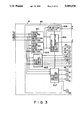
- FIG. 3 is a block diagram showing a multi-control section and its peripheral sections of the multi-system air conditioning machine according to the first embodiment
- FIG. 4 is a block diagram showing an outdoor control section and its peripheral sections of the multi-system air conditioning machine according to the first embodiment
- FIG. 5 is a diagram showing the flow of a refrigerant in a cooling operation mode of the multi-system air conditioning machine according to the first embodiment
- FIG. 6 is a flow chart for explaining an operation of the multi-system air conditioning machine according to the first embodiment
- FIG. 7 is a graph showing a change in opening degrees of PMVs of the multi-system air conditioning machine according to the first embodiment
- FIG. 8 is a graph for explaining outdoor fan control in the cooling operation mode of the multi-system air conditioning machine according to the first embodiment
- FIG. 9 is a diagram showing the flow of a refrigerant in a heating operation mode of the multi-system air conditioning machine according to the first embodiment
- FIG. 10 is a graph for explaining outdoor fan control in the heating operation mode of the multi-system air conditioning machine according to the first embodiment
- FIG. 11 is a diagram showing an entire arrangement of a multi-system air conditioning machine according to the second embodiment of the present invention.
- FIG. 12 is a block diagram showing a multi-control section and its peripheral sections of the multi-system air conditioning machine according to the second embodiment
- FIG. 13 is a block diagram showing an outdoor control section and its peripheral sections in the multi-system air conditioning machine according to the second embodiment
- FIG. 14 is a diagram showing an entire arrangement of a multi-system air conditioning machine according to the third embodiment of the present invention.
- FIG. 15 is a block diagram showing a multi-control section and its peripheral sections of the multi-system air conditioning machine according to the third embodiment.
- reference symbol A denotes an outdoor unit.
- a plurality of indoor units C 1 , C 2 , and C 3 are connected to the outdoor unit A through a switching unit B.
- the outdoor unit A includes a variable-capability compressor 1.
- the compressor 1 draws a refrigerant through a refrigerant intake port, compresses the refrigerant, and delivers the compressed refrigerant through a refrigerant outlet port.
- An outlet pipe 2 is connected to the refrigerant outlet port of the compressor 1.
- An intake pipe 3 is connected to the refrigerant intake port of the compressor 1.
- the outlet pipe 2 is branched into two outlet pipes 2a and 2b.
- the intake pipe 3 is branched into two intake pipes 3a and 3b.
- An outdoor heat exchanger 5 is connected to the outlet pipe 2b through a two-way valve 4.
- the outdoor heat exchanger 5 exchanges heat of the supplied refrigerant and heat of outer air.
- a liquid tank 10 is connected to the outdoor heat exchanger 5 through a series circuit consisting of a heating expansion valve 6 and a check valve 7, and a check valve 9.
- a liquid-side pipe W is connected to the liquid tank 10.
- the intake pipe 3a is connected to a refrigerant pipe between the two-way valve 4 and the outdoor heat exchanger 5 through a two-way valve 12.
- Cooling expansion valves 22, 32, and 42 are connected to the liquid-side pipes W through PMVs 20, 21, 31, and 41 in the switching unit B, respectively.
- Check valves 23, 33, and 43 are connected in parallel to the expansion valves 22, 32, and 42, respectively.
- Indoor heat exchangers 24, 34, and 44 of the indoor units C 1 , C 2 , and C 3 are connected to the expansion valves 22, 32, and 42, respectively. These indoor heat exchangers 24, 34, and 44 exchange heat of the supplied refrigerant and heat of inner air.
- Gas-side pipes G 1 , G 2 , and G 3 are connected to the indoor heat exchangers 24, 34, and 44, respectively.
- Each of the gas-side pipes G 1 , G 2 , and G 3 is branched into two pipes.
- One branch pipe of each of the gas-side pipes G 1 , G 2 , and G 3 is connected to the inlet pipe 3b through the corresponding one of two-way valves 25, 35, and 45 in the switching unit B.
- each of the gas-side pipes G 1 , G 2 , and G 3 is connected to the outlet pipe 2a through the corresponding one of two-way valves 26, 36, and 46 in the switching unit B.
- the outdoor unit A also includes an outdoor fan 13 for circulating the outer air in the outdoor heat exchanger 5.
- a temperature sensor 15 is attached to a pipe between the outdoor heat exchanger 5 and the valves 6 and 9. A temperature sensed by the temperature sensor 15 is denoted by reference symbol T 1 .
- a temperature sensor 16 is attached to the intake pipe 3. A temperature sensed by the temperature sensor 16 is denoted by reference symbol T 2 .
- a temperature sensor 17 is attached to the outdoor heat exchanger 5. A temperature sensed by the temperature sensor 17 is denoted by reference symbol T 3 .
- a heat-sensitive section 6a is attached to the refrigerant pipe between the two-way valves 4 and 12 and the outdoor heat exchanger 5.
- the heat-sensitive section 6a is a part attached to the heating expansion valve 6.
- the expansion valve 6 has a function of detecting a difference between a temperature sensed by the heat-sensitive section 6a and a temperature of a refrigerant supplied to the valve 6, i.e., a degree of superheat of the refrigerant in the outdoor heat exchanger 5.
- the expansion valve 6 also has a function of controlling an amount of refrigerant supplied to the outdoor heat exchanger 5 to set the detected degree of superheat to be constant.
- Heat-sensitive sections 22a, 32a, and 42a are respectively attached to corresponding ones (on the side of two-way valves 25, 35, and 45) of the branch pipes of the gas-side pipes G 1 , G 2 , and G 3 .
- the heat-sensitive sections 22a, 32a, and 42a are parts respectively attached to the cooling expansion valves 22, 32, and 42.
- the expansion valves 22, 32, and 42 respectively include the functions for detecting differences between temperatures sensed by the heat-sensitive sections 22a, 32a, and 42a and temperatures of the refrigerant in the valves 22, 32, and 42, i.e., a degree of superheat of the refrigerant supplied to the indoor heat exchangers 24, 34, and 44.
- the expansion valves 22, 32, and 42 respectively include the functions for regulating an amount of the refrigerant supplied to the indoor heat exchangers 24, 34, and 44 to set the detected degree of superheat to be constant.
- indoor units C 1 , C 2 , and C 3 include an indoor fans 28, 38, and 48 for circulating the inner air in the indoor heat exchangers 24, 34, and 44, respectively.
- the indoor unit A includes an outdoor control section 50.
- the outdoor control section 50 controls an inverter for driving a compressor, the two-way valve 4, the PMV 8, the two-way valve 12, and the outdoor fan 13.
- the switching unit B includes a multi-control section 60.
- the multi-control section 60 controls the PMVs 21, 31, and 41 and two-way valves 25, 35, 45, 26, 36, and 46.
- the indoor units C 1 , C 2 , C 3 include indoor control sections 70, respectively.
- Each indoor control section 70 transfers a request for a cooling operation mode and a cooling capability, or a request for a heating operation mode and a heating capability to the multi-control section 60, and controls the corresponding one of the indoor fans 28, 38, and 48.
- the outdoor control section 50, the multi-control section 60 and the two-way valves constitute the following means (1) to (4):
- the multi-control section 60 and the PMVs 20, 21, 31, and 41 constitute the following means (1) and (2):
- a setting means for setting an amount of refrigerant supplied to the outdoor heat exchanger to be relative to an amount of refrigerant supplied to one or the plurality of indoor units which request the heating operation mode in accordance with the total heating capability requested from one or the plurality of indoor units when the total cooling capability requested from one or the plurality of indoor units is larger than the total heating capability requested from the remaining one or the plurality of indoor units (cooling operation mode);
- a setting means for setting an amount of refrigerant supplied to the outdoor heat exchanger to be relative to an amount of refrigerant supplied to one or the plurality of indoor units which request the cooling operation mode in accordance with the total cooling capability requested from one or the plurality of indoor units when the total heating capability requested from one or the plurality of indoor units is larger than the total cooling capability requested from the remaining one or the plurality of indoor units (heating operation mode).
- the outdoor control section 50 and the temperature sensors 15 and 17 constitute a detecting means for detecting a degree ⁇ of supercool of the refrigerant in the outdoor heat exchanger 5.
- the degree ⁇ of supercool is detected as a difference (T 3 -T 1 ) between the temperature T 3 of the refrigerant supplied to the outdoor heat exchanger 5 and the temperature T 1 of the refrigerant supplied from the outdoor heat exchanger 5.
- the outdoor control section 50 and the temperature sensors 15 and 16 constitute a detecting means for detecting a degree ⁇ of superheat of the refrigerant in the outdoor heat exchanger 5.
- the degree ⁇ of superheat is detected as a difference (T 2 -T 1 ) between the temperature T 2 of the refrigerant supplied from the outdoor heat exchanger 5 and the temperature T 1 of the refrigerant supplied to the outdoor heat exchanger 5.
- the outdoor control section 50 serves as a control means for controlling a speed of the outdoor fan 13 so that the degree ⁇ of supercool and the degree ⁇ of superheat which are detected respectively fall within predetermined ranges.
- each indoor control section 70 and its peripheral sections is shown in FIG. 2.
- Each indoor control section 70 includes a fan drive control circuit 71, a load detecting section 72, and a signal processing circuit 73.
- the fan drive control circuit 71 in the indoor unit C 1 controls a motor 28M for the indoor fan 28 in accordance with an operation of an operation section 81.
- the fan drive control circuit 71 in the indoor unit C 2 controls a motor 38M for the indoor fan 38 in accordance with an operation of the operation section 81.
- the fan drive control circuit 71 in the indoor unit C 3 controls a motor 48M for the indoor fan 48 in accordance with an operation of the operation section 81.
- the load detecting section 72 in the indoor unit C 1 has the following functions (1) to (3):
- the load detecting section 72 in the indoor unit C 2 has the following functions (1) to (3):
- the load detecting section 72 in the indoor unit C 3 has the following functions (1) to (3):
- FIG. 3 A detailed arrangement of the multi-control section 60 and its peripheral circuits is shown in FIG. 3.
- the multi-control section 60 includes a total cooling load detecting section 601, a total heating load detecting section 602, a valve drive control circuit 603, an operation mode determination section 604, a selection circuit 605, and a valve drive control circuit 607.
- the total cooling load detecting section 60 has the following functions (1) and (2):
- the total heating load detecting section 602 has the following functions (1) and (2):
- the valve drive control circuit 603 has the following functions (1) and (2):
- the operation mode determination section 604 has the following functions (1) to (3):
- the selection circuit 605 has the following functions (1) and (2):
- the valve drive control circuit 607 controls the PMVs 20, 21, 31, and 41.
- the circuit 607 has the following functions.
- valve drive control circuit 607 executes the following functions (1) to (3) when a cooling operation mode is determined by the operation mode determination section 604:
- a function of setting the opening degree of the PMV 20 to be relative to that of the PMV 21 corresponding to the indoor unit C 1 in accordance with a heating capability requested by the signal H 1 when the signal H 1 represents a request for a heating operation mode i.e., the opening degree of the PMV 21 is increased and that of the PMV 20 is decreased when the requested heating capability is large, and the opening degree of the PMV 21 is decreased and that of the PMV 20 is increased when the requested heating capability is small
- a function of setting the opening degree of the PMV 20 to be relative to that of the PMV 31 corresponding to the indoor unit C 2 in accordance with a heating capability requested by the signal H 2 when the signal H 2 represents a request for a heating operation mode i.e., the opening degree of the PMV 31 is increased and that of the PMV 20 is decreased when the requested heating capability is large, and the opening degree of the PMV 31 is decreased and that of the PMV 20 is increased when the requested heating capability is small
- the valve drive control circuit 607 executes the following functions (4) to (6) when a heating operation mode is determined by the operation mode determination section 604:
- (6) a function of setting the opening degree of the PMV 20 to be relative to that of the PMV 21 corresponding to the indoor unit C 1 in accordance with cooling capability requested by the signal H 1 when the signal H 1 represents a request for a cooling operation mode (i.e., the opening degree of the PMV 21 is increased and that of the PMV 20 is decreased when the requested cooling capability is large, and the opening degree of the PMV 21 is decreased and that of the PMV 20 is increased when the requested cooling capability is small), a function of setting the opening degree of the PMV 20 to be relative to that of the PMV 31 corresponding to the indoor unit C 2 in accordance with a cooling capability requested by the signal H 2 when the signal H 2 represents a request for a cooling operation mode (i.e., the opening degree of the PMV 31 is increased and that of the PMV 20 is decreased when the requested cooling capability is large, and the opening degree of the PMV 31 is decreased and that of the PMV 20 is increased when the requested cooling capability is small, and a function of setting the opening degree of the PM
- FIG. 4 A detailed arrangement of the outdoor control section 50 and its peripheral circuits is shown in FIG. 4.
- Reference numeral 501 denotes a commercial AC power source.
- An inverter 502 and a voltage controller 503 are connected to the power source 501.
- the inverter 502 rectifies a voltage of the power source 501.
- the rectified voltage is converted into an AC voltage having a predetermined frequency, and is output.
- An output voltage from the inverter 502 is supplied to a motor 1M for the compressor 1 as drive power.
- the voltage controller 503 converts a voltage of the power source 501 into a voltage having a predetermined level to output the converted voltage.
- An output voltage from the voltage controller 503 is supplied to a motor 13M for the outdoor fan 13 as drive power.
- the outdoor control section 50 includes an inverter drive circuit 511, a selection circuit 512, a valve drive control circuit 513, a degree-of-superheat detecting section 514, a degree-of-supercool detecting section 515, speed control sections 516 and 517, and preset value circuits 518 and 519.
- the inverter drive circuit 511 has the following functions (1) and (2):
- the selection circuit 512 has the following functions (1) and (2):
- the valve drive control circuit 513 has the following functions (1) and (2):
- the degree-of-supercool detecting section 514 detects a difference (T 3 -T 1 ) between the temperature T 3 sensed by the temperature sensor 17 and the temperature T 1 sensed by the temperature sensor 15 as a degree ⁇ of supercool.
- the degree-of-superheat detecting section 515 detects a difference (T 2 -T 1 ) between the temperature T 2 sensed by the temperature sensor 16 add the temperature T 1 sensed by the temperature sensor 15 as a degree ⁇ of superheat.
- the speed control section 516 has the following functions (1) to (3):
- the speed control section 517 has the following functions (1) to (3):
- the indoor units C 1 and C 2 request a cooling operation mode
- the indoor unit C 3 requests a heating operation mode.
- a requested total cooling capability is larger than a requested total heating capability.
- a cooling operation mode is determined, the two-way valve 4 in the outdoor unit A is opened (represented by white), and the two-way valve 12 is closed (represented by black), as shown in FIG. 5.
- the outdoor heat exchanger 5 is connected to the outlet pipe 2b of the compressor 1.
- the two-way valves 25, 35, and 46 are opened (represented by white), and the two-way valves 26, 36, and 45 are closed (represented by black).
- the gas-side pipes G 1 and G 2 the indoor units C 1 and C 2 which request a cooling operation mode are connected to the intake pipe 3b of the compressor 1.
- the gas-side pipe G 3 of the indoor unit C 3 which requests a heating operation mode is connected to the outlet pipe 2a of the compressor 1.
- the refrigerant delivered from the compressor 1 is, therefore, supplied to the outdoor heat exchanger 5 through the two-way valve 4.
- the refrigerant In the outdoor heat exchanger 5, the refrigerant is condensed.
- the refrigerant which flows through the outdoor heat exchanger 5 is supplied to the indoor units C 1 and C 2 through the check valve 9, the liquid tank 10, the PMVs 20, 21, and 31, and the expansion valves 22 and 32.
- the indoor units C 1 and C 2 the refrigerant evaporates.
- the refrigerant supplied from the indoor units C 1 and C 2 is drawn into the compressor 1 through the two-way valves 25 and 35.
- a part of the refrigerant delivered from the compressor 1 is supplied to the indoor unit C 3 through the two-way valve 46.
- the indoor unit C 3 the refrigerant is condensed.
- the refrigerant supplied from the indoor unit C 3 merges into the flow of the refrigerant supplied to the PMVs 21 and 31, and the indoor units C 1 and C 2 through the check valve 43 and the PMV 41.
- the outdoor heat exchanger 5 serves as a condenser
- the indoor heat exchangers 24 and 34 serve as evaporators
- the indoor heat exchanger 44 serves as a condenser.
- the heat absorbed by the indoor units C 1 and C 2 is partially utilized to dissipate the heat from the indoor unit C 3 .
- An output frequency of the inverter 502 is set in accordance with a requested total cooling capability. Therefore, the compressor 1 exhibits a capability for sufficiently covering a cooling capability of the indoor units C 1 and C 2 each having a large load.
- the opening degree of each of the PMVs 21 and 31 is, at this time, controlled in accordance with the cooling capability requested from the indoor units C 1 and C 2 , and the refrigerant is properly distributed to the indoor units C 1 and C 2 .
- Amounts of refrigerant supplied to the indoor heat exchangers 24 and 34 are controlled by the expansion valves 22 and 32, respectively, and a degree of superheat of the refrigerant is kept constant.
- a sufficient heating capability of the indoor unit C 3 can be assured under the control shown in FIGS. 6, 7, and 8.
- step S1 It is discriminated whether a cooling or heating operation mode is set.
- the opening degree of the PMV 41 corresponding to the indoor unit C 3 on the heating side is set in proportion to a heating capability requested by the indoor unit C 3 (step S2).
- the opening degree of the PMV 20 is set in inverse proportion to a heating capability requested by the indoor unit C 3 (step S3).
- the opening degree of the PMV 41 is increased, and that of the PMV 20 is decreased. If a small heating capability is requested, the opening degree of the PMV 41 is decreased, and that of the PMV 20 is increased.
- the PMV 20 is fully closed.
- the requested heating capability is set to be "0”
- the PMV 41 is fully closed, and the PMV 20 is fully opened.
- a proper amount of refrigerant is, therefore, distributed to the indoor unit C 3 and the outdoor heat exchanger 5, thus assuring a sufficient heating capability for the indoor unit C 3 .
- a degree ⁇ of supercool of the refrigerant in the outdoor heat exchanger 5 is detected (step S4).
- step S5 If the detected degree ⁇ of supercool is below 10° C. (step S5), the outdoor fan 13 is driven at a maximum speed (step S11).
- step S5 If the degree ⁇ of supercool is, however, equal to or higher than 10° C. (step S5), a speed of the outdoor fan 13 is reduced (step S6).
- the degree ⁇ of supercool falls within 10° C., thus continuing a stable operation of the refrigerant apparatus.
- the indoor units C 1 and C 2 request a heating operation mode
- the indoor unit C 3 requests a cooling operation mode.
- a requested total heating capability is larger than a requested total cooling capability.
- a heating operation mode is determined, the two-way valve 4 in the outdoor unit A is closed (represented by black), and the two-way valve 12 is opened (represented by white), as shown in FIG. 9.
- the outdoor heat exchanger 5 is connected to the intake pipe 3a of the compressor 1.
- the two-way valves 45, 26, and 36 are opened (represented by white), and the two-way valves 25, 35, and 46 are closed (represented by black).
- the gas-side pipes G 1 and G 2 in the indoor units C 1 and C 2 which request a heating operation mode are connected to the outlet pipe 2a of the compressor 1.
- the gas-side pipe G 3 of the indoor unit C 3 which requests a cooling operation mode is connected to the intake pipe 3b of the compressor 1.
- the refrigerant components delivered from the compressor 1 are, therefore, supplied to the indoor units C 1 and C 2 through the two-way valve 26 and 36, respectively.
- the indoor units C 1 and C 2 the refrigerant is condensed.
- the refrigerant which flows through the indoor units C 1 and C 2 is supplied to the outdoor heat exchanger 5 through the check valves 23 and 33, the PMVs 21 and 31, the liquid tank 10, the check valve 7, and the expansion valve 6.
- the refrigerant evaporates.
- the refrigerant supplied from the outdoor heat exchanger 5 is drawn into the compressor 1 through the two-way valve 12.
- the refrigerant which flows through the indoor units C 1 and C 2 , the check valve 23 and 33, and the PMVs 21 and 31 is partially supplied to the indoor unit C 3 through the PMV 41 and the expansion valve 42.
- the refrigerant evaporates.
- the refrigerant supplied from the indoor unit C 3 is drawn into the compressor 1 through two-way valve 45.
- the indoor heat exchangers 24 and 34 serve as condensers
- the outdoor heat exchanger 5 serves as an evaporator
- the indoor heat exchanger 44 serves as an evaporator.
- the heat absorbed by the outdoor and indoor heat exchangers 5 and 44 is utilized to dissipate the heat from the indoor units C 1 and C 2 .
- An output frequency of the inverter 502 is set in accordance with a requested total heating capability. Therefore, the compressor 1 exhibits a capability for sufficiently covering a heating capability of the indoor units C 1 and C 2 each having a large load.
- the opening degree of each of the PMVs 21 and 31 is controlled in accordance with the heating capability requested from the indoor units C 1 and C 2 , and the refrigerant is properly distributed to the indoor units C 1 and C 2 .
- a sufficient cooling capability of the indoor unit C 3 can be assured under the control shown in FIGS. 6, 7, and 10.
- step S1 It is discriminated whether a cooling or heating operation mode is set.
- the opening degree of the PMV 41 corresponding to the indoor unit C 3 on the cooling side is set in proportion to a cooling capability requested by the indoor unit C 3 (step S7).
- the opening degree of the PMV 20 is set in inverse proportion to a cooling capability requested by the indoor unit C 3 (step S8).
- the opening degree of the PMV 41 is increased, and that of the PMV 20 is decreased. If a small cooling capability is requested, the opening degree of the PMV 41 is decreased, and that of the PMV 20 is increased.
- a proper amount of refrigerant is, therefore, distributed to the indoor unit C 3 and the outdoor heat exchanger 5, thus assuring a sufficient cooling capability for the indoor unit C 3 .
- the opening degree of the expansion valve 6 is changed to set the degree ⁇ of superheat of the refrigerant in the outdoor heat exchanger 5 to be constant.
- the expansion valve 6 may be fully opened while the degree ⁇ of superheat is not decreased. In this case, the degree ⁇ of superheat cannot be kept constant.
- step S9 the degree ⁇ of superheat of the refrigerant in the outdoor heat exchanger 5 is detected.
- step S10 If the detected degree ⁇ of superheat is below 8° C. (step S10), the outdoor fan 13 is driven at a maximum speed (step S11).
- step S10 If the degree ⁇ of superheat is, however, equal to or higher than 8° C. (step S10), a speed of the outdoor fan 13 is reduced (step S6).
- the degree ⁇ of superheat falls within 8° C., thus continuing a stable operation of the refrigerant apparatus.
- FIGS. 11, 12, and 13 The second embodiment of the present invention will be described below with reference to FIGS. 11, 12, and 13.
- the same reference numerals in FIGS. 11, 12, and 13 denote the same parts as in the first embodiment, and a description thereof will be omitted.
- a PMV 20 is disposed at a pipe between two-way valves 4 and 12 and an outdoor heat exchanger 5.
- a valve drive control circuit 607 in a switching unit B does not drive the PMV 20, but outputs an opening degree setting signal L with respect to the PMV 20.
- the opening degree setting signal L is supplied to an outdoor control section 50.
- a valve drive control circuit 520 is additionally arranged in the outdoor control section 50.
- the valve drive control circuit 20 receives the opening degree setting signal L.
- the valve drive control circuit 520 controls the opening degree of the PMV 20 in response to the opening degree setting signal L.
- indoor units C 1 and C 2 request a cooling operation mode
- an indoor unit C 3 requests a heating operation mode.
- a requested total cooling capability is larger than a requested total heating capability.
- a cooling operation mode is determined, the two-way valve 4 in an outdoor unit A is opened (represented by white), and the two-way valve 12 is closed (represented by black), as shown in FIG. 11.
- the outdoor heat exchanger 5 is connected to an outlet pipe 2b of a compressor 1.
- two-way valves 25, 35, and 46 are opened (represented by white), and two-way valves 26, 36, and 45 are closed (represented by black).
- gas-side pipes G 1 and G 2 in the indoor units C 1 and C 2 which request a cooling operation mode are connected to an intake pipe 3b of the compressor 1.
- a gas-side pipe G 3 of the indoor unit C 3 which requests a heating operation mode is connected to an outlet pipe 2a of the compressor 1.
- the refrigerant delivered from the compressor 1 is, therefore, supplied to the outdoor heat exchanger 5 through the two-way valve 4 and the PMV 20.
- the refrigerant In the outdoor heat exchanger 5, the refrigerant is condensed.
- the refrigerant which flows through the outdoor heat exchanger 5 is supplied to the indoor units C 1 and C 2 through a check valve 9, a liquid tank 10, PMVs 21 and 31, and expansion valves 22 and 32.
- the indoor units C 1 and C 2 the refrigerant evaporates.
- the refrigerant supplied from the indoor units C 1 and C 2 is drawn into the compressor 1 through the two-way valves 25 and 35.
- a part of the refrigerant delivered from the compressor 1 is supplied to the indoor unit C 3 through the two-way valve 46.
- the indoor unit C 3 the refrigerant is condensed.
- the refrigerant supplied from the indoor unit C 3 merges into the flow of the refrigerant supplied to the PMVs 21 and 31, and the indoor units C 1 and C 2 through a check valve 43 and a PMV 41.
- the outdoor heat exchanger 5 serves as a condenser
- indoor heat exchangers 24 and 34 serve as evaporators
- an indoor heat exchanger 44 serves as a condenser
- the heat absorbed by the indoor units C 1 and C 2 is partially utilized to dissipate the heat from the indoor unit C 3 .
- An output frequency of an inverter 502 is set in accordance with a requested total cooling capability. Therefore, the compressor 1 exhibits a capability for sufficiently covering a cooling capability of the indoor units C 1 and C 2 each having a large load.
- the opening degree of each of the PMVs 21 and 31 is, at this time, controlled in accordance with the cooling capability requested from the indoor units C 1 and C 2 , and the refrigerant is properly distributed to the indoor units C 1 and C 2 .
- Amounts of refrigerant supplied to the indoor heat exchangers 24 and 34 are controlled by the expansion valves 22 and 32, respectively, and a degree of superheat of the refrigerant i kept constant.
- a sufficient heating capability of the indoor unit C 3 can be assured under the control shown in FIGS. 6, 7, and 8.
- step S1 It is discriminated whether a cooling or heating operation mode is set.
- the opening degree of the PMV 41 corresponding to the indoor unit C 3 on the heating side is set in proportion to a heating capability requested by the indoor unit C 3 (step S2).
- the opening degree of the PMV 20 is set in inverse proportion to a heating capability requested by the indoor unit C 3 (step S3).
- the opening degree of the PMV 41 is increased, and that of the PMV 20 is decreased. If a small heating capability is requested, the opening degree of the PMV 41 is decreased, and that of the PMV 20 is increased.
- the PMV 41 is fully opened, the PMV 20 is fully closed.
- the requested heating capability is set to be "0"
- the PMV 41 is fully closed, and the PMV 20 is fully opened.
- a proper amount of refrigerant is, therefore, distributed to the indoor unit C 3 and the outdoor heat exchanger 5, thus assuring a sufficient heating capability for the indoor unit C 3 .
- a degree ⁇ of supercool of the refrigerant in the outdoor heat exchanger 5 is detected (step S4).
- step S5 If the detected degree ⁇ of supercool is below 10° C. (step S5), an outdoor fan 13 is driven at a maximum speed (step S11).
- step S5 If the degree ⁇ of supercool is, however, equal to or exceeds 10° C. (step S5), a speed of the outdoor fan 13 is reduced (step S6).
- the degree ⁇ of supercool falls within 10° C., thus continuing a stable operation of the refrigerant apparatus.
- the PMV 41 is fully opened, and the PMV 20 is fully closed, a refrigerant does not flow into the outdoor heat exchanger 5.
- An operation in a heating operation mode is the same as in the first embodiment.
- FIGS. 14 and 15 denote the same parts as in the second embodiment, and a description thereof will be omitted.
- the two-way valve 4 in the outdoor unit A is replaced by a PMV 20.
- a valve drive control circuit 513 in the indoor unit A controls only an opening/closing state of a two-way valve 12 on the basis of a signal J from a multi-control section 60.
- a valve drive control circuit 520 receives the signal J from the multi-control section 60.
- the valve drive control circuit 520 controls the opening degree of the PMV 20 on the basis of a signal L from a switching unit B in a cooling operation mode, and fully closes the PMV 20 in a heating operation mode.
- the same operation as in the second embodiment can be obtained in only a cooling operation mode.
- the opening degree of the PMV 20 is not controlled in a heating operation mode, a refrigerant is not distributed.
Landscapes
- Engineering & Computer Science (AREA)
- Mechanical Engineering (AREA)
- General Engineering & Computer Science (AREA)
- Physics & Mathematics (AREA)
- Thermal Sciences (AREA)
- Chemical & Material Sciences (AREA)
- Combustion & Propulsion (AREA)
- Life Sciences & Earth Sciences (AREA)
- Sustainable Development (AREA)
- Air Conditioning Control Device (AREA)
Applications Claiming Priority (2)
| Application Number | Priority Date | Filing Date | Title |
|---|---|---|---|
| JP1045738A JPH02223755A (ja) | 1989-02-27 | 1989-02-27 | 空気調和機 |
| JP1-45738 | 1989-02-27 |
Publications (1)
| Publication Number | Publication Date |
|---|---|
| US5009078A true US5009078A (en) | 1991-04-23 |
Family
ID=12727658
Family Applications (1)
| Application Number | Title | Priority Date | Filing Date |
|---|---|---|---|
| US07/483,654 Expired - Fee Related US5009078A (en) | 1989-02-27 | 1990-02-23 | Multi-system air conditioning machine |
Country Status (5)
| Country | Link |
|---|---|
| US (1) | US5009078A (ko) |
| JP (1) | JPH02223755A (ko) |
| KR (1) | KR920007811B1 (ko) |
| AU (1) | AU600419B1 (ko) |
| GB (1) | GB2229551B (ko) |
Cited By (10)
| Publication number | Priority date | Publication date | Assignee | Title |
|---|---|---|---|---|
| EP0586193A1 (en) * | 1992-08-31 | 1994-03-09 | Hitachi, Ltd. | Refrigeration cycle |
| EP0692683A3 (en) * | 1994-07-14 | 1997-11-05 | Kabushiki Kaisha Toshiba | Air conditioning apparatus having an outdoor unit to which a plurality of indoor units are connected |
| US5782101A (en) * | 1997-02-27 | 1998-07-21 | Carrier Corporation | Heat pump operating in the heating mode refrigerant pressure control |
| US6212892B1 (en) * | 1998-07-27 | 2001-04-10 | Alexander Pinkus Rafalovich | Air conditioner and heat pump with dehumidification |
| EP1347253A1 (de) * | 2002-03-23 | 2003-09-24 | Colt International Holdings Ag | Vorrichtung und Verfahren zur Klimatisierung insbesondere Kühlen und Heizen in Gebäuden |
| EP1437558A1 (en) | 2003-01-13 | 2004-07-14 | Lg Electronics Inc. | Method for operating multi-type air conditioner |
| EP1526341A1 (en) * | 2003-10-21 | 2005-04-27 | Samsung Electronics Co., Ltd. | Multi-unit air conditioner and method for controlling the same |
| US20110036116A1 (en) * | 2009-08-11 | 2011-02-17 | Te-Shou Lee | Structural improvement for electric energy saving equipment |
| US20160238285A1 (en) * | 2013-10-07 | 2016-08-18 | Daikin Industries, Ltd. | Heat-recoverty-type refrigerating apparatus |
| US9726409B2 (en) * | 2011-06-14 | 2017-08-08 | Mitsubishi Electric Corporation | Air-conditioning apparatus |
Families Citing this family (6)
| Publication number | Priority date | Publication date | Assignee | Title |
|---|---|---|---|---|
| JPH037853A (ja) * | 1989-06-05 | 1991-01-16 | Toshiba Corp | 空気調和機 |
| JPH0336474A (ja) * | 1989-07-03 | 1991-02-18 | Toshiba Corp | 空気調和機 |
| JPH0359362A (ja) * | 1989-07-28 | 1991-03-14 | Toshiba Corp | 空気調和機 |
| JP2909190B2 (ja) * | 1990-11-02 | 1999-06-23 | 株式会社東芝 | 空気調和機 |
| JPH09236332A (ja) * | 1996-02-29 | 1997-09-09 | Sanyo Electric Co Ltd | 空調用ヒートポンプ装置 |
| CN112032912A (zh) * | 2020-08-17 | 2020-12-04 | 青岛海尔空调电子有限公司 | 多联式空调系统的控制方法 |
Citations (3)
| Publication number | Priority date | Publication date | Assignee | Title |
|---|---|---|---|---|
| JPS6145145A (ja) * | 1984-08-07 | 1986-03-05 | Aisin Warner Ltd | 自動変速機 |
| US4862705A (en) * | 1987-11-18 | 1989-09-05 | Mitsubishi Denki Kabushiki Kaisha | Air conditioner |
| US4878357A (en) * | 1987-12-21 | 1989-11-07 | Sanyo Electric Co., Ltd. | Air-conditioning apparatus |
-
1989
- 1989-02-27 JP JP1045738A patent/JPH02223755A/ja active Pending
-
1990
- 1990-01-31 KR KR1019900001252A patent/KR920007811B1/ko not_active IP Right Cessation
- 1990-02-19 GB GB9003711A patent/GB2229551B/en not_active Expired - Fee Related
- 1990-02-20 AU AU49922/90A patent/AU600419B1/en not_active Ceased
- 1990-02-23 US US07/483,654 patent/US5009078A/en not_active Expired - Fee Related
Patent Citations (3)
| Publication number | Priority date | Publication date | Assignee | Title |
|---|---|---|---|---|
| JPS6145145A (ja) * | 1984-08-07 | 1986-03-05 | Aisin Warner Ltd | 自動変速機 |
| US4862705A (en) * | 1987-11-18 | 1989-09-05 | Mitsubishi Denki Kabushiki Kaisha | Air conditioner |
| US4878357A (en) * | 1987-12-21 | 1989-11-07 | Sanyo Electric Co., Ltd. | Air-conditioning apparatus |
Cited By (18)
| Publication number | Priority date | Publication date | Assignee | Title |
|---|---|---|---|---|
| EP0586193A1 (en) * | 1992-08-31 | 1994-03-09 | Hitachi, Ltd. | Refrigeration cycle |
| US5353604A (en) * | 1992-08-31 | 1994-10-11 | Hitachi, Ltd. | Refrigeration cycle |
| EP0692683A3 (en) * | 1994-07-14 | 1997-11-05 | Kabushiki Kaisha Toshiba | Air conditioning apparatus having an outdoor unit to which a plurality of indoor units are connected |
| US5782101A (en) * | 1997-02-27 | 1998-07-21 | Carrier Corporation | Heat pump operating in the heating mode refrigerant pressure control |
| EP0862031A3 (en) * | 1997-02-27 | 2002-01-02 | Carrier Corporation | Heat pump operating in the heating mode refrigerant pressure control |
| US6212892B1 (en) * | 1998-07-27 | 2001-04-10 | Alexander Pinkus Rafalovich | Air conditioner and heat pump with dehumidification |
| WO2002059532A1 (en) * | 1998-07-27 | 2002-08-01 | Alexander Rafalovich | Air conditioner and heat pump with dehumidification |
| EP1347253A1 (de) * | 2002-03-23 | 2003-09-24 | Colt International Holdings Ag | Vorrichtung und Verfahren zur Klimatisierung insbesondere Kühlen und Heizen in Gebäuden |
| EP1437558A1 (en) | 2003-01-13 | 2004-07-14 | Lg Electronics Inc. | Method for operating multi-type air conditioner |
| US20040138784A1 (en) * | 2003-01-13 | 2004-07-15 | Lg Electronics Inc. | Method for operating multi-type air conditioner |
| US6922613B2 (en) | 2003-01-13 | 2005-07-26 | Lg Electronics Inc. | Method for operating multi-type air conditioner |
| EP1526341A1 (en) * | 2003-10-21 | 2005-04-27 | Samsung Electronics Co., Ltd. | Multi-unit air conditioner and method for controlling the same |
| CN1324272C (zh) * | 2003-10-21 | 2007-07-04 | 三星电子株式会社 | 空调及其控制方法 |
| US20110036116A1 (en) * | 2009-08-11 | 2011-02-17 | Te-Shou Lee | Structural improvement for electric energy saving equipment |
| US8186175B2 (en) * | 2009-08-11 | 2012-05-29 | Te-Shou Lee | Structural improvement for electric energy saving equipment |
| US9726409B2 (en) * | 2011-06-14 | 2017-08-08 | Mitsubishi Electric Corporation | Air-conditioning apparatus |
| US20160238285A1 (en) * | 2013-10-07 | 2016-08-18 | Daikin Industries, Ltd. | Heat-recoverty-type refrigerating apparatus |
| US9784481B2 (en) * | 2013-10-07 | 2017-10-10 | Daikin Industries, Ltd. | Heat-recovery-type refrigerating apparatus |
Also Published As
| Publication number | Publication date |
|---|---|
| GB2229551B (en) | 1993-10-06 |
| KR900013259A (ko) | 1990-09-05 |
| JPH02223755A (ja) | 1990-09-06 |
| GB2229551A (en) | 1990-09-26 |
| AU600419B1 (en) | 1990-08-09 |
| KR920007811B1 (ko) | 1992-09-17 |
| GB9003711D0 (en) | 1990-04-18 |
Similar Documents
| Publication | Publication Date | Title |
|---|---|---|
| US5050396A (en) | Multi-system air conditioning machine | |
| US5009078A (en) | Multi-system air conditioning machine | |
| US5344069A (en) | Air conditioning apparatus for distributing primarily-conditioned air to rooms | |
| US5046323A (en) | Multi-system air conditioner | |
| US5231845A (en) | Air conditioning apparatus with dehumidifying operation function | |
| US7155922B2 (en) | Energy efficient heat pump systems for water heating and air conditioning | |
| US5009077A (en) | Multi-system air conditioner | |
| US5004149A (en) | Central air conditioning system having compensating control function for total heat load in a plurality of rooms | |
| US4916913A (en) | Air conditioning apparatus having two refrigerating circuits in central unit and control method of defrosting the same | |
| JP2823297B2 (ja) | 空気調和機 | |
| KR930007964B1 (ko) | 공기조화기 | |
| US4368621A (en) | Method of operating air conditioner | |
| JP2974381B2 (ja) | 空気調和機 | |
| JP2777176B2 (ja) | 空気調和機 | |
| JP2716559B2 (ja) | 冷暖混在型多室空気調和装置 | |
| JP2536313B2 (ja) | 空気調和装置の運転制御装置 | |
| JP3035599B2 (ja) | 空気調和機 | |
| JP2848691B2 (ja) | 空気調和機 | |
| JPH0526532A (ja) | 空気調和機 | |
| US20230324070A1 (en) | Systems and methods to operate hvac system in variable operating mode | |
| JPH0682119A (ja) | 空気調和機 | |
| JP2937304B2 (ja) | ダクト式空調システム | |
| JPS60133274A (ja) | 多室形冷暖房装置 | |
| JPH07332739A (ja) | 空気調和機 | |
| JPH01121650A (ja) | 空気調和機のインジェクション制御装置 |
Legal Events
| Date | Code | Title | Description |
|---|---|---|---|
| AS | Assignment |
Owner name: KABUSHIKI KAISHA TOSHIBA, A CORP. OF JAPAN, JAPAN Free format text: ASSIGNMENT OF ASSIGNORS INTEREST.;ASSIGNORS:OHKOSHI, SEIZI;KUWAHARA, EIJI;REEL/FRAME:005225/0169 Effective date: 19900213 |
|
| FEPP | Fee payment procedure |
Free format text: PAYOR NUMBER ASSIGNED (ORIGINAL EVENT CODE: ASPN); ENTITY STATUS OF PATENT OWNER: LARGE ENTITY |
|
| FPAY | Fee payment |
Year of fee payment: 4 |
|
| REMI | Maintenance fee reminder mailed | ||
| LAPS | Lapse for failure to pay maintenance fees | ||
| FP | Lapsed due to failure to pay maintenance fee |
Effective date: 19990423 |
|
| STCH | Information on status: patent discontinuation |
Free format text: PATENT EXPIRED DUE TO NONPAYMENT OF MAINTENANCE FEES UNDER 37 CFR 1.362 |