US4969142A - Reproduction of optically recorded signal - Google Patents
Reproduction of optically recorded signal Download PDFInfo
- Publication number
- US4969142A US4969142A US07/352,651 US35265189A US4969142A US 4969142 A US4969142 A US 4969142A US 35265189 A US35265189 A US 35265189A US 4969142 A US4969142 A US 4969142A
- Authority
- US
- United States
- Prior art keywords
- light
- objective lens
- signal
- optical disk
- recorded
- Prior art date
- Legal status (The legal status is an assumption and is not a legal conclusion. Google has not performed a legal analysis and makes no representation as to the accuracy of the status listed.)
- Expired - Lifetime
Links
Images


Classifications
-
- G—PHYSICS
- G11—INFORMATION STORAGE
- G11B—INFORMATION STORAGE BASED ON RELATIVE MOVEMENT BETWEEN RECORD CARRIER AND TRANSDUCER
- G11B7/00—Recording or reproducing by optical means, e.g. recording using a thermal beam of optical radiation by modifying optical properties or the physical structure, reproducing using an optical beam at lower power by sensing optical properties; Record carriers therefor
- G11B7/004—Recording, reproducing or erasing methods; Read, write or erase circuits therefor
- G11B7/005—Reproducing
-
- G—PHYSICS
- G11—INFORMATION STORAGE
- G11B—INFORMATION STORAGE BASED ON RELATIVE MOVEMENT BETWEEN RECORD CARRIER AND TRANSDUCER
- G11B7/00—Recording or reproducing by optical means, e.g. recording using a thermal beam of optical radiation by modifying optical properties or the physical structure, reproducing using an optical beam at lower power by sensing optical properties; Record carriers therefor
- G11B7/12—Heads, e.g. forming of the optical beam spot or modulation of the optical beam
- G11B7/135—Means for guiding the beam from the source to the record carrier or from the record carrier to the detector
Definitions
- the present invention relates generally to reproduction of an optically recorded signal, and particularly concerned with the reproduction of an optically recorded signal of high frequency.
- FIG. 1 schematically shows the surface of an optical disk having U-shaped grooves 1 whereon signals are recorded.
- the pitch between the parallel neighboring grooves in order to sufficiently minimize cross-talk from the neighboring grooves, the pitch between the parallel neighboring grooves (track pitch) has to be more than twice the wavelength of the laser light.
- FIG. 2 schematically shows surface of an optical disk having V-shaped grooves 2 on which signals are to be recorded.
- the optical recording disk of FIG. 2 having the V-shaped grooves cross-talk from the neighboring grooves can be minimized even when the pitch between the bottoms of the V-shaped grooves are selected to be just twice the wavelength of the laser light. That is, the V-shaped groove type optical disk is capable of storing higher recording density by decreasing track pitches in comparison with those of U-shaped groove type recording disk (M. Nagashima; Applied Physics Letters, Vol. 42, P. 144, 1983 or U.S. Ser. No. 331,840 or EPC Application No. 81,110,606.1).
- a semiconductor laser which is capable of direct modulation and is small in size, is widely utilized.
- a high power semiconductor laser which can be used for recording the information and has a practically usable life time, for instance as shown in FIG. 3, has an elliptic light emitting facet 3 and sections of the emitted light beam 4 are also of elliptic shape.
- the wavelength of oscillated light is about 0.8 ⁇ m and the power of emitted light is around 25 mW.
- FIG. 4 shows an optical system of the general configuration of an apparatus for recording and reproducing information signal on a disk.
- a light beam emitter part 57 has a semiconductor laser 5 to emit a coherent light, a collimate lens 6 for making the light from the semiconductor laser 5 a parallel light beam and a beam expander 7 which expands and reforms the collimated beam of the elliptic section to a beam of parallel light of substantially circular section.
- the laser beam X from the light beam emitter part 57 is then led to a polarized beam splitter 8, a quarter wave plate 9, and focussed by an objective lens 10 onto a recorded surface 11 of an optical disk.
- Light reflected from the recorded surface 11 is guided again through the objective lens 10, the quarter wave plate 9 and the polarized beam splitter 8, and then led through a convex lens 12, from which one part of the reflected light is further reflected by a mirror 13 to irradiate a photo-detector K for focussing control.
- the other part of the light from the convex lens 12 is led to another photo-detector M, and the signals detected by the photo-detectors M are used for reproducing the information and controlling tracking.
- Shapes of the beam of the reflected light and the light receiving face of the photo-detector M for the system of U-shaped groove optical disk and for the system of V-shaped groove optical disk are shown in FIG. 5 and FIG. 6, respectively. Tracking of the light beam along the U-shaped grooves is made by adjusting the light intensity of the beam 16 received by light detection parts 14 and 15 to become equal each other, and by utilizing signals based on sum of the light intensity on the light detector parts 14 and 15, the signal is reproduced.
- the tracking control is made by slightly wobbling the V-shaped grooves to produce wobble containing output from the light detection parts 17 and 18 followed by extracting signals of the wobbling frequency therefrom (U.S. Ser. No. 525,412 and EPC Application No. 83,304,832.5).
- an objective lens of numerical aperture (NA) of 0.5 is used
- an objective lens of numerical aperture (NA) of 0.6 is used in a manner that the laser beam is incident only to a central part of the lens corresponding to NA 0.5.
- the optical disk is rotated at 1800 rpm and the recording is made at a track having 75 mm radius (track linear velocity is 14 m/sec).
- recording power is 8 mW
- a signal of 10 MHz (recording bit length is 0.7 ⁇ m) is obtainable with C/N ratio of about 50 dB (with band width of 30 KHz).
- C/N ratio with band width of 30 KHz
- the V-shaped groove type optical disk can enjoy about twice higher recording density in comparison with the U-shaped groove type by halving track pitch, but bit densities are the same in both systems and the quality of the information to be recorded has no difference.
- bit densities are the same in both systems and the quality of the information to be recorded has no difference.
- description is made hereafter how the bit density is limited by the laser light wavelength or NA of the objective lens.
- an orthogonal coordinate system (x-y) is provided on an entrance pupil of objective lens 10 for converging laser light on the disk surface, and the light wave distribution of the incident laser beam is represented by A(x,y).
- Another orthogonal coordinate system ( ⁇ - ⁇ ) is provided on the recording surface 11 of the optical disk.
- ⁇ axis and ⁇ axis are parallel with x axis and y axis, respectively, and the ⁇ axis is set in radial direction of the optical disk, and ⁇ axis is set in the tangential direction of the track of the optical disk.
- Complex reflectivity which gives effects on the reflected light wave of the laser spot is represented as R( ⁇ , ⁇ ).
- the complex reflectivity R( ⁇ , ⁇ ) can be represented by Fourier series expansion as follows: ##EQU1##
- the reflected light wave distribution E(u, v) can be represented by the following equation: ##EQU2##
- the equation (2) represents the following reflected light from the optical disk consists of many diffracted lights E lm , and each of the diffracted lights has a similarity with the incident light A(x, y), and amplitude and phase of the light wave is determined by Fourier series coefficient R lm .
- the conventional reproducing methods of FIG. 5 and FIG. 6 only receive reflected light intensities of specified regions. Such conventional method has a drawback that its bit density is not sufficient due to the below-mentioned reason.
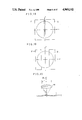
- FIG. 10 shows the diffracted lights E -1 (having center at 0), E +1 (having center at 0 +1 ) and E -1 (having center at 0 -1 ).
- repetition length q of FIG. 8 and FIG. 9 are smaller than 2 ⁇ ( ⁇ is laser light wavelength).
- the distance between the center 0 and center 0 +1 and another distance between center 0 and center 0 -1 are both larger than 1/2f.
- Each diffracted light has similarity with the incident light, and therefore, radii of respective diffracted lights are 1/2f.
- the circle E 0 of FIG. 10 has the same size as the exit pupil, and within a region B therein the diffraction lights E 0 and E +1 interfere with each other; within a region C the diffracted lights E 0 and E -1 interfere with each other. Furthermore, within a region A, only the diffracted light E 0 exists.
- FIG. 10 is a diagram showing change of the reproduced signal amplitude with respect to repetition length q.
- the reflectivities r 1 and r 2 may be complex numbers, and even for such case the similar relation holds.
- the reproduction of the signal is made by each other interference of the reflected diffracted light of 0th order E 0 with reflected diffracted light of +1th order E +1 or -1th order E -1 , and when the interferences are not made (q ⁇ ; that is, the regions B and C in FIG. 10 disappear), the reproduced light is not time-changing, i.e., constant with respect to time.
- the amplitude of the reproduced signal is calculated from the equations (12) and (13) to be 0.186 ( ⁇ R)I 0 , by providing the incident light intensity I 0 as ##EQU12##
- the fundamental principle of using the interference of the diffracted lights in reproducing the signal is the same as the aforementioned elucidation with respect to the U-shaped groove optical disk.
- the signal reproduction is made by making interferences on the exit pupil of the objective lens in a region outside a vertical straight line g, in a manner that diffracted lights E 00 or E 10 having the center on the U axis interfere with upward shifted diffracted lights E 01 or E 11 centers of which has shifted in v axis direction, within the region of the former diffracted light (E 00 or E 10 ).
- the laser spot 22 focussed on the optical disk becomes an ellipse which is longer in the track direction ( ⁇ axis direction) as shown in FIG. 15, and hence the bit density of the recording becomes low. Therefore, the above-mentioned measure can not attain an expected result intended by increasing the track linear velocity thereby failing to reproduce the high frequency signal.
- the incident light beam of elliptic section has its shorter diameter which is 0.5 times the focal length f of the objective lens, and for the simplicity it is provided that it has a uniform light intensity distribution
- the optical light transmission efficiency becomes about 60%, and by presuming that the lasing power of the semiconductor laser to be 25 mW, a light power at maximum of 15 mW can be collected on the disk. Then, by using the TeO x as recording material, by rotating an optical disk of a diameter of 20 cm at a speed of 3600 rpm, recording can be sufficiently made. On the exit pupil of the objective lens 10, as aforementioned the diffracted light has the expansion of the similar figure to the incident light.
- the purpose of the present invention is to provide an improved method for reproduction of optically recorded signal which method is capable of reproducing a higher frequency signal.
- a signal of high frequency can be reproduced and a high quality signal can be handled.
- FIG. 1 is the perspective view showing the surface part of the U-shaped groove type optical disk.
- FIG. 2 is the perspective view showing the surface part of the V-shaped groove type optical disk.
- FIG. 3 is the schematic view illustrating light emitting pattern of the semiconductor laser.
- FIG. 4 is the schematic sectional view showing configuration of the optical system of the general apparatus for reproduction of optically recorded signal.
- FIG. 5 is the schematic front view showing the disposition of the photo-detectors for signal reproduction from the U-shaped groove type optical disk.
- FIG. 6 is the schematic front view showing disposition of the photo-detectors for signal reproduction from the V-shaped groove type optical disk.
- FIG. 7 is the diagram for illustrating principle of signal reproduction from the optical disk.
- FIG. 8 and FIG. 9 are the schematic sectional views for illustrating complex reflectivity distribution of the recorded surface.
- FIG. 10 is the diagram illustrating disposition of diffracted light on the exit pupil of the objective lens of the conventional apparatus.
- FIG. 11 is the frequency characteristic graph of the amplitude of reproduced signal of the conventional apparatus.
- FIG. 12 is the schematic front view illustrating shape of incident light beam for V-shaped groove type optical disk.
- FIG. 13 is the front view illustrating disposition of the diffracted light on the exit pupil of the objective lens at signal reproduction of the V-shaped groove type optical disk.
- FIG. 14 is the front view illustrating shape of the incident light beam for high transmission efficiency.
- FIG. 15 is the front view illustrating shape of the laser spot at the high transmission efficiency.
- FIG. 16 is the front view illustrating disposition of the diffracted lights on the exit pupil face of the objective lens at the high transmission efficiency.
- FIG. 17 is a sectional view illustrating configuration of a first embodiment of optical system of signal reproducing apparatus in accordance with the present invention.
- FIG. 18 is a front view illustrating photo-detectors for signal reproduction from a U-shaped groove type optical disk in accordance with the first embodiment.
- FIG. 19 is a front view illustrating photo-detectors for signal reproduction from a V-shaped groove type optical disk in accordance with the first embodiment.
- FIG. 20 is a sectional view illustrating direction of diffracted light.
- FIG. 21 is a sectional view of prisms 24 in the first embodiment.
- FIG. 22 is a front view illustrating interference region of the first embodiment.
- FIG. 23 is a graph showing frequency characteristic of amplitude of reproduced signal obtained by induced interference in the first embodiment.
- FIG. 24 is a graph showing frequency characteristic of amplitude of reproduced signal obtained in the first embodiment.
- FIG. 25 is a front view showing another embodiment of lenses for collecting diffracted lights coming on paths which do not pass the objective lens 10 in the apparatus of FIG. 17.
- FIG. 26 is a sectional view showing diffracted light guiding means of a second example.
- FIG. 27 is a graph showing frequency characteristic of the amplitude of the reproduced signal of the second embodiment.
- FIG. 28 is a sectional view showing diffracted lights guiding means of a third embodiment.
- FIG. 29 is a sectional view showing optical system of the signal reproduction apparatus of a fourth embodiment.
- FIG. 30 is a front view illustrating interference region of exit pupil of the objective lens 10 of the fourth embodiment.
- FIG. 31 is a front view illustrating disposition of diffracted lights on exit pupil of the objective lens 10 of the fourth embodiment.
- FIG. 32 is a front view illustrating an induced interference region W of the fourth embodiment.
- FIG. 33 is a graph showing frequency characteristic of amplitude of reproduced signal obtained by induced interference in the fourth embodiment.
- FIG. 34 is a graph showing frequency characteristic of amplitude of reproduced signal obtained in the fourth embodiment.
- FIG. 35 is a frequency diagram illustrating video signal amplitude of a high quality television system named MUSE system.
- FIG. 17 A signal reproduction apparatus of a first embodiment of the present invention is shown in FIG. 17.
- a coherent laser light beam X generated by the laser light beam generator 57 shown in FIG. 4 enters from left side.
- the configuration of the laser beam generator 57 is the same or similar as that shown in FIG. 4, and therefore detailed description thereon is omitted.
- the laser light beam X shown by a white arrow passes a known polarized beam splitter 8, a known quarter wave plate 9 and an objective lens 10, and is focussed on a signal recorded surface 11 of an optical recording disk from which travels in a direction v.
- Light reflected by the recorded surface 11 passes through the objective lens 10 and plate 9, and is reflected by the polarized beam splitter 8 and incident to a mirror 25 and a converging lens 27. Another part of reflected light from the recorded surface 11 is collected by a collimator lens 23 and then passes through prisms 24 so as to be made a parallel light beam 102 which is also coherent with the main reflected light beam 101 from the objective lens, and after passing through the quarter wave plate 9, the parallel light beam 102 is reflected by a part of the beam splitter 8, and incident to a half mirror 26.
- the half mirror 26 By the half mirror 26, the light which passes through the objective lens 10, and the mirror 25 is made to interfere with the light which passes through the convex lens 23, the prism 24 and the beam splitter 8, thereby making interference light which is detected by a photo-detector F and G.
- Another part of the returning light 101 which passes through the objective lens 10, the quarter wavelength plate 9 and the beam splitter 8 is converged by a convex lens 27 and reflected by a mirror 28, and the light is focussed on a photo-detector K, so as to be used for automatic focussing control in accordance with known art.
- the photo-detectors F and G are configurated in the same shape and size. The shape and disposition of the photo-detectors F and G with respect to the light beam incident thereon is shown in FIG.
- FIG. 18 which is for the case of a U-shaped groove type optical disk
- FIG. 19 which is for a V-shaped groove type optical disk.
- Control of the tracking is made in the same manner as elucidated in reference to FIGS. 5 and 6.
- the objective lens 10, the convex lens 23 and prisms 24 are encapsulated in an integral casing 200 for easy tracking and focussing controlling.
- Direction of 1st diffracted light fulfills a relation of the following equation for a spacial period q on the recording surface 11 and a wavelength ⁇ of the laser: ##EQU13##
- the objective lens 10 makes parallel coherent light from the incident diffracted light, distance Ob from the optical axis is given as follows:
- the distance of the first diffracted light on the exit pupil from the optical axis is ⁇ f/q.
- the prisms 24 are configurated as shown in FIG. 21, wherein the size in the radial direction of the optical disk is also selected 0.75 f.
- the size, of the reflected light beam in transiential direction (v) of the track is enlarged 2 times as shown in FIG. 22 thereby to become 0.5 f.
- FIG. 22 shows exit pupil of the objective lens. Reflected light of the region Q is collected by the lens 23 and enlarged by the prisms 24 and induced to interfere on the half mirror 26 with the reflected light from the region R of the objective lens 10 of FIG. 22.
- the area of the interference region R is 0.33 f 2 .
- the incident light is uniformly distributed (to have a constant light wave A 0 )
- reflected light in the region Q has a reflected light wave amplitude which is 0.71 times (i.e., ⁇ 1/2) the original one since the beam size is enlarged 2 times, and that the diffracted light wave in the region Q is also uniform and 0.71 A 0 .
- the light wave E QR after interference on the half mirror 26 and light intensity I QR are represented as follows: ##EQU14## Since the area of the region R is 0.33 f 2 , the signal amplitude in the light intensity is 0.095 ( ⁇ R)I 0 .
- the 1st diffracted light is collected by the lens 23, and has the circular expansion with the diameter f in the entrance pupil of the lens 23.
- the 1st diffracted lights interfere with 0th diffracted light in all area of the region R when angle ⁇ of direction of the diffracted light is from 33° to 62°.
- Such range of angle ⁇ corresponds to a range of bit length of the recorded signal from 0.56 ⁇ to 0.91 ⁇ .
- FIG. 23 shows the frequency characteristic of the amplitude of the reproduced signal obtained by interference between the region R and region Q.
- the light in the region B of FIG. 10 has been detected by a photo-detector K, by using the conventional method same as that of FIG. 5.
- the light detection is made by using the light interference between the diffracted lights of the region R and region Q elucidated in FIG. 22. Accordingly, sum of the half amplitude of the signals of FIG. 11 and the amplitude of FIG. 23 becomes the amplitude of reproduced signal of the apparatus of FIG. 17, and the resultant amplitude is shown by a solid curve in FIG. 24, wherein dotted curve shows amplitude of the conventional system of FIG. 11.
- the reproduced signal is slightly smaller than that of the conventional one, for the bit length of less than 0.87 ⁇ , the signal amplitude has sufficient magnitude and the frequency characteristic is much improved than the conventional one.
- the lenses 23 of FIG. 17 is for receiving reflected light for 0.25 f-width in the tangential direction (V), and it corresponds to NA 0.125.
- V tangential direction
- NA 0.125 For such value of NA a single lens constitution can be used without any problem of abberation.
- the apparatus of FIG. 17 has a problem that reflected light must be received for the width of 0.75 f in the radial direction of the optical disk, and this corresponds to NA 0.375, which has a liability of producing an aberration. Therefore, as shown in FIG. 25, by disposing three substantially square lenses having about 0.25 f for both sides in a row as the lens 23, the aberration can be neglected.
- FIG. 26 shows a modified embodiment of the objective lens 10 and prisms 30, 30 disposed around the objective lens as a modified example to be used in place of the adjustable optical lens unit 200 shown in FIG. 17.
- the prisms 30, 30 disposed on both sides in tangential direction of the track of the objective lens 10 are for guiding the reflected diffracted lights from the signal recorded surface to the beam splitter 8 of the apparatus of FIG. 17 and subsequent optical components therein.
- the prisms 30, 30 are to guide the diffracted lights in both positive side and negative side with respect to v axis at the exit pupil of the objective lens, similarly to the 1st embodiment. Accordingly, the amplitude of the reproduced signal becomes 2 times of the value shown in the characteristic diagram of FIG. 23.
- the obtained frequency characteristic is shown in FIG. 27.
- its tracking controlling can be made by using interference light obtained by the half mirror 26 similarly to the case of FIG. 17.
- the focus adjustment can be made by interfering reflected diffracted light in a positive side of the v axis direction at the exit pupil of the objective lens 10 on the half mirror 26, similarly to the case of FIG. 17, and subsequently, after converging the interference light, by detecting it by two divided photo-detectors K, similar to the case of FIG. 17.
- optically recorded signal can be sufficiently reproduced up to such small bit length of 0.55. That is, by using a semiconductor laser having wavelength of 0.83 m, and by rotating the optical disk at 1800 rpm with a radial position of 75 mm for the recorded signal, such a high frequency signal as 15.5 MHz can be reproduced with good quality.
- FIG. 28 is a sectional view showing such embodiment, wherein on both sides of the objective lens 10, a pair of bunches of single mode optical fibers 31, 31 to guide the reflected diffracted light with retaining the coherence are provided. These are encapsulated in an integral casing 200' and used in place of the optical unit 200 of the objective lens of FIG. 17. Other parts and operation are the same as the embodiment 2.
- FIG. 29 shows a fourth embodiment.
- different diffracted lights within the same objective lens 10 are each other interfered.
- the same apparatus 57 as shown in FIG. 1 is used, and therefore the detail of the laser light generation part 57 is omitted.
- Corresponding components and parts to the first embodiment of FIG. 17 are designated by the corresponding numerals thereto and detailed explanation is omitted.
- the light reflected from the recorded surface 11 of the optical disk is guided through one objective lens 10, a quarter wavelength plate 9, a polarized light beam splitter 8 and an optical system having mirrors 34a, 34b, 34c, half mirror 35, a convergence lens 32, a mirror 33 and three photo-detectors F, G and K.
- Upper half part of the reflected light from the objective lens 10 of FIG. 29 is reflected by the beam splitter to the convergence lens 32, and projected on the photo-detector K, the output of which is used to make known focus controlling.
- the output of the photo-detector K may be used for signal reproduction in accordance with the conventional method.
- Lower half part of the reflected light from the objective lens 10 of FIG. 29 is reflected by the lower part of the beam splitter 8 and incident to the mirrors 34b and 34c.
- the light reflected by the mirrors 34b and 34c are made to interfere on the half mirror 35 and the interference lights are detected by the photo-detectors F and G (dispositions of the photo-detectors are the same as described with reference to FIGS. 18 and 19), and the outputs thereof are used both for tracking controlling and signal reproduction in accordance with the principle of the present invention.
- the laser light beam is focussed as shown by FIG. 14 as elliptic laser light beam spot, thereby to achieve high transmission efficiency of the optical system.
- the optical disk having the U-shaped groove and bit density of the fourth embodiment.
- the diffracted lights on the exit pupil of the objective lens 10 do not overlap each other as shown in FIG. 31.
- the diffracted light E 0 and E 1 can be each other interfered, as shown in FIG. 32, wherein the interference region W (shown by hatching) has an area of about 0.15 f 2 .
- the light wave E W in this region W and the light intensity I W are given similarly to the case of equations (10) and (11) as follows: ##EQU15##
- the light wave of the reproduced signal is obtainable as 0.086( ⁇ R)I 0 .
- FIG. 33 shows the frequency characteristic of the amplitude of the reproduced signal in the region W of FIG. 32.
- the frequency characteristic of the amplitude of the reproduced signal in accordance with this embodiment 4 is given as a sum of half value of that of FIG. 11 and that of FIG. 33, and the sum is shown in FIG. 34.
- the bit density is not much different from the conventional method, but it is possible to raise the laser power on the recorded surface 11 of the optical disk, thereby enabling to increase rotation speed of the optical disk.
- the disk is rotated at 3600 rpm, with a radial position of 75 mm for the recorded signal, such a high frequency signal as 18 MHz can be reproduced with good quality.
- the aforementioned MUSE system high quality telvision signal can be represented by showing a spectral distribution of signal shown in FIG. 35, and such high quality TV signal can be recorded and reproduced for a time length of about 10 minutes by using an optical disk having track pitch of 1.67 ⁇ m rotated at about 23 m/sec and having a diameter of 20 cm (radius of recording zone is 5-10 cm).
Landscapes
- Physics & Mathematics (AREA)
- Optics & Photonics (AREA)
- Optical Recording Or Reproduction (AREA)
- Optical Head (AREA)
Applications Claiming Priority (2)
| Application Number | Priority Date | Filing Date | Title |
|---|---|---|---|
| JP60-23869 | 1985-02-08 | ||
| JP60023869A JPH0792916B2 (ja) | 1985-02-08 | 1985-02-08 | 光学記録信号再生方法 |
Related Parent Applications (1)
| Application Number | Title | Priority Date | Filing Date |
|---|---|---|---|
| US06826863 Continuation | 1986-02-06 |
Publications (1)
| Publication Number | Publication Date |
|---|---|
| US4969142A true US4969142A (en) | 1990-11-06 |
Family
ID=12122447
Family Applications (1)
| Application Number | Title | Priority Date | Filing Date |
|---|---|---|---|
| US07/352,651 Expired - Lifetime US4969142A (en) | 1985-02-08 | 1989-05-12 | Reproduction of optically recorded signal |
Country Status (5)
| Country | Link |
|---|---|
| US (1) | US4969142A (de) |
| EP (1) | EP0190698B1 (de) |
| JP (1) | JPH0792916B2 (de) |
| CN (1) | CN1010441B (de) |
| DE (1) | DE3674015D1 (de) |
Cited By (9)
| Publication number | Priority date | Publication date | Assignee | Title |
|---|---|---|---|---|
| US5113386A (en) * | 1989-10-30 | 1992-05-12 | Eastman Kodak Company | Focus and tracking error detector apparatus for optical and magneto-optical information storage systems |
| US5247510A (en) * | 1990-06-29 | 1993-09-21 | Digital Equipment Corporation | Increasing storage density of optical data media by detecting a selected portion of a light spot image corresponding to a single domain |
| US5581532A (en) * | 1990-03-16 | 1996-12-03 | Canon Kabushiki Kaisha | Optical information recording/reproducing apparatus for accurately detecting magnetic domain edges |
| US5663939A (en) * | 1994-05-31 | 1997-09-02 | Asahi Kogaku Kogyo Kabushiki Kaisha | Optical data recording and reproducing apparatus including non-circular beam spot |
| US5712840A (en) * | 1990-03-16 | 1998-01-27 | Canon Kabushiki Kaisha | Optical information recording/reproduciing apparatus having two-division detectors |
| US5757763A (en) * | 1994-07-12 | 1998-05-26 | Massachusetts Institute Of Technology | Optical information storage via amplitude modulation |
| US5784352A (en) * | 1995-07-21 | 1998-07-21 | Massachusetts Institute Of Technology | Apparatus and method for accessing data on multilayered optical media |
| US5841754A (en) * | 1995-12-22 | 1998-11-24 | Samsung Electronics Co., Ltd. | Optical pickup device having an objective lens and auxiliary lenses exterior thereof |
| CN1073733C (zh) * | 1995-08-18 | 2001-10-24 | 三星电子株式会社 | 用于高密度记录/再现的光拾取装置 |
Families Citing this family (2)
| Publication number | Priority date | Publication date | Assignee | Title |
|---|---|---|---|---|
| FR2679059B1 (fr) * | 1991-07-09 | 1993-09-24 | Thomson Csf | Systeme de lecture de disque optique. |
| JP3707812B2 (ja) * | 1994-09-27 | 2005-10-19 | ソニー株式会社 | 光記録方法、光記録装置及び光記録媒体 |
Citations (3)
| Publication number | Priority date | Publication date | Assignee | Title |
|---|---|---|---|---|
| US4349901A (en) * | 1980-06-20 | 1982-09-14 | Eastman Kodak Company | Apparatus and method for reading optical discs |
| US4356392A (en) * | 1979-06-12 | 1982-10-26 | U.S. Philips Corporation | Optical imaging system provided with an opto-electronic detection system for determining a deviation between the image plane of the imaging system and a second plane on which an image is to be formed |
| US4569038A (en) * | 1980-12-19 | 1986-02-04 | Matsushita Electric Industrial Co., Ltd. | Optical disk, high density optical disk system, and high density recording/reproducing method using the optical disk |
Family Cites Families (5)
| Publication number | Priority date | Publication date | Assignee | Title |
|---|---|---|---|---|
| NL7803517A (nl) * | 1978-04-03 | 1979-10-05 | Philips Nv | Registratiedrager met een optisch uitleesbare fase- struktuur en inrichting voor het uitlezen. |
| US4462095A (en) * | 1982-03-19 | 1984-07-24 | Magnetic Peripherals Inc. | Moving diffraction grating for an information track centering system for optical recording |
| JPS5936335A (ja) * | 1982-08-24 | 1984-02-28 | Matsushita Electric Ind Co Ltd | 光デイスク記録再生方法および光デイスク |
| JPS5958637A (ja) * | 1982-09-28 | 1984-04-04 | Sony Corp | 光学式再生装置 |
| JPS59139152A (ja) * | 1983-01-28 | 1984-08-09 | Canon Inc | 光情報再生方法および装置 |
-
1985
- 1985-02-08 JP JP60023869A patent/JPH0792916B2/ja not_active Expired - Lifetime
-
1986
- 1986-01-30 CN CN86100753A patent/CN1010441B/zh not_active Expired
- 1986-02-03 DE DE8686101363T patent/DE3674015D1/de not_active Expired - Lifetime
- 1986-02-03 EP EP86101363A patent/EP0190698B1/de not_active Expired - Lifetime
-
1989
- 1989-05-12 US US07/352,651 patent/US4969142A/en not_active Expired - Lifetime
Patent Citations (3)
| Publication number | Priority date | Publication date | Assignee | Title |
|---|---|---|---|---|
| US4356392A (en) * | 1979-06-12 | 1982-10-26 | U.S. Philips Corporation | Optical imaging system provided with an opto-electronic detection system for determining a deviation between the image plane of the imaging system and a second plane on which an image is to be formed |
| US4349901A (en) * | 1980-06-20 | 1982-09-14 | Eastman Kodak Company | Apparatus and method for reading optical discs |
| US4569038A (en) * | 1980-12-19 | 1986-02-04 | Matsushita Electric Industrial Co., Ltd. | Optical disk, high density optical disk system, and high density recording/reproducing method using the optical disk |
Non-Patent Citations (4)
| Title |
|---|
| "TeOx Thin Films for an Optical Disc Memory", J. Appl. Phys. 54(9), Sep. 1983, Mutsuo Takenaga, et al., pp. 5376-5380. |
| "Thermal Changes of Optical Properties Observed in some Suboxide thin films", J. Appl. Phys. 53(12, Dec. 1982, Takeo Ohta et al., pp. 8497-8500. |
| TeOx Thin Films for an Optical Disc Memory , J. Appl. Phys. 54(9), Sep. 1983, Mutsuo Takenaga, et al., pp. 5376 5380. * |
| Thermal Changes of Optical Properties Observed in some Suboxide thin films , J. Appl. Phys. 53(12, Dec. 1982, Takeo Ohta et al., pp. 8497 8500. * |
Cited By (10)
| Publication number | Priority date | Publication date | Assignee | Title |
|---|---|---|---|---|
| US5113386A (en) * | 1989-10-30 | 1992-05-12 | Eastman Kodak Company | Focus and tracking error detector apparatus for optical and magneto-optical information storage systems |
| US5581532A (en) * | 1990-03-16 | 1996-12-03 | Canon Kabushiki Kaisha | Optical information recording/reproducing apparatus for accurately detecting magnetic domain edges |
| US5712840A (en) * | 1990-03-16 | 1998-01-27 | Canon Kabushiki Kaisha | Optical information recording/reproduciing apparatus having two-division detectors |
| US5247510A (en) * | 1990-06-29 | 1993-09-21 | Digital Equipment Corporation | Increasing storage density of optical data media by detecting a selected portion of a light spot image corresponding to a single domain |
| US5663939A (en) * | 1994-05-31 | 1997-09-02 | Asahi Kogaku Kogyo Kabushiki Kaisha | Optical data recording and reproducing apparatus including non-circular beam spot |
| US5757763A (en) * | 1994-07-12 | 1998-05-26 | Massachusetts Institute Of Technology | Optical information storage via amplitude modulation |
| US5784352A (en) * | 1995-07-21 | 1998-07-21 | Massachusetts Institute Of Technology | Apparatus and method for accessing data on multilayered optical media |
| CN1073733C (zh) * | 1995-08-18 | 2001-10-24 | 三星电子株式会社 | 用于高密度记录/再现的光拾取装置 |
| US5841754A (en) * | 1995-12-22 | 1998-11-24 | Samsung Electronics Co., Ltd. | Optical pickup device having an objective lens and auxiliary lenses exterior thereof |
| CN1074570C (zh) * | 1995-12-22 | 2001-11-07 | 三星电子株式会社 | 光学头装置 |
Also Published As
| Publication number | Publication date |
|---|---|
| EP0190698A1 (de) | 1986-08-13 |
| EP0190698B1 (de) | 1990-09-12 |
| CN1010441B (zh) | 1990-11-14 |
| JPH0792916B2 (ja) | 1995-10-09 |
| DE3674015D1 (de) | 1990-10-18 |
| JPS61182635A (ja) | 1986-08-15 |
| CN86100753A (zh) | 1986-08-27 |
Similar Documents
| Publication | Publication Date | Title |
|---|---|---|
| CA1179059A (en) | Optical disks and recording and reproducing system using the same | |
| US4983017A (en) | Optical head device for reading information stored in a recording medium | |
| US5161139A (en) | Focusing error detecting apparatus | |
| US5737296A (en) | Focus and tracking error detection by using plus and minus first order diffracted light | |
| CA2079620A1 (en) | Holographic elements for an optical recording system | |
| US4969142A (en) | Reproduction of optically recorded signal | |
| JPH08241531A (ja) | 光ピックアップシステム | |
| JPH1055566A (ja) | 光ピックアップ装置 | |
| US4525825A (en) | Method and apparatus for detecting focussing and tracking error signals | |
| JPS60263341A (ja) | 光学ヘツド | |
| US5283778A (en) | Pickup device | |
| US5412635A (en) | Optical disk with signal pit recording format, method of recording same and optical pickup | |
| US5345072A (en) | Focus detection device for reading information from an optical recording medium | |
| US5657307A (en) | Optical data reading apparatus and method | |
| JP2633535B2 (ja) | 光学ピツクアツプ装置 | |
| US5355361A (en) | Optical pickup apparatus for reproducing signals recorded on an optical disk | |
| US5172366A (en) | Optical information reproducing apparatus with selective photodetector output | |
| US5293372A (en) | Apparatus for optically recording and reproducing information from an optical recording medium | |
| US5483508A (en) | Optical recording and reproducing apparatus using a hologram to detect and judge a plurality of pit patterns | |
| PL131561B1 (en) | Apparatus for point-by-point scanning an information carrying surface | |
| US20070041302A1 (en) | Information recording apparatus, and information recording/reproducing apparatus | |
| JPH06101138B2 (ja) | 光ヘツド装置 | |
| US5659534A (en) | Apparatus for reproducing optical information contained disks of various recording densities | |
| KR100242215B1 (ko) | 피트 높이가 다른 광기록매체에 사용할 수 있는 개선된 광학 판독 헤드 | |
| JP2748906B2 (ja) | 光学ヘッド装置 |
Legal Events
| Date | Code | Title | Description |
|---|---|---|---|
| STCF | Information on status: patent grant |
Free format text: PATENTED CASE |
|
| FEPP | Fee payment procedure |
Free format text: PAYOR NUMBER ASSIGNED (ORIGINAL EVENT CODE: ASPN); ENTITY STATUS OF PATENT OWNER: LARGE ENTITY |
|
| FPAY | Fee payment |
Year of fee payment: 4 |
|
| FPAY | Fee payment |
Year of fee payment: 8 |
|
| FPAY | Fee payment |
Year of fee payment: 12 |