EP0190698B1 - Wiedergabe von optisch aufgezeichneten Signalen - Google Patents
Wiedergabe von optisch aufgezeichneten Signalen Download PDFInfo
- Publication number
- EP0190698B1 EP0190698B1 EP86101363A EP86101363A EP0190698B1 EP 0190698 B1 EP0190698 B1 EP 0190698B1 EP 86101363 A EP86101363 A EP 86101363A EP 86101363 A EP86101363 A EP 86101363A EP 0190698 B1 EP0190698 B1 EP 0190698B1
- Authority
- EP
- European Patent Office
- Prior art keywords
- light
- reflected light
- objective lens
- reproduction
- recorded signal
- Prior art date
- Legal status (The legal status is an assumption and is not a legal conclusion. Google has not performed a legal analysis and makes no representation as to the accuracy of the status listed.)
- Expired - Lifetime
Links
- 238000000034 method Methods 0.000 title claims description 10
- 230000003287 optical effect Effects 0.000 claims description 79
- 230000001427 coherent effect Effects 0.000 claims description 8
- 239000013307 optical fiber Substances 0.000 claims description 4
- 230000001678 irradiating effect Effects 0.000 claims description 3
- 230000002093 peripheral effect Effects 0.000 claims 2
- 210000001747 pupil Anatomy 0.000 description 25
- 238000009826 distribution Methods 0.000 description 12
- 238000002310 reflectometry Methods 0.000 description 11
- 239000004065 semiconductor Substances 0.000 description 10
- 230000005540 biological transmission Effects 0.000 description 7
- 238000010586 diagram Methods 0.000 description 6
- 239000011295 pitch Substances 0.000 description 6
- 238000007796 conventional method Methods 0.000 description 5
- 239000000463 material Substances 0.000 description 4
- 230000004075 alteration Effects 0.000 description 3
- 230000003247 decreasing effect Effects 0.000 description 3
- 238000001514 detection method Methods 0.000 description 3
- 229940028444 muse Drugs 0.000 description 3
- GMVPRGQOIOIIMI-DWKJAMRDSA-N prostaglandin E1 Chemical compound CCCCC[C@H](O)\C=C\[C@H]1[C@H](O)CC(=O)[C@@H]1CCCCCCC(O)=O GMVPRGQOIOIIMI-DWKJAMRDSA-N 0.000 description 3
- 230000002452 interceptive effect Effects 0.000 description 2
- 230000007423 decrease Effects 0.000 description 1
- 230000000694 effects Effects 0.000 description 1
- 230000012447 hatching Effects 0.000 description 1
- 230000000737 periodic effect Effects 0.000 description 1
- 102220047090 rs6152 Human genes 0.000 description 1
- 230000035945 sensitivity Effects 0.000 description 1
- 239000007787 solid Substances 0.000 description 1
- 230000003595 spectral effect Effects 0.000 description 1
- 238000009827 uniform distribution Methods 0.000 description 1
Images


Classifications
-
- G—PHYSICS
- G11—INFORMATION STORAGE
- G11B—INFORMATION STORAGE BASED ON RELATIVE MOVEMENT BETWEEN RECORD CARRIER AND TRANSDUCER
- G11B7/00—Recording or reproducing by optical means, e.g. recording using a thermal beam of optical radiation by modifying optical properties or the physical structure, reproducing using an optical beam at lower power by sensing optical properties; Record carriers therefor
- G11B7/004—Recording, reproducing or erasing methods; Read, write or erase circuits therefor
- G11B7/005—Reproducing
-
- G—PHYSICS
- G11—INFORMATION STORAGE
- G11B—INFORMATION STORAGE BASED ON RELATIVE MOVEMENT BETWEEN RECORD CARRIER AND TRANSDUCER
- G11B7/00—Recording or reproducing by optical means, e.g. recording using a thermal beam of optical radiation by modifying optical properties or the physical structure, reproducing using an optical beam at lower power by sensing optical properties; Record carriers therefor
- G11B7/12—Heads, e.g. forming of the optical beam spot or modulation of the optical beam
- G11B7/135—Means for guiding the beam from the source to the record carrier or from the record carrier to the detector
Definitions
- the present invention relates generally to reproduction of optically recorded signal, and particularly concerned with the reproduction of optically recorded signal of high frequency.
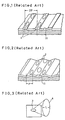
- Fig. 1 schematically shows surface of an optical disk having U-shaped grooves 1 whereon signals are recorded.
- the pitch between the parallel neighboring grooves in order to sufficiently minimize cross-talk from the neighboring grooves, the pitch between the parallel neighboring grooves (track pitch) has to be more than twice the wavelength of the laser light.
- Fig. 2 schematically shows surface of an optical disk having V-shaped grooves 2 on which signals are to be recorded.
- the optical recording disk of Fig. 2 having the V-shaped grooves cross-talk from the neighboring grooves can be minimized even when the pitch between the bottoms the V-shaped grooves are selected to be just twice the wavelength of the laser light. That is, the V-shaped groove type optical disk is capable of storing higher recording density by decreasing track pitches in comparison with those of U-shaped groove type recording disk (M. Nagashima; Applied Physics Letters, Vo. 42, P.144, 1983 or EP-A-55439.
- semiconductor laser which is capable of direct modulation and is small in size
- High power semiconductor laser which can be used for recording the information and has a practically usable life timer, for instance as shown in Fig. 3, has an elliptic light emitting facet 3 and section of the emitted light beam 4 is also of elliptic shape, the wavelength of oscillated light is about 0.8 11m and power of emitted light is around 25 mW.
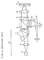
- Fig. 4 shows optical system of the general configuration of an apparatus for recording and reproducing information signal on a disk.
- a light beam emitter part 57 has a semiconductor laser 5 to emit a coherent light, a collimate lens 6 for making the light from the semiconductor laser 5 to a parallel light beam and a beam expander 7 whch expand and reform the collimated beam of the elliptic section to a beam of parallel light of substantially circular section.
- the laser beam X from the light beam emitter part 57 is then led to a polarized beam splitter 8, a quarter plate 9, and focused by an objective lens 10 onto a recorded surface 11 of an optical disk.
- Light reflected from the recorded surface 11 is guided again through the objective lens 10, the quarter plate 9 and the polarized beam splitter 8, and then led through a convex lens 12, from which one part of the reflected light is further reflected by a mirror 13 to irradiate a photo-detector K for focusing control.
- the other part of the light from the convex lens 12 is led to another photo-detector M, and the signals detected by the photo-detectors M are used for reproducing the information and controlling of tracking.
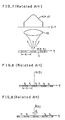
- Shapes of the beam of the reflected light and the light receiving face of the photo-detector M for the system of U-shaped groove optical disk and for the system of V-shaped groove optical disk are shown in Fig. 5 and Fig. 6, respectively. Tracking of the light beam along the U-shaped grooves is made by adjusting the light intensity of the beam 16 received by light detection parts 14 and 15 to become equal each other, and by utilizing signals based on sum of the light intensity on the light detector parts 14 and 15, the signal is reproduced.
- the tracking control is made by slightly wobbling the V-shaped grooves to produce wobble containing output from the light detection parts 17 and 18 followed by extracting signals of the wobbling frequency therefrom EP-A-102799.
- an objective lens of numerical aperture (NA) of 0.5 is used
- an objective lens of numerical aperture (NA) of 0.6 is used in a manner that the laser beam is incident only to a central part of the lens corresponding to NA 0.5.
- the optical disk is rotated at 1800 rpm and the recording is made at a track having 75 mm radius (track linear velocity is 14 m/ sec).
- recording power is 8 mW
- a signal of 10 MHz (recording bit length is 0.7 pm) is obtainable with C/N ratio of about 50 dB (with band width of 30 KHz).
- C/N ratio with band width of 30 KHz
- the V-shaped groove type optical disk can enjoy about twice higher recording density in comparison with the U-shaped groove type one by halving track pitch, but bit densities are the same in both system and the quality of the information to be recorded has no difference each other.
- bit densities are the same in both system and the quality of the information to be recorded has no difference each other.
- description is made hereafter how the bit density is limited by the laser light wavelength or NA of the objective lens.
- orthogonal coordinate (x-y) is provided on an entrance pupil of objective lens 10 for converging laser light on the disk surface, and light wave distribution of the incident laser beam is represented by A (x, y).
- Another orthogonal coordinate ⁇ ⁇ ) is provided on the recording surface 11 of the optical disk.
- axis and ⁇ axis are parallel with x axis and y axis, respectively, and the ⁇ axis is set in radial direction of the optical disk, and n axis is set in the tangential direction of the track of the optical disk.
- Complex reflectivity which gives effects on the reflected light wave of the laser spot is represented as R (E, n).
- the reflected light wave distribution E (u, v) can be represented by the following equation:
- the equation (2) represents the following reflected light from the optical disk consists of many diffracted lights E lm , and each of the diffracted lights has similarity with the incident light A (x, y), and amplitude and phase of the light wave is determined by Fourier series coefficient R, m .
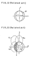
- Fig. 10 shows the diffracted lights E -1 (having center at O), E +1 (having center at 0 +1 ) and E_1) having center at 0 _1 ).
- repetition length q of Fig. 8 and Fig. 9 are smaller than 2 ⁇ ( ⁇ is laser light wavelength). In this case of Fig.
- each diffracted light has similarity to the incident light, and therefore, radii of respective diffracted lights are
- the circle E o of Fig. 10 has the same size as the exit pupil, and within a region B therein the diffraction light E o and E +1 interfere with each other; within a region C the diffracted lights E o and E _1 interfere with each other. Furthermore, within a region A, only the diffracted light E o exists.
- Fig. 10 the light in the region A has no components which change with time.
- Fig. 11 is a diagram showing change of the reproduced signal amplitude with respect to repetition length q.
- the reflectivities r, and r 2 may be complex numbers, and even for such case the similar relation holds.
- the reproduction of the signal is made by each other interference of the reflected diffracted light of Oth order E o with reflected diffracted light of +Ith order E + , or -Ith order E _1 ,and when the interferences are not made (q ⁇ ⁇ ; that is, the regions B and C in Fig. 10 disappear), the reproduced light becomes no time-changing, i.e., constant with respect to time.
- a recording medium of TeO is used and laser light of wavelength 0.83 ⁇ m is used
- the amplitude of the reproduced signal is calculated from the equations (12) and (13) to be 0.186 ( ⁇ R)l o , by providing the incident light intensity l o as
- the fundamental principle of using the interference of the diffracted lights in reproducing the signal is the same as the aforementioned elucidation with respect to the U-shaped groove optical disk.
- the signal reproduction is made by making interferences on the exit pupil of the objective lens in a region outside a vertical straight line g, in a manner that diffracted lights E oo or E, o having the center on the U axis interfere with upward shifted diffracted light E 01 or E 11 centers of which has shifted in v axis direction, within the region of the former diffracted light (E oo or E io ).
- the signal reproduction is made by making interferences on the exit pupil of the objective lens in a region outside a vertical straight line g, in a manner that diffracted lights E oo or E, o having the center on the U axis interfere with upward shifted diffracted light E 01 or E 11 centers of which has shifted in v axis direction, within the region of the former diffracted light (E oo or
- the laser spot 22 focused on the optical disk becomes an ellipse which is longer in the track direction (n axis direction) as shown in Fig. 15, and hence the bit density of the recording becomes low. Therefore, the above-mentioned measure cannot attain an unexpected result intended by increasing the track linear velocity thereby failing to reproduce high frequency signal.
- the incident light beam of elliptic section has its shorter diameter which is 0.5 times of the focal length f of the objective lens, and for the simplicity it is provided that it has a uniform light intensity distribution
- the optical light transmission efficiency becomes about 60%, and by presuming that the lasing power of the semiconductor laser to be 25 mW, a light power at maximum of 15 mW can be collected on the disk. Then, by using the TeD . as recording material, by rotating an optical disk of a diameter of 20 cm at a speed of 3600 rpm, recording can be sufficiently made.
- the diffracted light has the expansion of the similar figure to the incident light.
- the purpose of the present invention is to provide an improved method and apparatus for reproduction of optically recorded signal which method and apparatus are capable of reproducing higher frequency signal.
- signal of high frequency can be reproduced and a high quality signal can be handled.
- Signal reproduction apparatus of a first embodiment of the present invention is shown in Fig. 17.
- a coherent laser light beam X generated by the laser light beam generator 57 shown in Fig. 4 enters from left side.
- the configuration of the laser beam generator 57 is the same or similar as that shown in Fig. 4, and therefore detailed description thereon is omitted.
- the laser light beam X shown by a white arrow passes a known polarized beam splitter 8, a known quarter plate 9 and an objective lens 10, and is focused on a signal recorded surface 11 of an optical recording disk from which travels in a direction v.
- Light reflected by the recorded surface 11 passes through the objective lens and a quarter plate 9, and reflected by the polarized beam splitter 8 and incident to a mirror 25 and a converging lens 27. Another part of reflected light from the recorded surface 11 is collected by a collimator lens 23 and then passes through prisms 24 so as to be made a parallel light beam 102 which is also coherent with the main reflected light beam 101 from the objective lens, and after passing through the quarter plate 9, the parallel light beam 102 is reflected by a part of the beam splitter 8, and incident to a half mirror 26.
- the half mirror 26 By the half mirror 26, the light which passes through the objective lens 10, and the mirror 25 is made to interfere with the light which passes through the convex lens 23, the prism 24 and the beam splitter 8, thereby to make interference light which is detected by a photo-detector F and G.
- Another part of the returning light 101 which passes through the objective lens 10, the quarter wavelength plate 9 and the beam splitter 8 is converted by a convex lens 27 and reflected by a mirror 28, and the light is focused on a photo-detector K, so as to be used for automatic focusing control in accordance with known art.
- the photo-detectors F and G are configurated in the same shape and size. The shape and disposition of the photo-detectors F and G with respect to the light beam incident thereon is shown in Fig.
- Direction of 1st diffracted light fulfills a relation of the following equation for spacial period q on the recording surface 11 and wavelength A of the laser:
- the objective lens 10 makes parallel coherent light from the incident diffracted light, distance Ob from the optical axis is given as follows: As has been described with reference to equation (2), the distance of the first diffracted light on the exit pupil from the optical axis is ⁇ flq.
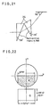
- the prisms 24 are configurated as shown in Fig. 21, wherein the size in the radial direction of the optical disk is also selected 0.75f. After coming out of the two prisms, the size, of the reflected light beam in transiential direction (v) of the track is enlarged 2 times as shown in Fig.
- Fig. 22 shows exit pupil of the objective lens. Reflected light of the region Q is collected by the lens 23 and enlarged by the prisms 24 and induced to interfere on the half mirror 26 with the reflected light from the region R of the objective lens 10 of Fig. 22.
- the area of the interference region R is 0.33f 2.
- the incident light is uniformly distributed (to have a constant light wave A o )
- reflected light in the region Q has a reflected light wave amplitude which is 0.71 times (i.e., v1 ⁇ 2) of the original one since the beam size is enlarged 2 times, and that the diffracted light wave in the region Q is also uniform and 0.71 AO.
- the light wave E QR after interference on the half mirror 26 and light intensity I QR are represented as follows: Since the area of the region R is 0.33f, the signal amplitude in the light intensity is 0.095 ( ⁇ R)l o .
- the 1st diffracted light is collected by the lens 23, and has the circular expansion with the diameter f in the entrance pupil of the lens 23.
- the 1st diffracted lights interfere with Oth diffracted light in all area of the region R when angle a of direction of the diffracted light is from 33° to 62°.
- Such range of angle a corresponds to a range of bit length of the recorded signal from 0.56A to 0.91 ⁇ .
- the Oth diffracted light in the region R has a portion which does not interfere with the 1st diffracted light.
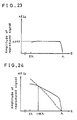
- Fig. 23 shows frequency characteristic of amplitude of reproduced signal obtained by interference between the region R and region Q.
- the light in the region B of Fig. 10 has been detected by a photo-detector K, by using the conventional method same as that of Fig. 5.
- the light detection is made by using the light interference between the diffracted lights of the region R and region Q elucidated in Fig. 22. Accordingly, sum of the half amplitude of the signals of Fig. 11 and the amplitude of Fig. 23 becomes the amplitude of reproduced signal of the apparatus of Fig. 17, and the resultant amplitude is shown by a solid curve in Fig. 24, wherein dotted curve shows amplitude of the conventional system of Fig. 11.
- the reproduced signal is slightly smaller than that of the conventional one, for the bit length of less than 0.87 ⁇ , the signal amplitude has sufficient magnitude and the frequency characteristic is much improved than the conventional one.
- the lenses 23 of Fig. 17 is for receiving reflected light for 0.25f-width in the tangential direction (V), and it corresponds to NA 0.125.
- NA 0.125 For such value of NA a single lens constitution can be used without any problem of aberration.
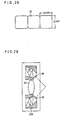
- the apparatus of Fig. 17 has a problem that reflected light must be received for the width of 0.75f in the radial direction of the optical disk, and this corresponds to NA 0.375, which has a liability of producing an aberration. Therefore, as shown in Fig. 25, by disposing three substantially square lenses having about 0.25f for both sides in a row as the lens 23, the aberration can be neglected.
- Fig. 26 shows a modified embodiment of the objective lens 10 and prisms 30, 30 disposed around the objective lens as a modified example to be used in place of the adjustable optical lens unit 200 shown in Fig. 17.
- the prisms 30, 30 disposed on both sides in tangential direction of the track of the objective lens 10 are for guiding the reflected diffracted lights from the signal recorded surface to the beam splitter 8 of the apparatus of Fig. 17 and subsequent optical components therein.
- the prisms 30, 30 are to guide the diffracted lights in both positive side and negative side with respect to v axis at the exit pupil of the objective lens, similarly to the 1st embodiment. Accordingly, the amplitude of the reproduced signal becomes 2 times of the value shown in the characteristic diagram of Fig. 23.
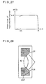
- the obtained frequency characteristic is shown in Fig. 27.
- the tracking controlling can be made by using interference light obtained by the half mirror 26 similarly to the case of Fig. 17.
- the focus adjustment can be made by interfering reflected diffracted light in positive side of the v axis direction at the exit pupil of the objective lens 10 on the half mirror 26, similarly to the case of Fig. 17, and subsequently, after converging the interference light, by detecting it by two divided photo-detectors K, similar to the case of Fig. 17.
- optically recorded signal can be sufficiently reproduced up to such small bit length of 0.55. That is, by using a semiconductor laser having wavelength of 0.83 m, and by rotating the optical disk at 1800 rpm with a radial position of 75 mm for the recorded signal, such a high frequency signal as 15.5 MHz can be reproduced with good quality.
- Fig. 28 is a sectional view showing such embodiment, wherein on both sides of the objective lens 10, a pair of bunches of single mode optical fibers 31, 31 to guide the reflected diffracted light with retaining the coherence are provided. These are encapsulated in an integral casing 200' and is used in place of the optical unit 200 of the objective lens of Fig. 17. Other parts and operation are the same as the embodiment 2.
- Fig. 29 shows a fourth embodiment.
- different diffracted lights within the same objective lens 10 are each other interfered.
- the same apparatus 57 as shown in Fig. 1 is used, and therefore the detail of the laser light generation part 57 is omitted.
- Corresponding components and parts to the first embodiment of Fig. 17 are designated by the corresponding numerals thereto and detailed explanation is omitted.
- the light reflected from the recorded surface 11 of the optical disk is guided through one objective lens 10, a quarter wavelength plate 9, a polarized light beam splitter 8 and an optical system having mirrors 34a, 34b, 34c, half mirror 35, a convergence lens 32, a mirror 33 and three photo-detectors F, G and K.
- Upper half part of the reflected light from the objective lens 10 of Fig. 29 is reflected by the beam splitter to the convergence lens 32, and projected on the photo-detector K, output of which is used to make known focus controlling.
- the output of the photo-detector K may be used for signal reproduction in accordance with the conventional method.
- the laser light beam is focused as shown by Fig. 14 as elliptic laser light beam spot, thereby to achieve high transmission efficiency of the optical system.
- the optical disk having the U-shaped groove and bit density of the fourth embodiment.
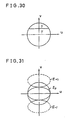
- the diffracted lights on the exit pupil of the objective lens 10 do not each other overlap as shown in Fig. 31.
- the diffracted light E o and E l can be each other interfered, as shown in Fig. 32, wherein the interference region W (shown by hatching) has an area of about 0.15f 2 .
- the light wave E w in this region W and the light intensity l w are given similarly to the case of equations (10) and (11) as follows:
- the light wave of the reproduced signal is obtainable as 0.086( ⁇ R)l o .
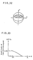
- Fig. 33 shows frequency characteristic of the amplitude of the reproduced signal in the region W of Fig. 32.
- the frequency characteristic of the amplitude of the reproduced signal in accordance with this embodiment 4 is given as a sum of half value of that of Fig. 11 and that of Fig. 33, and the sum is shown in Fig. 34.
- the bit density is not much different from the conventional method, but it is possible to raise the laser power on the recorded surface 11 of the optical disk thereby enabling to increase rotation speed of the optical disk.
- the disk is rotated at 3600 rpm, with a radial posiiton of 75 mm for the recorded signal, such a high frequency signal as 18 MHz can be reproduced with good quality.
- the aforementioned MUSE system high quality television signal can be represented by showing a spectral distribution of signal shown in Fig. 35, and such high quality TV signal can be recorded and reproduced for a time length of about 10 minutes by using an optical disk having track pitch of 1.676 ⁇ m rotated at about 23 m/sec and having a diameter of 20 cm (radius of recording zone is 5-10 cm).
Landscapes
- Physics & Mathematics (AREA)
- Optics & Photonics (AREA)
- Optical Recording Or Reproduction (AREA)
- Optical Head (AREA)
Claims (10)
Applications Claiming Priority (2)
| Application Number | Priority Date | Filing Date | Title |
|---|---|---|---|
| JP23869/85 | 1985-02-08 | ||
| JP60023869A JPH0792916B2 (ja) | 1985-02-08 | 1985-02-08 | 光学記録信号再生方法 |
Publications (2)
| Publication Number | Publication Date |
|---|---|
| EP0190698A1 EP0190698A1 (de) | 1986-08-13 |
| EP0190698B1 true EP0190698B1 (de) | 1990-09-12 |
Family
ID=12122447
Family Applications (1)
| Application Number | Title | Priority Date | Filing Date |
|---|---|---|---|
| EP86101363A Expired - Lifetime EP0190698B1 (de) | 1985-02-08 | 1986-02-03 | Wiedergabe von optisch aufgezeichneten Signalen |
Country Status (5)
| Country | Link |
|---|---|
| US (1) | US4969142A (de) |
| EP (1) | EP0190698B1 (de) |
| JP (1) | JPH0792916B2 (de) |
| CN (1) | CN1010441B (de) |
| DE (1) | DE3674015D1 (de) |
Families Citing this family (11)
| Publication number | Priority date | Publication date | Assignee | Title |
|---|---|---|---|---|
| US5113386A (en) * | 1989-10-30 | 1992-05-12 | Eastman Kodak Company | Focus and tracking error detector apparatus for optical and magneto-optical information storage systems |
| DE69126160T2 (de) * | 1990-03-16 | 1997-10-09 | Canon Kk | Aufzeichnungs-/Wiedergabegerät für optische Information |
| US5712840A (en) * | 1990-03-16 | 1998-01-27 | Canon Kabushiki Kaisha | Optical information recording/reproduciing apparatus having two-division detectors |
| US5247510A (en) * | 1990-06-29 | 1993-09-21 | Digital Equipment Corporation | Increasing storage density of optical data media by detecting a selected portion of a light spot image corresponding to a single domain |
| FR2679059B1 (fr) * | 1991-07-09 | 1993-09-24 | Thomson Csf | Systeme de lecture de disque optique. |
| JPH07326066A (ja) * | 1994-05-31 | 1995-12-12 | Asahi Optical Co Ltd | 光学式情報記録再生装置 |
| US5757763A (en) * | 1994-07-12 | 1998-05-26 | Massachusetts Institute Of Technology | Optical information storage via amplitude modulation |
| JP3707812B2 (ja) * | 1994-09-27 | 2005-10-19 | ソニー株式会社 | 光記録方法、光記録装置及び光記録媒体 |
| WO1997001167A1 (en) * | 1995-06-21 | 1997-01-09 | Massachusetts Institute Of Technology | Apparatus and method for accessing data on multilayered optical media |
| KR0165425B1 (ko) * | 1995-08-18 | 1999-03-20 | 김광호 | 고밀도 기록재생을 위한 광픽업 |
| KR100200868B1 (ko) * | 1995-12-22 | 1999-06-15 | 윤종용 | 광픽업 장치 |
Family Cites Families (8)
| Publication number | Priority date | Publication date | Assignee | Title |
|---|---|---|---|---|
| NL7803517A (nl) * | 1978-04-03 | 1979-10-05 | Philips Nv | Registratiedrager met een optisch uitleesbare fase- struktuur en inrichting voor het uitlezen. |
| NL186353C (nl) * | 1979-06-12 | 1990-11-01 | Philips Nv | Inrichting voor het afbeelden van een maskerpatroon op een substraat voorzien van een opto-elektronisch detektiestelsel voor het bepalen van een afwijking tussen het beeldvlak van een projektielenzenstelsel en het substraatvlak. |
| US4349901A (en) * | 1980-06-20 | 1982-09-14 | Eastman Kodak Company | Apparatus and method for reading optical discs |
| JPS57105828A (en) * | 1980-12-19 | 1982-07-01 | Matsushita Electric Ind Co Ltd | Optical disk recording and reproducing system |
| US4462095A (en) * | 1982-03-19 | 1984-07-24 | Magnetic Peripherals Inc. | Moving diffraction grating for an information track centering system for optical recording |
| JPS5936335A (ja) * | 1982-08-24 | 1984-02-28 | Matsushita Electric Ind Co Ltd | 光デイスク記録再生方法および光デイスク |
| JPS5958637A (ja) * | 1982-09-28 | 1984-04-04 | Sony Corp | 光学式再生装置 |
| JPS59139152A (ja) * | 1983-01-28 | 1984-08-09 | Canon Inc | 光情報再生方法および装置 |
-
1985
- 1985-02-08 JP JP60023869A patent/JPH0792916B2/ja not_active Expired - Lifetime
-
1986
- 1986-01-30 CN CN86100753A patent/CN1010441B/zh not_active Expired
- 1986-02-03 DE DE8686101363T patent/DE3674015D1/de not_active Expired - Lifetime
- 1986-02-03 EP EP86101363A patent/EP0190698B1/de not_active Expired - Lifetime
-
1989
- 1989-05-12 US US07/352,651 patent/US4969142A/en not_active Expired - Lifetime
Also Published As
| Publication number | Publication date |
|---|---|
| EP0190698A1 (de) | 1986-08-13 |
| US4969142A (en) | 1990-11-06 |
| CN1010441B (zh) | 1990-11-14 |
| JPH0792916B2 (ja) | 1995-10-09 |
| DE3674015D1 (de) | 1990-10-18 |
| JPS61182635A (ja) | 1986-08-15 |
| CN86100753A (zh) | 1986-08-27 |
Similar Documents
| Publication | Publication Date | Title |
|---|---|---|
| CA1179059A (en) | Optical disks and recording and reproducing system using the same | |
| JP2740226B2 (ja) | 光走査装置 | |
| KR100543422B1 (ko) | 기록재생장치 및 방법 | |
| US4870508A (en) | Record carrier body with an optical servo track and optical apparatus for writing and reading information from the carrier | |
| US4893298A (en) | Record-carrier body provided with a relief structure of optically detectable servo-track portions and sector addresses and apparatus for forming said structure | |
| EP0354019A2 (de) | Optische Kopfanordnung zum Lesen von in einem Aufzeichnungsmedium gespeicherten Informationen | |
| EP0190698B1 (de) | Wiedergabe von optisch aufgezeichneten Signalen | |
| CA2079620A1 (en) | Holographic elements for an optical recording system | |
| JPH05197962A (ja) | 光ディスク及び光ディスク再生装置 | |
| US5283778A (en) | Pickup device | |
| JPS61172232A (ja) | 予じめ形成された光学的に検出可能なサーボトラツク部分とセクタアドレスを有する記録担体及びこの記録担体構造を記録するための装置 | |
| US5412635A (en) | Optical disk with signal pit recording format, method of recording same and optical pickup | |
| EP0545526B1 (de) | Optisches Abtastgerät | |
| US5483508A (en) | Optical recording and reproducing apparatus using a hologram to detect and judge a plurality of pit patterns | |
| PL131561B1 (en) | Apparatus for point-by-point scanning an information carrying surface | |
| US20070041302A1 (en) | Information recording apparatus, and information recording/reproducing apparatus | |
| KR100242215B1 (ko) | 피트 높이가 다른 광기록매체에 사용할 수 있는 개선된 광학 판독 헤드 | |
| KR100225862B1 (ko) | 환형 셔터 미러와 그 제조방법 및 그를 이용한 이종 광픽업 장치 | |
| JPS6211327B2 (de) | ||
| KR100242216B1 (ko) | 고밀도 디스크용 광학 헤드 | |
| JP2765402B2 (ja) | 光ヘッド装置 | |
| KR100253812B1 (ko) | 고밀도 광디스크용 광픽업 장치 | |
| KR900008379B1 (ko) | 광학식 헤드장치 | |
| KR100266576B1 (ko) | 광픽업 시스템 | |
| JPH11238234A (ja) | 光ディスク記録再生装置の光学ヘッド |
Legal Events
| Date | Code | Title | Description |
|---|---|---|---|
| PUAI | Public reference made under article 153(3) epc to a published international application that has entered the european phase |
Free format text: ORIGINAL CODE: 0009012 |
|
| AK | Designated contracting states |
Kind code of ref document: A1 Designated state(s): DE FR GB |
|
| RIN1 | Information on inventor provided before grant (corrected) |
Inventor name: OBARA, KAZUAKI Inventor name: TAKEMURA, YOSHINARI Inventor name: NAGASHIMA, MICHIYOSHI |
|
| 17P | Request for examination filed |
Effective date: 19870112 |
|
| 17Q | First examination report despatched |
Effective date: 19881121 |
|
| GRAA | (expected) grant |
Free format text: ORIGINAL CODE: 0009210 |
|
| AK | Designated contracting states |
Kind code of ref document: B1 Designated state(s): DE FR GB |
|
| REF | Corresponds to: |
Ref document number: 3674015 Country of ref document: DE Date of ref document: 19901018 |
|
| ET | Fr: translation filed | ||
| PLBE | No opposition filed within time limit |
Free format text: ORIGINAL CODE: 0009261 |
|
| STAA | Information on the status of an ep patent application or granted ep patent |
Free format text: STATUS: NO OPPOSITION FILED WITHIN TIME LIMIT |
|
| 26N | No opposition filed | ||
| REG | Reference to a national code |
Ref country code: GB Ref legal event code: 746 Effective date: 19950224 |
|
| REG | Reference to a national code |
Ref country code: FR Ref legal event code: D6 |
|
| PGFP | Annual fee paid to national office [announced via postgrant information from national office to epo] |
Ref country code: GB Payment date: 19980126 Year of fee payment: 13 |
|
| PGFP | Annual fee paid to national office [announced via postgrant information from national office to epo] |
Ref country code: DE Payment date: 19980206 Year of fee payment: 13 |
|
| PGFP | Annual fee paid to national office [announced via postgrant information from national office to epo] |
Ref country code: FR Payment date: 19980210 Year of fee payment: 13 |
|
| PG25 | Lapsed in a contracting state [announced via postgrant information from national office to epo] |
Ref country code: GB Free format text: LAPSE BECAUSE OF NON-PAYMENT OF DUE FEES Effective date: 19990203 |
|
| GBPC | Gb: european patent ceased through non-payment of renewal fee |
Effective date: 19990203 |
|
| PG25 | Lapsed in a contracting state [announced via postgrant information from national office to epo] |
Ref country code: FR Free format text: LAPSE BECAUSE OF NON-PAYMENT OF DUE FEES Effective date: 19991029 |
|
| PG25 | Lapsed in a contracting state [announced via postgrant information from national office to epo] |
Ref country code: DE Free format text: LAPSE BECAUSE OF NON-PAYMENT OF DUE FEES Effective date: 19991201 |
|
| REG | Reference to a national code |
Ref country code: FR Ref legal event code: ST |