US4968232A - Axial sealing mechanism for a scroll type compressor - Google Patents
Axial sealing mechanism for a scroll type compressor Download PDFInfo
- Publication number
- US4968232A US4968232A US07/342,078 US34207889A US4968232A US 4968232 A US4968232 A US 4968232A US 34207889 A US34207889 A US 34207889A US 4968232 A US4968232 A US 4968232A
- Authority
- US
- United States
- Prior art keywords
- chamber
- scroll
- type compressor
- end plate
- scroll type
- Prior art date
- Legal status (The legal status is an assumption and is not a legal conclusion. Google has not performed a legal analysis and makes no representation as to the accuracy of the status listed.)
- Expired - Lifetime
Links
Images


Classifications
-
- F—MECHANICAL ENGINEERING; LIGHTING; HEATING; WEAPONS; BLASTING
- F04—POSITIVE - DISPLACEMENT MACHINES FOR LIQUIDS; PUMPS FOR LIQUIDS OR ELASTIC FLUIDS
- F04C—ROTARY-PISTON, OR OSCILLATING-PISTON, POSITIVE-DISPLACEMENT MACHINES FOR LIQUIDS; ROTARY-PISTON, OR OSCILLATING-PISTON, POSITIVE-DISPLACEMENT PUMPS
- F04C18/00—Rotary-piston pumps specially adapted for elastic fluids
- F04C18/02—Rotary-piston pumps specially adapted for elastic fluids of arcuate-engagement type, i.e. with circular translatory movement of co-operating members, each member having the same number of teeth or tooth-equivalents
- F04C18/0207—Rotary-piston pumps specially adapted for elastic fluids of arcuate-engagement type, i.e. with circular translatory movement of co-operating members, each member having the same number of teeth or tooth-equivalents both members having co-operating elements in spiral form
- F04C18/0215—Rotary-piston pumps specially adapted for elastic fluids of arcuate-engagement type, i.e. with circular translatory movement of co-operating members, each member having the same number of teeth or tooth-equivalents both members having co-operating elements in spiral form where only one member is moving
-
- F—MECHANICAL ENGINEERING; LIGHTING; HEATING; WEAPONS; BLASTING
- F04—POSITIVE - DISPLACEMENT MACHINES FOR LIQUIDS; PUMPS FOR LIQUIDS OR ELASTIC FLUIDS
- F04C—ROTARY-PISTON, OR OSCILLATING-PISTON, POSITIVE-DISPLACEMENT MACHINES FOR LIQUIDS; ROTARY-PISTON, OR OSCILLATING-PISTON, POSITIVE-DISPLACEMENT PUMPS
- F04C27/00—Sealing arrangements in rotary-piston pumps specially adapted for elastic fluids
- F04C27/005—Axial sealings for working fluid
-
- F—MECHANICAL ENGINEERING; LIGHTING; HEATING; WEAPONS; BLASTING
- F04—POSITIVE - DISPLACEMENT MACHINES FOR LIQUIDS; PUMPS FOR LIQUIDS OR ELASTIC FLUIDS
- F04C—ROTARY-PISTON, OR OSCILLATING-PISTON, POSITIVE-DISPLACEMENT MACHINES FOR LIQUIDS; ROTARY-PISTON, OR OSCILLATING-PISTON, POSITIVE-DISPLACEMENT PUMPS
- F04C23/00—Combinations of two or more pumps, each being of rotary-piston or oscillating-piston type, specially adapted for elastic fluids; Pumping installations specially adapted for elastic fluids; Multi-stage pumps specially adapted for elastic fluids
- F04C23/008—Hermetic pumps
Definitions
- This invention relates to a scroll type compressor, and more particularly, to an axial sealing mechanism for the scroll members of a scroll type compressor.
- FIG. 1 A conventional scroll type compressor with an axial sealing mechanism for axially sealing the scroll members is illustrated in FIG. 1.
- the axial sealing mechanism shown in FIG. 1 is similar to the axial sealing mechanism described in U.S. Pat. No. 4,475,874.
- the scroll type compressor includes fixed scroll 10 having circular end plate 11 from which spiral element 12 extends, and orbiting scroll 20 having circular end plate 21 from which spiral element 22 extends.
- Block member 30 is attached to circular end plate 11 by a plurality of fastening members, such as bolts 31, to define chamber 40 in which orbiting scroll 20 is disposed.
- Spiral elements 12 and 22 are interfitted at an angular and radial offset to make a plurality of line contacts to define at least one pair of sealed-off pockets.
- Driving mechanism 50 which includes rotatably supported drive shaft 51, is connected to orbiting scroll 20 to effect the orbital motion of orbiting scroll 20.
- Oldham coupling 60 is disposed between circular end plate 21 and block member 30 to prevent the rotation of orbiting scroll 20 during its orbital motion.
- Circular end plate 21 of orbiting scroll 20 divides chamber 40 into first chamber 41 in which spiral elements 12 and 22 are disposed and second chamber 42 in which Oldham coupling 60 and one end of driving mechanism 50 are disposed.
- Discharge port 70 is formed at a central portion of circular end plate 11 to discharge the compressed fluid from a central fluid pocket.
- Suction port 80 is formed at a peripheral portion of circular end plate 11 to supply suction fluid to the outermost fluid pockets.
- a pair of apertures 90 which are sized to produce a pressure throttling effect are formed at a middle portion of circular end plate 21 of orbiting scroll 20 to link second chamber 42 to a pair of intermediately compressed fluid pockets 41a.
- the pressure in second chamber 42 which is connected with intermediate fluid pockets 41a by apertures 90, is an average pressure which is related to the range of pressures in intermediate fluid pockets 41a. Accordingly, the axial sealing force applied against orbiting scroll 20 to urge it against fixed scroll 10 is a function of the average intermediate pressure in second chamber 42.
- the axial sealing mechanism of the present invention generates a constant axial force against an end plate of the orbiting scroll to urge it against the fixed scroll to thereby axially seal the scrolls.
- Another object of the present invention is to provide an axial sealing mechanism for a scroll type compressor which is easy and inexpensive to manufacture and does not require high precision machining.
- Another object of the present invention is to provide an axial sealing mechanism for a scroll type compressor that improves the operating efficiency of the compressor.
- a scroll type compressor includes a fixed scroll having a first end plate from which a first spiral element extends and an orbiting scroll having a second end plate from which a second spiral element extends.
- a block member is mounted within the compressor housing and attached to the first end plate to define a chamber in which the orbiting scroll is disposed.
- the first and second spiral elements interfit at an angular and radial offset to make a plurality of line contacts to define at least one pair of sealed-off fluid pockets.
- a discharge space formed within the housing receives compressed fluid discharged from a central fluid pocket defined by the interfitting spiral elements.
- a suction space formed within the housing receives suction fluid and supplies the suction fluid to the outermost fluid pockets defined by the spiral elements.
- a driving mechanism including a rotatable drive shaft is connected to the orbiting scroll to effect the orbital motion of the orbiting scroll.
- a rotation-preventing mechanism for preventing the rotation of the orbiting scroll during its orbital motion is disposed between the block member and the second end plate. The volume of the fluid pockets is changed by the orbital motion of the orbiting scroll.
- the second end plate of the orbiting scroll divides the chamber into a first chamber in which the first and second spiral elements are disposed and a second chamber in which the rotation-preventing mechanism and one end of the drive shaft are disposed.
- a first throttled conduit links the second chamber to the discharge space and second throttled conduit links the second chamber to the suction space.
- FIG. 1 is a vertical sectional view of a conventional scroll type compressor.
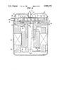
- FIG. 2 is a vertical sectional view of a scroll type compressor in accordance with a first embodiment of the present invention.
- FIG. 3 is a vertical sectional view of a scroll type compressor in accordance with a second embodiment of the present invention.
- FIG. 4 is a vertical sectional view of a scroll type compressor in accordance with a third embodiment of the present invention.
- FIG. 2 A first embodiment of the present invention as applied to a scroll type compressor for use in a refrigerant circuit is illustrated in FIG. 2.
- drive shaft 51 is rotatably supported in bore 31 which is centrally formed in block member 30.
- Bearing 52 is disposed between an outer peripheral surface of drive shaft 51 and an inner peripheral surface of bore 31.
- One end of drive shaft 51 is fixedly attached to bushing 53, which is disposed within second chamber 42.
- Circular boss 23 projects from an end surface opposite spiral element 22 of orbiting scroll 20 and is rotatably inserted into circular depression 531 of bushing 53.
- the center of circular boss 23 is radially offset from the center of drive shaft 51, and circular boss 23 is supported in circular depression 531 by bearing 231.
- Conduit or aperture 71 which is formed in circular end plate 11 of fixed scroll 10, includes first conduit or aperture 71a and second conduit or aperture 71b. These apertures 71a and 71b are sized to produce a pressure throttling effect as further described below.
- First aperture 71a extends radially in circular end plate 11 from an outer peripheral surface of circular end plate 11 to an inner peripheral wall of discharge port 70.
- Second aperature 71b extends axially in circular end plate 11 from first aperture 71a to second chamber 42.
- Plug 72 is fixedly attached to the outer peripheral surface of circular end plate 11 to close the outer radial end of first aperture 71a. Accordingly, aperture 71 links discharge port 70 to second chamber 42.
- Conduit or aperture 81 which is formed in block member 30, includes third conduit or aperture 81a and fourth conduit or aperture 81b. These apertures 81a and 81b also are sized to produce a pressure throttling effect as further described below.
- Third aperature 81a extends radially in block member 30 from an outer peripheral surface of block member 30 to an inner surface of block member 30 which partially defines second chamber 42.
- Fourth aperture 81b extends axially in block member 30 to connect third aperture 81a to suction port 80.
- Plug 82 is fixedly attached to the outer peripheral surface of block member 30 to close the outer radial end of third aperture 81a. Accordingly, aperture 81 links suction port 80 to second chamber 42.
- a portion of the refrigerant gas discharged through discharge port 70 flows into second chamber 42 through aperture 71 at a reduced pressure by virtue of the throttling effect of aperture 71.
- a portion of the refrigerant gas in second chamber 42 also flows into suction port 80 through aperture 81 at a reduced pressure by virtue of the throttling effect of aperture 81.
- the pressure in second chamber 42 which urges orbiting scroll 20 to fixed scroll 10 is maintained at a value which is smaller than the discharge pressure and larger than the suction pressure, that is, an intermediate pressure.
- the pressure in second chamber 42 is maintained at an intermediate pressure with no pressure fluctuation since both the discharge and suction pressures are maintained constant.
- the desired axial sealing pressure (the intermediate pressure) in second chamber 42 can be obtained by selecting the appropriate diameter of apertures 71 and 81. Reduction of the compression capability of the compressor from the discharge gas blown through aperture 71, second chamber 42 and aperture 81 is minimal by virtue of the throttling effect of apertures 71 and 81.
- FIG. 3 illustrates a second embodiment of the present invention applied to a hermetic type scroll compressor for use in a refrigerating circuit.
- fixed scroll 10, orbiting scroll 20, block member 30, driving mechanism 50 and Oldham coupling 60 are housed in hermetically sealed casing 100.
- Casing 100 further houses motor 54 for rotating drive shaft 51.
- Motor 54 includes ring-shaped stator 54a and ring-shaped rotor 54b.
- Stator 54a is firmly secured to an inner peripheral wall of casing 100 by forcible insertion and rotor 54b is firmly secured to drive shaft 51 by forcible insertion.
- Hole 511 is formed in drive shaft 51 to supply lubricating oil 55 collected in the bottom of casing 100 to a gap between an outer peripheral surface of drive shaft 51 and an inner peripheral surface of plain bearing 52.
- radial inlet port 83 which is hermetically sealed to casing 100, is connected to suction port 80.
- Conduit or aperture 711 which is sized to produce a pressure throttling effect, is formed in block member 30 to connect second chamber 42 to inner space 101 of casing 100.
- Conduit or aperture 811 which also is sized to produce a pressure throttling effect, is formed in block member 30 to connect suction port 80 to second chamber 42.
- Aperture 811 includes radial aperture 811a and axial aperture 811b.
- the suction gas is compressed by virtue of the orbital motion of orbiting scroll 20 and then is discharged through discharge port 70.
- this type of hermetic scroll compressor which is generally called a high pressure type hermetic scroll compressor
- the discharged refrigerant gas fills inner space 101 of casing 100 except chamber 40. Only a small portion of the discharged refrigerant gas flows into second chamber 42 through aperture 711 at a reduced pressure due to the throttling effect of aperture 711.
- FIG. 4 illustrates a third embodiment of the present invention, which also is applied to a hermetic type scroll compressor for use in a refrigerating circuit.
- the same numerals are used to denote the corresponding elements shown in FIG. 3, and the explanation of those elements is omitted.
- one end of radial inlet port 83' which is hermetically sealed to casing 100, opens into inner space 101 of casing 100 adjacent suction port 80.
- One end of axial outlet port 73' which is hermetically sealed to casing 100, is connected to discharge port 70.
- Conduit or aperture 712 which is sized to produce a pressure throttling effect, is formed in circular end plate 11 and connects discharge port 70 to second chamber 42.
- Conduit or aperture 712 includes radial aperture 712a and axial aperture 712b.
- Conduit or aperture 812 which also is sized to produce a pressure throttling effect, is formed in block member 30, and connects second chamber 42 to inner space 101 of casing 100.
- the suction gas is compressed by virtue of the orbital motion of orbiting scroll 20 and then is discharged through discharge port 70.
- this type of hermetic scroll compressor which is generally called a low pressure type hermetic scroll compressor, a portion of the suction gas flows into and fills inner space 101 of casing 100 except chamber 40. Only a small portion of the discharged refrigerant gas flows into second chamber 42 through aperture 712 at a reduced pressure.
- the present invention is applied to an hermetic type scroll compressor.
- the construction illustrated in this embodiments can be applied equally in an open type scroll compressor.
- one of the advantages of this invention is that the machining process for forming the apertures need not be precise. Accordingly, improved axial sealing of the scroll elements can be achieved by a simple, easy to manufacture construction which does not adversely affect the overall operation of the scroll compressor.
Landscapes
- Engineering & Computer Science (AREA)
- Mechanical Engineering (AREA)
- General Engineering & Computer Science (AREA)
- Rotary Pumps (AREA)
- Applications Or Details Of Rotary Compressors (AREA)
Applications Claiming Priority (2)
| Application Number | Priority Date | Filing Date | Title |
|---|---|---|---|
| JP63098393A JPH01271680A (ja) | 1988-04-22 | 1988-04-22 | スクロール型圧縮機 |
| JP63-98393 | 1988-04-22 |
Publications (1)
| Publication Number | Publication Date |
|---|---|
| US4968232A true US4968232A (en) | 1990-11-06 |
Family
ID=14218596
Family Applications (1)
| Application Number | Title | Priority Date | Filing Date |
|---|---|---|---|
| US07/342,078 Expired - Lifetime US4968232A (en) | 1988-04-22 | 1989-04-24 | Axial sealing mechanism for a scroll type compressor |
Country Status (7)
| Country | Link |
|---|---|
| US (1) | US4968232A (de) |
| EP (1) | EP0338835B1 (de) |
| JP (1) | JPH01271680A (de) |
| KR (1) | KR0144150B1 (de) |
| AU (1) | AU609601B2 (de) |
| CA (1) | CA1323865C (de) |
| DE (1) | DE68907515T2 (de) |
Cited By (17)
| Publication number | Priority date | Publication date | Assignee | Title |
|---|---|---|---|---|
| US5330335A (en) * | 1991-07-31 | 1994-07-19 | Sanden Corporation | Horizontally oriented rotary machine having internal lubication oil pump |
| US5431550A (en) * | 1993-09-14 | 1995-07-11 | Sanden Corporation | Hermetic motor driven scroll apparatus having improved lubricating mechanism |
| US5520526A (en) * | 1989-10-31 | 1996-05-28 | Matsushita Electric Industrial Co., Ltd. | Scroll compressor with axially biased scroll |
| US5591014A (en) * | 1993-11-29 | 1997-01-07 | Copeland Corporation | Scroll machine with reverse rotation protection |
| US5607288A (en) * | 1993-11-29 | 1997-03-04 | Copeland Corporation | Scroll machine with reverse rotation protection |
| US5678986A (en) * | 1994-10-27 | 1997-10-21 | Sanden Corporation | Fluid displacement apparatus with lubricating mechanism |
| DE19620480A1 (de) * | 1996-05-21 | 1997-11-27 | Bitzer Kuehlmaschinenbau Gmbh | Spiralverdichter |
| US5803716A (en) * | 1993-11-29 | 1998-09-08 | Copeland Corporation | Scroll machine with reverse rotation protection |
| US6015277A (en) * | 1997-11-13 | 2000-01-18 | Tecumseh Products Company | Fabrication method for semiconductor substrate |
| US6086342A (en) * | 1997-08-21 | 2000-07-11 | Tecumseh Products Company | Intermediate pressure regulating valve for a scroll machine |
| US6267565B1 (en) | 1999-08-25 | 2001-07-31 | Copeland Corporation | Scroll temperature protection |
| CN1082147C (zh) * | 1996-09-20 | 2002-04-03 | 株式会社日立制作所 | 容积型流体机械 |
| US6379131B1 (en) * | 1999-03-04 | 2002-04-30 | Sanden Corporation | Scroll type compressor |
| US6416301B2 (en) * | 2000-06-16 | 2002-07-09 | Scroll Technologies | Scroll compressor with axially floating non-orbiting scroll and no separator plate |
| US6821092B1 (en) | 2003-07-15 | 2004-11-23 | Copeland Corporation | Capacity modulated scroll compressor |
| US20070036661A1 (en) * | 2005-08-12 | 2007-02-15 | Copeland Corporation | Capacity modulated scroll compressor |
| CN105805001A (zh) * | 2016-05-12 | 2016-07-27 | 广东美的暖通设备有限公司 | 涡旋压缩机和空调器 |
Families Citing this family (9)
| Publication number | Priority date | Publication date | Assignee | Title |
|---|---|---|---|---|
| JPH039094A (ja) * | 1989-06-02 | 1991-01-16 | Sanden Corp | スクロール型圧縮機 |
| CA2081080C (en) * | 1992-10-23 | 1998-08-11 | Philippe Gaultier | Method for the detection of reciprocating machine faults and failures |
| US5562435A (en) * | 1994-04-20 | 1996-10-08 | Lg Electronics, Inc. | Structure for preventing axial leakage in a scroll compressor |
| JP4517444B2 (ja) * | 2000-03-31 | 2010-08-04 | 株式会社日立製作所 | スクロール圧縮機 |
| JP2003013872A (ja) * | 2001-06-28 | 2003-01-15 | Toyota Industries Corp | スクロール型圧縮機およびスクロール型圧縮機の冷媒圧縮方法 |
| JP4697734B2 (ja) * | 2005-01-14 | 2011-06-08 | 日立アプライアンス株式会社 | 冷凍サイクル |
| US7472005B2 (en) * | 2005-07-25 | 2008-12-30 | Ephraim Ubon B | Auxiliary steering system for vehicles |
| DE102015120151A1 (de) | 2015-11-20 | 2017-05-24 | OET GmbH | Verdrängermaschine nach dem Spiralprinzip, Verfahren zum Betreiben einer Verdrängermaschine, Fahrzeugklimaanlage und Fahrzeug |
| DE102017110913B3 (de) | 2017-05-19 | 2018-08-23 | OET GmbH | Verdrängermaschine nach dem Spiralprinzip, Verfahren zum Betreiben einer Verdrängermaschine, Fahrzeugklimaanlage und Fahrzeug |
Citations (12)
| Publication number | Priority date | Publication date | Assignee | Title |
|---|---|---|---|---|
| US3884599A (en) * | 1973-06-11 | 1975-05-20 | Little Inc A | Scroll-type positive fluid displacement apparatus |
| US4332535A (en) * | 1978-12-16 | 1982-06-01 | Sankyo Electric Company Limited | Scroll type compressor having an oil separator and oil sump in the suction chamber |
| US4475874A (en) * | 1977-01-14 | 1984-10-09 | Hitachi, Ltd. | Scroll fluid apparatus with axial sealing force |
| US4527963A (en) * | 1982-09-30 | 1985-07-09 | Sanden Corporation | Scroll type compressor with lubricating system |
| JPS60166779A (ja) * | 1984-02-09 | 1985-08-30 | Matsushita Refrig Co | スクロ−ル型圧縮機 |
| US4538975A (en) * | 1983-08-16 | 1985-09-03 | Sanden Corporation | Scroll type compressor with lubricating system |
| JPS60178789A (ja) * | 1984-02-25 | 1985-09-12 | Shoichi Tanaka | 固体エリアセンサの信号発生方法 |
| JPS60224987A (ja) * | 1984-04-20 | 1985-11-09 | Daikin Ind Ltd | スクロ−ル形圧縮機 |
| JPS60228788A (ja) * | 1984-04-26 | 1985-11-14 | Daikin Ind Ltd | スクロール圧縮機 |
| JPS60228787A (ja) * | 1984-04-25 | 1985-11-14 | Daikin Ind Ltd | スクロ−ル形流体機械 |
| US4561832A (en) * | 1983-03-14 | 1985-12-31 | Sanden Corporation | Lubricating mechanism for a scroll-type fluid displacement apparatus |
| JPS62168986A (ja) * | 1986-01-20 | 1987-07-25 | Matsushita Electric Ind Co Ltd | スクロ−ル気体圧縮機 |
-
1988
- 1988-04-22 JP JP63098393A patent/JPH01271680A/ja active Pending
-
1989
- 1989-04-20 EP EP89303944A patent/EP0338835B1/de not_active Expired - Lifetime
- 1989-04-20 DE DE89303944T patent/DE68907515T2/de not_active Expired - Fee Related
- 1989-04-21 KR KR1019890005248A patent/KR0144150B1/ko not_active Expired - Fee Related
- 1989-04-24 AU AU33352/89A patent/AU609601B2/en not_active Ceased
- 1989-04-24 CA CA000597625A patent/CA1323865C/en not_active Expired - Fee Related
- 1989-04-24 US US07/342,078 patent/US4968232A/en not_active Expired - Lifetime
Patent Citations (12)
| Publication number | Priority date | Publication date | Assignee | Title |
|---|---|---|---|---|
| US3884599A (en) * | 1973-06-11 | 1975-05-20 | Little Inc A | Scroll-type positive fluid displacement apparatus |
| US4475874A (en) * | 1977-01-14 | 1984-10-09 | Hitachi, Ltd. | Scroll fluid apparatus with axial sealing force |
| US4332535A (en) * | 1978-12-16 | 1982-06-01 | Sankyo Electric Company Limited | Scroll type compressor having an oil separator and oil sump in the suction chamber |
| US4527963A (en) * | 1982-09-30 | 1985-07-09 | Sanden Corporation | Scroll type compressor with lubricating system |
| US4561832A (en) * | 1983-03-14 | 1985-12-31 | Sanden Corporation | Lubricating mechanism for a scroll-type fluid displacement apparatus |
| US4538975A (en) * | 1983-08-16 | 1985-09-03 | Sanden Corporation | Scroll type compressor with lubricating system |
| JPS60166779A (ja) * | 1984-02-09 | 1985-08-30 | Matsushita Refrig Co | スクロ−ル型圧縮機 |
| JPS60178789A (ja) * | 1984-02-25 | 1985-09-12 | Shoichi Tanaka | 固体エリアセンサの信号発生方法 |
| JPS60224987A (ja) * | 1984-04-20 | 1985-11-09 | Daikin Ind Ltd | スクロ−ル形圧縮機 |
| JPS60228787A (ja) * | 1984-04-25 | 1985-11-14 | Daikin Ind Ltd | スクロ−ル形流体機械 |
| JPS60228788A (ja) * | 1984-04-26 | 1985-11-14 | Daikin Ind Ltd | スクロール圧縮機 |
| JPS62168986A (ja) * | 1986-01-20 | 1987-07-25 | Matsushita Electric Ind Co Ltd | スクロ−ル気体圧縮機 |
Cited By (18)
| Publication number | Priority date | Publication date | Assignee | Title |
|---|---|---|---|---|
| US5520526A (en) * | 1989-10-31 | 1996-05-28 | Matsushita Electric Industrial Co., Ltd. | Scroll compressor with axially biased scroll |
| US5330335A (en) * | 1991-07-31 | 1994-07-19 | Sanden Corporation | Horizontally oriented rotary machine having internal lubication oil pump |
| US5431550A (en) * | 1993-09-14 | 1995-07-11 | Sanden Corporation | Hermetic motor driven scroll apparatus having improved lubricating mechanism |
| US5803716A (en) * | 1993-11-29 | 1998-09-08 | Copeland Corporation | Scroll machine with reverse rotation protection |
| US5591014A (en) * | 1993-11-29 | 1997-01-07 | Copeland Corporation | Scroll machine with reverse rotation protection |
| US5607288A (en) * | 1993-11-29 | 1997-03-04 | Copeland Corporation | Scroll machine with reverse rotation protection |
| US5678986A (en) * | 1994-10-27 | 1997-10-21 | Sanden Corporation | Fluid displacement apparatus with lubricating mechanism |
| DE19620480C2 (de) * | 1996-05-21 | 1999-10-21 | Bitzer Kuehlmaschinenbau Gmbh | Spiralverdichter |
| DE19620480A1 (de) * | 1996-05-21 | 1997-11-27 | Bitzer Kuehlmaschinenbau Gmbh | Spiralverdichter |
| CN1082147C (zh) * | 1996-09-20 | 2002-04-03 | 株式会社日立制作所 | 容积型流体机械 |
| US6086342A (en) * | 1997-08-21 | 2000-07-11 | Tecumseh Products Company | Intermediate pressure regulating valve for a scroll machine |
| US6015277A (en) * | 1997-11-13 | 2000-01-18 | Tecumseh Products Company | Fabrication method for semiconductor substrate |
| US6379131B1 (en) * | 1999-03-04 | 2002-04-30 | Sanden Corporation | Scroll type compressor |
| US6267565B1 (en) | 1999-08-25 | 2001-07-31 | Copeland Corporation | Scroll temperature protection |
| US6416301B2 (en) * | 2000-06-16 | 2002-07-09 | Scroll Technologies | Scroll compressor with axially floating non-orbiting scroll and no separator plate |
| US6821092B1 (en) | 2003-07-15 | 2004-11-23 | Copeland Corporation | Capacity modulated scroll compressor |
| US20070036661A1 (en) * | 2005-08-12 | 2007-02-15 | Copeland Corporation | Capacity modulated scroll compressor |
| CN105805001A (zh) * | 2016-05-12 | 2016-07-27 | 广东美的暖通设备有限公司 | 涡旋压缩机和空调器 |
Also Published As
| Publication number | Publication date |
|---|---|
| AU3335289A (en) | 1989-10-26 |
| EP0338835B1 (de) | 1993-07-14 |
| DE68907515T2 (de) | 1993-12-09 |
| EP0338835A2 (de) | 1989-10-25 |
| JPH01271680A (ja) | 1989-10-30 |
| EP0338835A3 (en) | 1990-04-25 |
| KR0144150B1 (ko) | 1998-08-01 |
| KR890016296A (ko) | 1989-11-28 |
| DE68907515D1 (de) | 1993-08-19 |
| AU609601B2 (en) | 1991-05-02 |
| CA1323865C (en) | 1993-11-02 |
Similar Documents
| Publication | Publication Date | Title |
|---|---|---|
| US4968232A (en) | Axial sealing mechanism for a scroll type compressor | |
| US4932845A (en) | Scroll type compressor with lubrication in suction chamber housing | |
| AU606786B2 (en) | Scroll type compressor | |
| US4936756A (en) | Hermetic scroll type compressor with refrigerant fluid flow through the drive shaft | |
| US5342183A (en) | Scroll compressor with discharge diffuser | |
| US5312234A (en) | Scroll compressor formed of three sub-assemblies | |
| US5931650A (en) | Hermetic electric scroll compressor having a lubricating passage in the orbiting scroll | |
| EP0107409B1 (de) | Kompressor der Spiralbauart mit Schmiersystem | |
| EP0479421A1 (de) | Spiralverdichter mit schwimmender Abdichtung | |
| EP2205873A1 (de) | Verdichter mit einem absperrventil | |
| AU1671601A (en) | Scroll compressor | |
| US4561832A (en) | Lubricating mechanism for a scroll-type fluid displacement apparatus | |
| JP4057915B2 (ja) | オイル注入継手を有する水平スクロール式圧縮機 | |
| EP0400951B1 (de) | Axialdichtungseinrichtung für Spiralverdichter | |
| JP2003013872A (ja) | スクロール型圧縮機およびスクロール型圧縮機の冷媒圧縮方法 | |
| US5474431A (en) | Scroll machine having discharge port inserts | |
| US6179591B1 (en) | Conical hub bearing for scroll machine | |
| EP0743454B1 (de) | Spiralverdrängungsanlage für Fluid | |
| EP0539239A1 (de) | Motor-Fluidverdichter | |
| US5431550A (en) | Hermetic motor driven scroll apparatus having improved lubricating mechanism | |
| EP0468238B1 (de) | Spiralverdichter mit Einrichtung zur variablen Verdrängung | |
| US5660538A (en) | Suction mechanism of a fluid displacement apparatus | |
| JPH0374588A (ja) | スクロール形流体機械のスイングリンク | |
| US6336798B1 (en) | Rotation preventing mechanism for scroll-type fluid displacement apparatus | |
| JP3217959B2 (ja) | スクロール型流体装置 |
Legal Events
| Date | Code | Title | Description |
|---|---|---|---|
| AS | Assignment |
Owner name: SANDEN CORPORATION, JAPAN Free format text: ASSIGNMENT OF ASSIGNORS INTEREST.;ASSIGNOR:KIKUCHI, KAZUTO;REEL/FRAME:005093/0898 Effective date: 19890519 |
|
| STCF | Information on status: patent grant |
Free format text: PATENTED CASE |
|
| FPAY | Fee payment |
Year of fee payment: 4 |
|
| FPAY | Fee payment |
Year of fee payment: 8 |
|
| FPAY | Fee payment |
Year of fee payment: 12 |
|
| REMI | Maintenance fee reminder mailed |