US4965875A - Flourescent lamp - Google Patents
Flourescent lamp Download PDFInfo
- Publication number
- US4965875A US4965875A US07/123,063 US12306388A US4965875A US 4965875 A US4965875 A US 4965875A US 12306388 A US12306388 A US 12306388A US 4965875 A US4965875 A US 4965875A
- Authority
- US
- United States
- Prior art keywords
- sleeve
- fluorescent lamp
- accordance
- housing
- fluorescent
- Prior art date
- Legal status (The legal status is an assumption and is not a legal conclusion. Google has not performed a legal analysis and makes no representation as to the accuracy of the status listed.)
- Expired - Fee Related
Links
- 238000009429 electrical wiring Methods 0.000 claims description 3
- 238000002347 injection Methods 0.000 claims description 3
- 239000007924 injection Substances 0.000 claims description 3
- 238000004519 manufacturing process Methods 0.000 description 2
- 239000000428 dust Substances 0.000 description 1
- 230000005611 electricity Effects 0.000 description 1
- 238000009877 rendering Methods 0.000 description 1
Images

Classifications
-
- H—ELECTRICITY
- H01—ELECTRIC ELEMENTS
- H01J—ELECTRIC DISCHARGE TUBES OR DISCHARGE LAMPS
- H01J61/00—Gas-discharge or vapour-discharge lamps
- H01J61/02—Details
-
- F—MECHANICAL ENGINEERING; LIGHTING; HEATING; WEAPONS; BLASTING
- F21—LIGHTING
- F21S—NON-PORTABLE LIGHTING DEVICES; SYSTEMS THEREOF; VEHICLE LIGHTING DEVICES SPECIALLY ADAPTED FOR VEHICLE EXTERIORS
- F21S8/00—Lighting devices intended for fixed installation
- F21S8/03—Lighting devices intended for fixed installation of surface-mounted type
- F21S8/033—Lighting devices intended for fixed installation of surface-mounted type the surface being a wall or like vertical structure, e.g. building facade
- F21S8/035—Lighting devices intended for fixed installation of surface-mounted type the surface being a wall or like vertical structure, e.g. building facade by means of plugging into a wall outlet, e.g. night light
-
- F—MECHANICAL ENGINEERING; LIGHTING; HEATING; WEAPONS; BLASTING
- F21—LIGHTING
- F21V—FUNCTIONAL FEATURES OR DETAILS OF LIGHTING DEVICES OR SYSTEMS THEREOF; STRUCTURAL COMBINATIONS OF LIGHTING DEVICES WITH OTHER ARTICLES, NOT OTHERWISE PROVIDED FOR
- F21V15/00—Protecting lighting devices from damage
- F21V15/01—Housings, e.g. material or assembling of housing parts
-
- F—MECHANICAL ENGINEERING; LIGHTING; HEATING; WEAPONS; BLASTING
- F21—LIGHTING
- F21V—FUNCTIONAL FEATURES OR DETAILS OF LIGHTING DEVICES OR SYSTEMS THEREOF; STRUCTURAL COMBINATIONS OF LIGHTING DEVICES WITH OTHER ARTICLES, NOT OTHERWISE PROVIDED FOR
- F21V17/00—Fastening of component parts of lighting devices, e.g. shades, globes, refractors, reflectors, filters, screens, grids or protective cages
-
- F—MECHANICAL ENGINEERING; LIGHTING; HEATING; WEAPONS; BLASTING
- F21—LIGHTING
- F21V—FUNCTIONAL FEATURES OR DETAILS OF LIGHTING DEVICES OR SYSTEMS THEREOF; STRUCTURAL COMBINATIONS OF LIGHTING DEVICES WITH OTHER ARTICLES, NOT OTHERWISE PROVIDED FOR
- F21V21/00—Supporting, suspending, or attaching arrangements for lighting devices; Hand grips
- F21V21/02—Wall, ceiling, or floor bases; Fixing pendants or arms to the bases
-
- F—MECHANICAL ENGINEERING; LIGHTING; HEATING; WEAPONS; BLASTING
- F21—LIGHTING
- F21Y—INDEXING SCHEME ASSOCIATED WITH SUBCLASSES F21K, F21L, F21S and F21V, RELATING TO THE FORM OR THE KIND OF THE LIGHT SOURCES OR OF THE COLOUR OF THE LIGHT EMITTED
- F21Y2103/00—Elongate light sources, e.g. fluorescent tubes
Definitions
- the invention relates to a fluorescent lamp having a fluorescent tube and a connecting element for connection to a source of current.
- fluorescent lamps are being used more and more because fluorescent lamps have greater longevity and consume less energy.
- fluorescent lamps it is, moreover, also possible to easily achieve desired texture of light, especially light comparable to daylight, while incandescent lighting is characterized by a yellowish hue and lower luminous efficiency which is often inadequate for purposes of illuminating working areas. For this reason, therefore, it is common, especially in working areas, and principally in large surface working areas, such as industrial office spaces, large-scale culinary facilities and the like, to install fluorescent lamps which usually take the form of banks of permanently installed overhead lighting running along the ceiling.
- the task to be resolved by the invention is to develop a fluorescent lamp which can be easily and firmly connected to the power supply in the various parts of a building.
- a fluorescent lamp which is characterized by a connecting element which is shaped into a housing enclosing the fluorescent tube.
- the connecting element is preferably so configured that it both supplies the electrical power to the fluorescent lamp and, when plugged in, provides adequate support, thereby rendering additional means of support unnecessary.
- the connecting element can, for example, be a screw-in base which can be screwed into a lamp socket which functions as the electrical power source.
- the connecting element can also be a cable lead or any kind of connector with contact plugs.
- the connecting element has the form of a mains plug with contact plugs which are connected to the fluorescent tube in an electrically conductive way and which project on one side, and the area of the mains plug which faces the contact plugs is shaped as a housing.
- An advantage of the fluorescent lamp the subject of the invention is that it can plugged into an electric outlet usually available in any room.
- the fluorescent lamp By being plugged into the outlet, the fluorescent lamp is both connected to the power mains and firmly held in place in the outlet since an area of the contact plug is shaped as a housing and encloses the fluorescent tube.
- the fluorescent lamp is immediately ready for use, and additional supports on the fluorescent lamp, on the walls or ceilings of the room in which the lamp is used, are thus eliminated to advantage.
- the contact plug has the form of a flat plug, also called a Euro-plug, so that it will fit any kind of electric outlet, in particular, when traveling, an outlet conforming to different electrical standards, e.g., in a hotel room.
- a flat plug also called a Euro-plug
- the housing in a preferred embodiment, assumes the shape of the fluorescent tube and is oblong and the mains plug is located on the longitudinal side of the housing, projecting Vertically from this longitudinal side such that minimum mechanical forces act on the contact plugs and mains plug which give the fluorescent lamp its firm support when it is plugged into the outlet.
- the housing is approximately 17 cm in length, about 4 cm wide and 2 cm high.
- the housing preferably consists of two separable half-shells.
- both half-shells are identically shaped so that they are interchangeable.
- the contact plugs are preferably arranged in the junction plane of both half-shells so they, and other parts of the mains plug are accessible when the housing is opened up. Injection molded half-shells, preferably made of plastic, can be especially cost-effectively produced.
- both half-shells which make up the housing are easily united by joining the two halves together, which halves have internal notched elements which, when the housing is assembled, engage the matching notched elements of the corresponding other half-shell.
- the interior space of the housing has the form of two contiguous sleeves which extend in a direction parallel to each other.
- the first sleeve houses the fluorescent tube; the second, the electrical wiring needed to operate the fluorescent tube, and the mains plug is tip-stretched on the longitudinal edge of the second sleeve which faces away from the first sleeve.
- the fluorescent tube and the wiring required to operate the fluorescent tube can be compactly and easily accomodated in, and removed for replacement from, both sleeves which extend in a direction parallel to each other.
- the housing has preferably only approximately double the volume of the fluorescent lamp tube, thus making the fluorescent lamp handy in size and so lightweight of its ownself that it rests firmly connected in and to the outlet.
- the mains plug is tip-stretched on the second sleeve which contains the wiring, such that short contacts enable the contact plugs to make electrical contact with the wiring and the fluorescent lamp tube points away from the electrical outlet and in the direction of the room to be lighted when the fluorescent lamp is plugged in.
- first sleeve has been adapted to fit the fluorescent lamp so that the fluorescent tube can be inserted into this first sleeve and is held in the first sleeve without slack.
- the first sleeve has a recess in its side which serves as a window for the fluorescent lamp tube, which recess preferably stretches over the entire central wall area of the first sleeve.
- the recess is covered with a covering or an insert, made of translucent plastic, for example, to protect the fluorescent lamp and its connecting contacts against dust.
- the second sleeve opens out into chambers which border the front sides of the first sleeve on the outside of the first sleeve and contact vanes, providing frontal connecting contacts for the fluorescent tube, are arranged in the first sleeve, which contacts are connected to the wiring housed in the second in an electrically conductive way.
- the contact vanes are so arranged on the front sides of the first sleeve, that the fluorescent lamp tube makes electrical contact via its connecting contacts with the mains plug as soon as the fluorescent lamp tube is inserted into the first sleeve without its having to be connected by means of clamp connectors or similar devices.
- guides may be provided in the first sleeve for the fluorescent tube's connecting contacts so that the fluorescent lamp tube can only be inserted into the first sleeve in a position in which the connecting contacts sit snugly against the contact vanes.
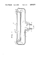
- FIG. 1 top view of a half-shell of a housing according to the invention
- FIG. 2 a cross-section of the half-shell according to FIG. 1, along the dash-dotted line in FIG. 1 identified by II--II and
- FIG. 3 a partial section side view of the half-shell according to FIG. 1 and FIG. 2.
- FIG. 1 shows a top view of a half-shell 1, which together with a second, identical half-shell 1 can form a connecting element which is shaped into a housing which supports a fluorescent lamp tube 5.
- Both half-shells 1 have notched male and female elements 2a, 2b, by means of which the shells can be joined together.
- the interior of the housing formed by both half-shells 1 is shaped like sleeves 3, 4, which extend in a direction parallel to each other.
- the fluorescent lamp tube 5 is inserted into the first sleeve 3, the tube having connecting contacts 6 which snugly rest against electrical contact vanes 7 provided on the front sides 8 of the first sleeve 3 and which vanes establish electrical conductive contact with the electric wiring (not shown) housed in the second sleeve 4.
- the second sleeve 4 opens out into chambers which border the front sides of the first sleeve, through which chambers the contact vanes 7 establish electrical contact with the wiring housed in the second sleeve 4.
- the connecting element passes over the longitudinal edge of the second sleeve 4 which edge faces away from the first sleeve 3 into the housing and in the practical example shown this connecting element has the form of a (power supply or light socket plug) 11 from which contact plugs 12 project, which contact plugs are connected via the leads 13 indicated in an electrically conductive way to the wiring housed in the second sleeve 4 and by means of which contact plugs said wiring is supplied with electricity when the contact plugs 12 are plugged into an electrical outlet.
- a (power supply or light socket plug) 11 from which contact plugs 12 project, which contact plugs are connected via the leads 13 indicated in an electrically conductive way to the wiring housed in the second sleeve 4 and by means of which contact plugs said wiring is supplied with electricity when the contact plugs 12 are plugged into an electrical outlet.
- FIG. 2 shows a cross-section of the half-shell 1 according to FIG. 1. Identical parts components are identified by the same reference numbers used in FIG. 1.
- FIG. 2 the interior configuration of the housing which has the shape of two parallel sleeves 3, 4 can be particularly noted.
- the notched male elements 2a on the sleeve 1 can be observed, which elements project out over the junction plane of both half-shells 1.
- the contact plugs 12 located in the junction plane can also be observed.
- the fluorescent lamp tube 5 is indicated by a dash-dotted circle.
- FIG. 3 shows a side view of the half-shell 1 according to FIG. 1 and 2, which side view is shown in partial section. Identical parts components are again identified with the same reference numbers as in the preceding figures.
Abstract
Description
Claims (19)
Applications Claiming Priority (2)
| Application Number | Priority Date | Filing Date | Title |
|---|---|---|---|
| DE19863603264 DE3603264A1 (en) | 1986-02-03 | 1986-02-03 | FLUORESCENT LAMP LAMP WITH A FLUORESCENT LAMP |
| DE3603264 | 1986-02-03 |
Publications (1)
| Publication Number | Publication Date |
|---|---|
| US4965875A true US4965875A (en) | 1990-10-23 |
Family
ID=6293264
Family Applications (1)
| Application Number | Title | Priority Date | Filing Date |
|---|---|---|---|
| US07/123,063 Expired - Fee Related US4965875A (en) | 1986-02-03 | 1987-01-31 | Flourescent lamp |
Country Status (9)
| Country | Link |
|---|---|
| US (1) | US4965875A (en) |
| EP (1) | EP0233529B1 (en) |
| JP (1) | JP2545425B2 (en) |
| KR (1) | KR880700911A (en) |
| AT (1) | ATE62537T1 (en) |
| DE (3) | DE3603264A1 (en) |
| ES (1) | ES2021614B3 (en) |
| GR (1) | GR3002278T3 (en) |
| WO (1) | WO1987004771A1 (en) |
Cited By (4)
| Publication number | Priority date | Publication date | Assignee | Title |
|---|---|---|---|---|
| US5111370A (en) * | 1991-02-21 | 1992-05-05 | Clark Walter B | Device and method for converting a down-light into an up-light |
| US5649759A (en) * | 1995-03-03 | 1997-07-22 | Korte; Heinrich | Lamp for fluorescent tubes |
| US6060838A (en) * | 1995-11-21 | 2000-05-09 | Creative Concepts And Consulting Corporation | Illumination device |
| US20110090682A1 (en) * | 2009-10-15 | 2011-04-21 | Fu Zhun Precision Industry (Shen Zhen) Co., Ltd. | Led tube |
Families Citing this family (5)
| Publication number | Priority date | Publication date | Assignee | Title |
|---|---|---|---|---|
| DE9000730U1 (en) * | 1990-01-24 | 1990-03-29 | Korte Gmbh, 2951 Filsum, De | |
| NL9301649A (en) * | 1993-09-24 | 1995-04-18 | Massive Productie Nederland B | Lamp |
| DE59307651D1 (en) * | 1993-11-20 | 1997-12-11 | Heinrich Korte | Luminaire for fluorescent tubes |
| EP0677699A1 (en) * | 1994-03-04 | 1995-10-18 | Heinrich Korte | Fluorescent lamp mounting |
| DE19900889B4 (en) * | 1999-01-12 | 2004-04-15 | Suresh Hiralal Shah | Kit for converting luminaires with straight fluorescent lamps with a base on both sides, from inductive to electronic operation |
Citations (22)
| Publication number | Priority date | Publication date | Assignee | Title |
|---|---|---|---|---|
| US2227739A (en) * | 1937-08-21 | 1941-01-07 | John H Pollard | Combined bracket and lighting device |
| US2871455A (en) * | 1954-11-18 | 1959-01-27 | Norman H Richardson | Electrical fixture |
| US3283144A (en) * | 1964-05-15 | 1966-11-01 | Cons Electronic Equipment Comp | Portable light |
| GB1106929A (en) * | 1965-07-02 | 1968-03-20 | Victor Products Ltd | Improvements relating to lighting fittings |
| US3819923A (en) * | 1973-02-06 | 1974-06-25 | Gen Electric | Seal off around ge3952 lamp |
| GB1398521A (en) * | 1971-06-04 | 1975-06-25 | Merchant Adventurers Ltd | Lighting fittings |
| US3908120A (en) * | 1974-06-18 | 1975-09-23 | Preformed Line Products Co | Rotational collar alignment device |
| US4045665A (en) * | 1975-06-25 | 1977-08-30 | Preformed Line Products Co. | Diffuser attachment for a fluorescent lamp fixture |
| US4130860A (en) * | 1976-05-04 | 1978-12-19 | Wabco Westinghouse | Fluorescent lamp support assemblage with built-in converter for the lighting of vehicles |
| DE2853379A1 (en) * | 1977-12-13 | 1979-06-21 | Philips Nv | LAMP |
| EP0012234A1 (en) * | 1978-12-13 | 1980-06-25 | Patent-Treuhand-Gesellschaft für elektrische Glühlampen mbH | Fluorescent lighting fixture |
| DE3014640A1 (en) * | 1980-04-16 | 1981-10-29 | Patent-Treuhand-Gesellschaft für elektrische Glühlampen mbH, 8000 München | RING SHAPED FLUORESCENT LAMP WITH INTEGRATED SWITCHING AND IGNITION DEVICE |
| EP0054595A1 (en) * | 1980-12-22 | 1982-06-30 | S.A Clarel | Watertight lighting fitting for tubular lamps |
| DE3100920A1 (en) * | 1981-01-14 | 1982-08-05 | Heinrich Steinel KG, 4836 Herzebrock | ORIENTATION LAMP |
| DE8331193U1 (en) * | 1983-10-29 | 1984-02-16 | Güç, Ficret, 7000 Stuttgart | LIGHT, IN PARTICULAR HAND LAMP |
| US4443050A (en) * | 1979-06-13 | 1984-04-17 | Strix Limited | Electrical interconnectors |
| US4460947A (en) * | 1983-04-07 | 1984-07-17 | Mcgraw-Edison | Light fixture housing including snap latch |
| FR2539485A1 (en) * | 1983-01-14 | 1984-07-20 | Conte Daniel | Handlamp with fluorescent tube, with a fitment/holder for a removable tube |
| US4477863A (en) * | 1982-02-25 | 1984-10-16 | Alfred Walz | Work-light |
| DE3325840A1 (en) * | 1983-07-18 | 1985-01-31 | Patent-Treuhand-Gesellschaft für elektrische Glühlampen mbH, 8000 München | LAMP FOR A FLUORESCENT LAMP |
| EP0151674A2 (en) * | 1984-01-09 | 1985-08-21 | Brillantleuchten AG | Domestic and/or work lamp |
| DE3542076A1 (en) * | 1984-12-06 | 1986-06-19 | Hartmut 5828 Ennepetal Brocke | Emitter |
Family Cites Families (7)
| Publication number | Priority date | Publication date | Assignee | Title |
|---|---|---|---|---|
| DE1716385U (en) * | 1955-11-28 | 1956-02-09 | Bela Lampenfabrik Albert Becke | FLUORESCENT LAMP WITH SCREW SOCKET. |
| DE1987800U (en) * | 1967-04-05 | 1968-06-20 | Fred Schramm | PLUG WITH LAMP HOLDER. |
| DE1979227U (en) * | 1967-12-13 | 1968-02-22 | Karl-Eberhard Voigt | PLUG-IN LIGHT. |
| SE383791B (en) * | 1968-09-12 | 1976-03-29 | Seeburg Corp | VARUAUTOMAT |
| JPS51146791U (en) * | 1975-05-19 | 1976-11-25 | ||
| JPS55111101U (en) * | 1979-01-31 | 1980-08-05 | ||
| JPS5774905A (en) * | 1981-08-29 | 1982-05-11 | Matsushita Electric Works Ltd | Miniature equipment built in electronic circuit |
-
1986
- 1986-02-03 DE DE19863603264 patent/DE3603264A1/en not_active Withdrawn
- 1986-02-03 DE DE8602756U patent/DE8602756U1/de not_active Expired
-
1987
- 1987-01-31 JP JP62500978A patent/JP2545425B2/en not_active Expired - Lifetime
- 1987-01-31 EP EP87101328A patent/EP0233529B1/en not_active Expired - Lifetime
- 1987-01-31 AT AT87101328T patent/ATE62537T1/en not_active IP Right Cessation
- 1987-01-31 DE DE8787101328T patent/DE3769163D1/en not_active Expired - Lifetime
- 1987-01-31 US US07/123,063 patent/US4965875A/en not_active Expired - Fee Related
- 1987-01-31 ES ES87101328T patent/ES2021614B3/en not_active Expired - Lifetime
- 1987-01-31 WO PCT/DE1987/000039 patent/WO1987004771A1/en unknown
- 1987-09-22 KR KR1019870700933A patent/KR880700911A/en not_active Application Discontinuation
-
1991
- 1991-07-09 GR GR91400981T patent/GR3002278T3/en unknown
Patent Citations (22)
| Publication number | Priority date | Publication date | Assignee | Title |
|---|---|---|---|---|
| US2227739A (en) * | 1937-08-21 | 1941-01-07 | John H Pollard | Combined bracket and lighting device |
| US2871455A (en) * | 1954-11-18 | 1959-01-27 | Norman H Richardson | Electrical fixture |
| US3283144A (en) * | 1964-05-15 | 1966-11-01 | Cons Electronic Equipment Comp | Portable light |
| GB1106929A (en) * | 1965-07-02 | 1968-03-20 | Victor Products Ltd | Improvements relating to lighting fittings |
| GB1398521A (en) * | 1971-06-04 | 1975-06-25 | Merchant Adventurers Ltd | Lighting fittings |
| US3819923A (en) * | 1973-02-06 | 1974-06-25 | Gen Electric | Seal off around ge3952 lamp |
| US3908120A (en) * | 1974-06-18 | 1975-09-23 | Preformed Line Products Co | Rotational collar alignment device |
| US4045665A (en) * | 1975-06-25 | 1977-08-30 | Preformed Line Products Co. | Diffuser attachment for a fluorescent lamp fixture |
| US4130860A (en) * | 1976-05-04 | 1978-12-19 | Wabco Westinghouse | Fluorescent lamp support assemblage with built-in converter for the lighting of vehicles |
| DE2853379A1 (en) * | 1977-12-13 | 1979-06-21 | Philips Nv | LAMP |
| EP0012234A1 (en) * | 1978-12-13 | 1980-06-25 | Patent-Treuhand-Gesellschaft für elektrische Glühlampen mbH | Fluorescent lighting fixture |
| US4443050A (en) * | 1979-06-13 | 1984-04-17 | Strix Limited | Electrical interconnectors |
| DE3014640A1 (en) * | 1980-04-16 | 1981-10-29 | Patent-Treuhand-Gesellschaft für elektrische Glühlampen mbH, 8000 München | RING SHAPED FLUORESCENT LAMP WITH INTEGRATED SWITCHING AND IGNITION DEVICE |
| EP0054595A1 (en) * | 1980-12-22 | 1982-06-30 | S.A Clarel | Watertight lighting fitting for tubular lamps |
| DE3100920A1 (en) * | 1981-01-14 | 1982-08-05 | Heinrich Steinel KG, 4836 Herzebrock | ORIENTATION LAMP |
| US4477863A (en) * | 1982-02-25 | 1984-10-16 | Alfred Walz | Work-light |
| FR2539485A1 (en) * | 1983-01-14 | 1984-07-20 | Conte Daniel | Handlamp with fluorescent tube, with a fitment/holder for a removable tube |
| US4460947A (en) * | 1983-04-07 | 1984-07-17 | Mcgraw-Edison | Light fixture housing including snap latch |
| DE3325840A1 (en) * | 1983-07-18 | 1985-01-31 | Patent-Treuhand-Gesellschaft für elektrische Glühlampen mbH, 8000 München | LAMP FOR A FLUORESCENT LAMP |
| DE8331193U1 (en) * | 1983-10-29 | 1984-02-16 | Güç, Ficret, 7000 Stuttgart | LIGHT, IN PARTICULAR HAND LAMP |
| EP0151674A2 (en) * | 1984-01-09 | 1985-08-21 | Brillantleuchten AG | Domestic and/or work lamp |
| DE3542076A1 (en) * | 1984-12-06 | 1986-06-19 | Hartmut 5828 Ennepetal Brocke | Emitter |
Cited By (4)
| Publication number | Priority date | Publication date | Assignee | Title |
|---|---|---|---|---|
| US5111370A (en) * | 1991-02-21 | 1992-05-05 | Clark Walter B | Device and method for converting a down-light into an up-light |
| US5649759A (en) * | 1995-03-03 | 1997-07-22 | Korte; Heinrich | Lamp for fluorescent tubes |
| US6060838A (en) * | 1995-11-21 | 2000-05-09 | Creative Concepts And Consulting Corporation | Illumination device |
| US20110090682A1 (en) * | 2009-10-15 | 2011-04-21 | Fu Zhun Precision Industry (Shen Zhen) Co., Ltd. | Led tube |
Also Published As
| Publication number | Publication date |
|---|---|
| DE3769163D1 (en) | 1991-05-16 |
| JPH01500470A (en) | 1989-02-16 |
| EP0233529B1 (en) | 1991-04-10 |
| KR880700911A (en) | 1988-04-13 |
| WO1987004771A1 (en) | 1987-08-13 |
| ES2021614B3 (en) | 1991-11-16 |
| DE8602756U1 (en) | 1988-02-11 |
| EP0233529A1 (en) | 1987-08-26 |
| GR3002278T3 (en) | 1992-12-30 |
| ATE62537T1 (en) | 1991-04-15 |
| DE3603264A1 (en) | 1987-08-06 |
| JP2545425B2 (en) | 1996-10-16 |
Similar Documents
| Publication | Publication Date | Title |
|---|---|---|
| US5662408A (en) | Simple plug in night light having a low profile | |
| US20060039168A1 (en) | Modular luminaire system | |
| US4965875A (en) | Flourescent lamp | |
| US5169227A (en) | Fluorescent lamp | |
| US6162096A (en) | Reflector assembly socket which accepts a PL lamp | |
| US20180292055A1 (en) | Modular lighting system | |
| EP0997990A3 (en) | Connection configuration of a multiple-light lighting fixture | |
| US20030090903A1 (en) | Lighting fixture and system | |
| WO2005001333A3 (en) | Floodlight and spotlight adapter and enclosure | |
| CN209116055U (en) | A kind of connection structure and the lamps and lanterns including the connection structure | |
| ATE331184T1 (en) | LAMP HOLDER MADE OF INSULATING MATERIAL FOR H 7 LAMPS | |
| EP0829676A1 (en) | Light bulb and decorative lighting system using same | |
| CN102324658A (en) | Outdoor socket with lamps | |
| CN213513431U (en) | Serial-type cupboard lamp | |
| CN217978522U (en) | Cupboard lamp and lighting system convenient to wiring | |
| DE50112566D1 (en) | LAMP | |
| CN214580928U (en) | Movable joint structure for lamp body capable of being freely split and combined | |
| CN211118848U (en) | Ultra-thin portable bar lamp | |
| AU593777B2 (en) | A connector | |
| KR200224392Y1 (en) | Ligting Fixtures | |
| KR950008071Y1 (en) | Lamp device | |
| CN109442251A (en) | A kind of connection structure and the lamps and lanterns including the connection structure | |
| JPH0441522Y2 (en) | ||
| KR830002085Y1 (en) | Lampshade | |
| KR840002138Y1 (en) | Sooket |
Legal Events
| Date | Code | Title | Description |
|---|---|---|---|
| AS | Assignment |
Owner name: KORTE-LICHT, GROSSWOLDER STRASSE 60-62, 2957 IHRHO Free format text: ASSIGNMENT OF ASSIGNORS INTEREST.;ASSIGNOR:KORTE, HEINRICH;REEL/FRAME:004831/0551 Effective date: 19880205 Owner name: KORTE-LICHT,GERMANY Free format text: ASSIGNMENT OF ASSIGNORS INTEREST;ASSIGNOR:KORTE, HEINRICH;REEL/FRAME:004831/0551 Effective date: 19880205 |
|
| FPAY | Fee payment |
Year of fee payment: 4 |
|
| FPAY | Fee payment |
Year of fee payment: 8 |
|
| REMI | Maintenance fee reminder mailed | ||
| LAPS | Lapse for failure to pay maintenance fees | ||
| STCH | Information on status: patent discontinuation |
Free format text: PATENT EXPIRED DUE TO NONPAYMENT OF MAINTENANCE FEES UNDER 37 CFR 1.362 |
|
| FP | Lapsed due to failure to pay maintenance fee |
Effective date: 20021023 |