US4952186A - Method of making a color picture tube electron gun with reduced convergence drift - Google Patents
Method of making a color picture tube electron gun with reduced convergence drift Download PDFInfo
- Publication number
- US4952186A US4952186A US07/427,275 US42727589A US4952186A US 4952186 A US4952186 A US 4952186A US 42727589 A US42727589 A US 42727589A US 4952186 A US4952186 A US 4952186A
- Authority
- US
- United States
- Prior art keywords
- electrodes
- electrode
- electron gun
- misconvergence
- thermal expansion
- Prior art date
- Legal status (The legal status is an assumption and is not a legal conclusion. Google has not performed a legal analysis and makes no representation as to the accuracy of the status listed.)
- Expired - Lifetime
Links
Images


Classifications
-
- H—ELECTRICITY
- H01—ELECTRIC ELEMENTS
- H01J—ELECTRIC DISCHARGE TUBES OR DISCHARGE LAMPS
- H01J9/00—Apparatus or processes specially adapted for the manufacture, installation, removal, maintenance of electric discharge tubes, discharge lamps, or parts thereof; Recovery of material from discharge tubes or lamps
-
- H—ELECTRICITY
- H01—ELECTRIC ELEMENTS
- H01J—ELECTRIC DISCHARGE TUBES OR DISCHARGE LAMPS
- H01J29/00—Details of cathode-ray tubes or of electron-beam tubes of the types covered by group H01J31/00
- H01J29/46—Arrangements of electrodes and associated parts for generating or controlling the ray or beam, e.g. electron-optical arrangement
- H01J29/48—Electron guns
- H01J29/484—Eliminating deleterious effects due to thermal effects, electrical or magnetic fields; Preventing unwanted emission
-
- H—ELECTRICITY
- H01—ELECTRIC ELEMENTS
- H01J—ELECTRIC DISCHARGE TUBES OR DISCHARGE LAMPS
- H01J29/00—Details of cathode-ray tubes or of electron-beam tubes of the types covered by group H01J31/00
- H01J29/46—Arrangements of electrodes and associated parts for generating or controlling the ray or beam, e.g. electron-optical arrangement
- H01J29/48—Electron guns
- H01J29/50—Electron guns two or more guns in a single vacuum space, e.g. for plural-ray tube
- H01J29/503—Three or more guns, the axes of which lay in a common plane
Definitions
- This invention relates to color picture tubes having multibeam electron guns and particularly, to an improved method of making such guns having reduced convergence drift of the electron beams during tube warmup.
- An inline electron gun is one designed to generate or initiate preferably three electron beams in a common plane and direct those beams along convergent paths in that plane, to a point or small area of convergence at the tube screen.
- Inline electron guns attain static convergence of the undeflected electron beams by slightly distorting the focus fields at the outer beams, so that the outer beams are deflected toward the center beam to effect convergence of the beams at the screen.
- One means of distorting the focus fields is to offset one aperture in a focus electrode from its associated aperture in a facing focus electrode.
- a given static convergence at the screen of a tube is established by a particular combination of aperture offsets throughout the gun and beam position in the main lens.
- a problem, encountered in color picture tubes having built-in static convergence is convergence drift during tube warm-up. Convergence drift is caused by a change of beam position in the main lens due to a relative change of horizontal aperture positions of all the electrodes throughout the electron gun. The relative aperture motion is caused by different thermal expansions of the different grids due to a temperature gradient from the cathode to the main lens.
- the present invention provides an improvement in a method of making a color picture tube electron gun that includes the selection and assembly of a plurality of cathodes and a plurality of electrodes longitudinally spaced from the cathodes.
- the improvement comprises at least three additional steps. First, the amount and direction of electron beam misconvergence at the tube screen, as caused by the thermal expansion of each individual electrode during electron gun warmup, is determined. A first group of electrodes will cause misconvergence in a first direction, and a second group of electrodes will cause misconvergence in a second direction. Second, the individual contributions of the electrodes to misconvergence during tube warmup are summed. The net effect of thermal expansion of the entire electron gun is a misconvergence in the first direction. Third, at least one of the electrodes in the first group of electrodes is formed from a material having a lower coefficient of thermal expansion than the coefficient of thermal expansion used in the first step of determining misconvergence caused by the thermal expansion of each individual electrode.
- FIG. 1 is a plan view, partly in axial section, of a shadow mask color picture tube embodying the invention.
- FIG. 2 is a side view of the electron gun shown in dashed lines in FIG. 1.
- FIG. 3 is an axial section view of a simplified version of the electron gun shown in FIG. 2.
- FIG. 4 is a graph showing convergence drift versus time of a standard unmodified electron gun of the type shown in FIG. 2.
- FIG. 5 is a graph of electrode temperature versus time during tube warmup.
- FIG. 6 is a graph of electron beam motion versus time for each electrode of the electron gun of FIG. 2.
- FIG. 7 is a graph, similar to the graph of FIG. 6, with the curves normalized to converge at the end of the tube warmup time.
- FIG. 8 is a graph, similar to the graph of FIG. 7, showing the convergence drift between two outer beams, red and blue.
- FIG. 9 is a graph showing the combined convergence drift between outer electron beams, red and blue, for all of the electron gun electrodes.
- FIG. 10 is a graph of the combined convergence drift between outer electron beams in a standard unmodified electron gun, a gun with a low expansion G2 electrode, a gun with a low expansion G4 electrode and a gun with combined low expansion G2 and G4 electrodes.
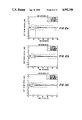
- FIG. 11a, 11b and 11c are graphs of convergence drift curves for three different tubes having low expansion G2 electrodes.
- FIGS. 12a, 12b and 12c are graphs of convergence drift curves for three different tubes having low expansion G4 electrodes.
- FIGS. 13a, 13b and 13c are graphs of convergence drift curves for three different tubes having combined low expansion G2 and G4 electrodes.
- FIG. 14 is a composite graph comparing the outer-to-outer beam convergence drift in tubes having a standard unmodified gun, a gun with a low expansion G2, a gun with a low expansion G4 and a gun with combined low expansion G2 and G4 electrodes.
- FIG. 1 is a plan view of a rectangular color picture tube 10 having a glass envelope comprising a rectangular faceplate panel or cap 12 and a tubular neck 14 connected by a rectangular funnel 16.
- the panel comprises a viewing faceplate 18 and a peripheral flange or sidewall 20 which is sealed to the funnel 16.
- a three-color phosphor screen 22 is carried by the inner surface of the faceplate 18.
- the screen is preferably a line screen with the phosphor lines extending substantially perpendicular to the high frequency raster line scan of the tube (normal to the plane of FIG. 1).
- a multi-apertured color-selection electrode or shadow mask 24 is removably mounted in predetermined spaced relation to the screen 22.
- An improved inline electron gun 26, shown schematically by dotted lines in FIG. 1, is centrally mounted within the neck 14 to generate and direct three electron beams 28 along coplanar convergent paths through the mask 24 to the screen 22.
- the tube of FIG. 1 is designed to be used with an external magnetic deflection yoke, such as the self-converging yoke 30 shown surrounding the neck 14 and funnel 12 in the neighborhood of their junction.
- the yoke 30 subjects the three beams 28 to vertical and horizontal magnetic fields which cause the beams to scan horizontally and vertically, respectively, in a rectangular raster over the screen 22.
- the initial plane of deflection (at zero deflection) is shown by the line P-P in FIG. 1 at about the middle of the yoke 30. Because of fringe fields, the zone of deflection of the tube extends axially, from the yoke 30 into the region of the electron gun 26. For simplicity, the actual curvature of the deflected beam paths in the deflection zone is not shown in FIG. 1.
- the details of the electron gun 26 are shown in FIGS. 2 and 3.
- the electron gun comprises two glass supports rods 32 on which various electrodes are mounted. These electrodes include three equally spaced coplanar cathodes 34 (one for each beam), a G1 grid electrode 36, a G2 grid electrode 38, a G3 electrode 40, a G4 electrode 42, a G5 electrode 44, and a G6 electrode 46, spaced along the glass rods 32 in the order named. All of the post-cathode electrodes have three inline apertures therein to permit passage of three coplanar electron beams.
- the G1 grid electrode 36 and the G2 grid electrode 38 are parallel flat plates that can include embossings therein, e.g., for added strength.
- the G3 electrode 40 is formed by two cup-shaped elements 60 and 62, each having apertured bottoms.
- the apertured bottom of the element 60 faces the G2 grid electrode 38, and the open end of the element 60 is attached to the open end of the element 62.
- the G4 electrode 42 is a plate having three apertures 61 (one shown) therein.
- the G5 electrode 44 is formed with two cup-shaped elements 68 and 70.
- the closed ends of the elements 68 and 70 include each three apertures, and the open ends of the elements 68 and 70 are connected.
- the G6 electrode 46 also includes two cup-shaped elements 72 and 73 having apertured bottoms.
- a shield cup 75 is attached to the outside bottom of the element 73.
- the facing closed ends of the G5 electrode 44 and the G6 electrode 46 have large recesses 76 and 78, respectively, therein.
- the recesses 76 and 78 set back a portion of the closed end of the G5 electrode 44 that contains three apertures 82 (one shown) from a portion of the closed end of the G6 electrode 46 that contains three apertures 88 (one shown).
- the remaining portions of the closed ends of the G5 electrode 44 and the G6 electrode 46 form rims 92 and 94, respectively, that extend peripherally around the recesses 76 and 78.
- the rims 92 and 94 are the closest portions of the two electrodes 44 and 46 to each other.
- the configuration of the recess 78 in the G6 electrode 46 is different from that of the recess 76 in the G5 electrode 44.
- the recess 78 is narrower at the center aperture than at the side apertures, whereas the recess 76 is uniform in width at the three apertures therein.
- the G4 electrode 42 is electrically connected by a lead 96 to the G2 electrode 38, and the G3 electrode 40 is electrically connected by a lead 98 to the G5 electrode 44, as shown in FIG. 3.
- Separate leads connect the G3 electrode 40, the G2 electrode 38, the G1 electrode 36, the cathodes 34 and the cathode heaters to a base 100 (shown in FIG. 1) of the tube 10, so that these components can be electrically activated.
- Electrical activation of the G6 electrode 46 is obtained by a contact between the shield cup 75 and an internal conductive coating in the tube which is electrically connected to an anode button extending through the funnel 16. (The coating and anode button are not shown.)
- the cathodes 34, the G1 electrode 36 and the G2 electrode 38 comprise the beam-forming region of the gun.
- modulated control voltages are applied to the cathodes 34, the G1 electrode 36 is electrically grounded, and a relatively low positive voltage (e.g., 800 to 1100 volts) is applied to the G2 electrode 38.
- the G3 electrode 40, the G4 electrode 42, and the facing portion of the G5 electrode 44 comprise a prefocusing lens portion of the electron gun 26.
- a focus voltage is applied to both the G3 electrode 40 and to the G5 electrode 44.
- the facing portions of the G5 electrode 44 and the G6 electrode 46 comprise the main focus lens of the electron gun 26.
- an anode voltage is applied to the G6 electrode 46, so that a bipotential focus lens is formed between the G5 and G6 electrodes.
- the G1 electrode 36, the G2 electrode 38 and the G4 electrode 42 are constructed of a material or materials having lower coefficients of thermal expansion than do the materials used to construct the other electrodes.
- the G1 electrode 36, the G2 electrode 38 and the G4 electrode 42 are made from 430 stainless steel, which is a magnetically permeable material.
- the bottom portion or G2-facing side of the G3 electrode 40 is made from a 52% nickel alloy which is also magnetically permeable.
- the top portion of the G3 electrode 40, the G5 electrode 44 and the G6 electrode 46 are made from 305 stainless steel, which is nonmagnetic. The purpose and results of using these materials of different coefficients of thermal expansion are discussed below.
- the convergence drift of a standard unmodified electron gun of the same type as disclosed in FIG. 2 is shown in FIG. 4.
- the drift between the blue and red beams does not decrease to less than 0.1 mm until about 20 minutes.
- the improved electron gun was designed by analyzing the motion of each electrode in the gun during tube warmup and then by determining the sensitivity of electron beam motion to the horizontal motion of the apertures in each electrode. Once this sensitivity was established, it was then determined how to alter the aperture motion of selected electrodes, to reduce convergence drift, through the use of different thermal expansion materials.
- the horizontal positions of the outer apertures in each electrode were independently changed in 0.002 inch (0.05 mm) increments.
- the sensitivity of electron beam motion at the screen to this aperture motion was determined for each electrode.
- the beam motion at the screen caused by the expansion of each electrode during tube warmup was then determined, by translating the temperature rise of each electrode as a function of time into aperture motion based on the thermal coefficient of expansion of the electrode material.
- the beam motion on the screen for each electrode during warm-up was determined to be as shown in FIG. 6.
- the bottom portion or G2-facing side of the G3 is made of a magnetically permeable material, to act as a shield to prevent penetration of the deflection fields into the beam-forming region of the electron gun.
- a magnetically permeable material has a lower coefficient of thermal expansion, but it is used even though the electron gun analysis indicates that a higher coefficient of thermal expansion material would be preferable from the beam convergence standpoint.
- the G1 is constructed of a low expansion material, because of its close proximity to the cathodes, even though the analysis indicate that a higher expansion material should be used. Large expansion of the G1 may cause it to warp, because it is a thin flat electrode.
- FIGS. 11a-c 12a-c and 13a-c A comparative summary of the standard gun and the modified guns of FIGS. 11a-c, 12a-c and 13a-c is shown in FIGURE 14.
- FIG. 14 the relative convergence drift performances of the experimental tubes are the same as those calculated in the theoretical analysis for the low expansion G2 and G4 electrodes.
- the time to settle within 0.1 mm of the steady state convergence is less than 2 minutes, as compared to 18 minutes for the standard gun.
Landscapes
- Engineering & Computer Science (AREA)
- Manufacturing & Machinery (AREA)
- Video Image Reproduction Devices For Color Tv Systems (AREA)
- Electrodes For Cathode-Ray Tubes (AREA)
- Manufacture Of Electron Tubes, Discharge Lamp Vessels, Lead-In Wires, And The Like (AREA)
Priority Applications (10)
| Application Number | Priority Date | Filing Date | Title |
|---|---|---|---|
| US07/427,275 US4952186A (en) | 1989-10-24 | 1989-10-24 | Method of making a color picture tube electron gun with reduced convergence drift |
| CA002026339A CA2026339C (en) | 1989-10-24 | 1990-09-27 | Method of making a color picture tube electron gun with reduced convergence drift |
| TR90/0941A TR24852A (tr) | 1989-10-24 | 1990-10-18 | YAKINSAMA SAVRULMASI AZALTILMIS BIR RENKLI RESIM TüPü ELEKTRON TABANCASININ YAPILMASI ICIN YÖNTEM |
| DE69013460T DE69013460T2 (de) | 1989-10-24 | 1990-10-19 | Verfahren zur Herstellung einer Farbbildröhrenelektronenkanone mit verringerter Konvergenzveränderung. |
| EP90311494A EP0425206B1 (de) | 1989-10-24 | 1990-10-19 | Verfahren zur Herstellung einer Farbbildröhrenelektronenkanone mit verringerter Konvergenzveränderung |
| KR1019900016846A KR100220284B1 (ko) | 1989-10-24 | 1990-10-22 | 컬러 수상관의 인라인 전자총의 제조방법 |
| PL90287454A PL164857B1 (pl) | 1989-10-24 | 1990-10-22 | Sposób wytwarzania rzedowej wyrzutni elektronowej kineskopu kolorowego PL PL PL PL |
| JP28692590A JP3211962B2 (ja) | 1989-10-24 | 1990-10-23 | カラー映像管のインライン電子銃の製造方法 |
| SU904831503A RU2093919C1 (ru) | 1989-10-24 | 1990-10-23 | Способ изготовления электронного прожектора |
| CN90108801A CN1024863C (zh) | 1989-10-24 | 1990-10-23 | 制造减小会聚漂移的彩色显象管电子枪的方法 |
Applications Claiming Priority (1)
| Application Number | Priority Date | Filing Date | Title |
|---|---|---|---|
| US07/427,275 US4952186A (en) | 1989-10-24 | 1989-10-24 | Method of making a color picture tube electron gun with reduced convergence drift |
Publications (1)
| Publication Number | Publication Date |
|---|---|
| US4952186A true US4952186A (en) | 1990-08-28 |
Family
ID=23694183
Family Applications (1)
| Application Number | Title | Priority Date | Filing Date |
|---|---|---|---|
| US07/427,275 Expired - Lifetime US4952186A (en) | 1989-10-24 | 1989-10-24 | Method of making a color picture tube electron gun with reduced convergence drift |
Country Status (10)
| Country | Link |
|---|---|
| US (1) | US4952186A (de) |
| EP (1) | EP0425206B1 (de) |
| JP (1) | JP3211962B2 (de) |
| KR (1) | KR100220284B1 (de) |
| CN (1) | CN1024863C (de) |
| CA (1) | CA2026339C (de) |
| DE (1) | DE69013460T2 (de) |
| PL (1) | PL164857B1 (de) |
| RU (1) | RU2093919C1 (de) |
| TR (1) | TR24852A (de) |
Cited By (4)
| Publication number | Priority date | Publication date | Assignee | Title |
|---|---|---|---|---|
| US5944571A (en) * | 1996-09-18 | 1999-08-31 | Thomson Tubes And Displays, S.A. | Method of making color picture tubes having a mix of electron guns |
| US6048240A (en) * | 1997-11-05 | 2000-04-11 | U.S. Philips Corporation | Method of manufacturing a cathode ray tube |
| US6476546B1 (en) | 1999-01-25 | 2002-11-05 | Samsung Sdi Co., Ltd. | Electron gun for color cathode ray tube having different materials for different electrodes |
| US20050218776A1 (en) * | 2004-03-30 | 2005-10-06 | Jean-Luc Ricaud | Electron gun for cathode-ray tube with improved beam shaping region |
Families Citing this family (1)
| Publication number | Priority date | Publication date | Assignee | Title |
|---|---|---|---|---|
| KR100429655B1 (ko) * | 2001-01-31 | 2004-05-03 | 한국전력공사 | 여자시스템의 싸이리스터 점호신호 발생장치 |
Citations (8)
| Publication number | Priority date | Publication date | Assignee | Title |
|---|---|---|---|---|
| US4138624A (en) * | 1976-09-22 | 1979-02-06 | Licentia Patent-Verwaltungs Gmbh | Color television cathode ray tube gun mounting |
| CA1108683A (en) * | 1977-11-17 | 1981-09-08 | Richard H. Hughes | Electron gun exhibiting reduced flare |
| US4460845A (en) * | 1981-12-01 | 1984-07-17 | Rca Corporation | Rigid cathode support structure for an in-line electron gun assembly |
| US4492894A (en) * | 1979-05-18 | 1985-01-08 | International Standard Electric Corporation | Electron-beam forming system for multi-beam cathode-ray tubes |
| US4546287A (en) * | 1982-09-27 | 1985-10-08 | North American Philips Consumer Electronics Corp. | Cathode ray tube focusing electrode shielding means |
| US4631442A (en) * | 1983-09-22 | 1986-12-23 | International Standard Electric Corporation | Temperature compensated electron gun system |
| US4697120A (en) * | 1986-06-26 | 1987-09-29 | Rca Corporation | Color display system with electrostatic convergence means |
| US4772826A (en) * | 1986-06-26 | 1988-09-20 | Rca Licensing Corporation | Color display system |
Family Cites Families (5)
| Publication number | Priority date | Publication date | Assignee | Title |
|---|---|---|---|---|
| JPS5615106B2 (de) * | 1971-09-11 | 1981-04-08 | ||
| JPS598022B2 (ja) * | 1977-05-23 | 1984-02-22 | 三菱電機株式会社 | ブラウン管製造用ガン封止治具 |
| DE3417470C2 (de) * | 1984-05-11 | 1994-10-20 | Nokia Deutschland Gmbh | Verfahren zum Messen der Konvergenz der Elektronenstrahlen in einer Farbbildröhre und Vorrichtung zum Durchführen des Verfahrens |
| JPH0668956B2 (ja) * | 1986-06-23 | 1994-08-31 | 株式会社東芝 | 陰極線管 |
| JP2815169B2 (ja) * | 1989-03-18 | 1998-10-27 | 株式会社日立製作所 | インライン型電子銃 |
-
1989
- 1989-10-24 US US07/427,275 patent/US4952186A/en not_active Expired - Lifetime
-
1990
- 1990-09-27 CA CA002026339A patent/CA2026339C/en not_active Expired - Lifetime
- 1990-10-18 TR TR90/0941A patent/TR24852A/xx unknown
- 1990-10-19 EP EP90311494A patent/EP0425206B1/de not_active Expired - Lifetime
- 1990-10-19 DE DE69013460T patent/DE69013460T2/de not_active Expired - Lifetime
- 1990-10-22 PL PL90287454A patent/PL164857B1/pl unknown
- 1990-10-22 KR KR1019900016846A patent/KR100220284B1/ko not_active IP Right Cessation
- 1990-10-23 CN CN90108801A patent/CN1024863C/zh not_active Expired - Lifetime
- 1990-10-23 RU SU904831503A patent/RU2093919C1/ru active
- 1990-10-23 JP JP28692590A patent/JP3211962B2/ja not_active Expired - Lifetime
Patent Citations (8)
| Publication number | Priority date | Publication date | Assignee | Title |
|---|---|---|---|---|
| US4138624A (en) * | 1976-09-22 | 1979-02-06 | Licentia Patent-Verwaltungs Gmbh | Color television cathode ray tube gun mounting |
| CA1108683A (en) * | 1977-11-17 | 1981-09-08 | Richard H. Hughes | Electron gun exhibiting reduced flare |
| US4492894A (en) * | 1979-05-18 | 1985-01-08 | International Standard Electric Corporation | Electron-beam forming system for multi-beam cathode-ray tubes |
| US4460845A (en) * | 1981-12-01 | 1984-07-17 | Rca Corporation | Rigid cathode support structure for an in-line electron gun assembly |
| US4546287A (en) * | 1982-09-27 | 1985-10-08 | North American Philips Consumer Electronics Corp. | Cathode ray tube focusing electrode shielding means |
| US4631442A (en) * | 1983-09-22 | 1986-12-23 | International Standard Electric Corporation | Temperature compensated electron gun system |
| US4697120A (en) * | 1986-06-26 | 1987-09-29 | Rca Corporation | Color display system with electrostatic convergence means |
| US4772826A (en) * | 1986-06-26 | 1988-09-20 | Rca Licensing Corporation | Color display system |
Cited By (5)
| Publication number | Priority date | Publication date | Assignee | Title |
|---|---|---|---|---|
| US5944571A (en) * | 1996-09-18 | 1999-08-31 | Thomson Tubes And Displays, S.A. | Method of making color picture tubes having a mix of electron guns |
| US6048240A (en) * | 1997-11-05 | 2000-04-11 | U.S. Philips Corporation | Method of manufacturing a cathode ray tube |
| US6476546B1 (en) | 1999-01-25 | 2002-11-05 | Samsung Sdi Co., Ltd. | Electron gun for color cathode ray tube having different materials for different electrodes |
| US20050218776A1 (en) * | 2004-03-30 | 2005-10-06 | Jean-Luc Ricaud | Electron gun for cathode-ray tube with improved beam shaping region |
| US7486009B2 (en) * | 2004-03-30 | 2009-02-03 | Thomson Licensing | Electron gun for cathode-ray tube with improved beam shaping region |
Also Published As
| Publication number | Publication date |
|---|---|
| TR24852A (tr) | 1992-07-01 |
| KR100220284B1 (ko) | 1999-09-15 |
| EP0425206B1 (de) | 1994-10-19 |
| EP0425206A3 (en) | 1991-11-21 |
| JPH03163728A (ja) | 1991-07-15 |
| CN1051269A (zh) | 1991-05-08 |
| RU2093919C1 (ru) | 1997-10-20 |
| CA2026339A1 (en) | 1991-04-25 |
| DE69013460D1 (de) | 1994-11-24 |
| DE69013460T2 (de) | 1995-05-18 |
| CN1024863C (zh) | 1994-06-01 |
| CA2026339C (en) | 2001-07-03 |
| EP0425206A2 (de) | 1991-05-02 |
| KR910008777A (ko) | 1991-05-31 |
| JP3211962B2 (ja) | 2001-09-25 |
| PL164857B1 (pl) | 1994-10-31 |
Similar Documents
| Publication | Publication Date | Title |
|---|---|---|
| US4388552A (en) | Color picture tube having an improved expanded focus lens type inline electron gun | |
| US4764704A (en) | Color cathode-ray tube having a three-lens electron gun | |
| GB2086649A (en) | Colour picture tube having an inline electron gun | |
| CA2036857C (en) | Color picture tube having an inline electron gun with an astigmatic prefocusing lens | |
| US4520292A (en) | Cathode-ray tube having an asymmetric slot formed in a screen grid electrode of an inline electron gun | |
| US4400649A (en) | Color picture tube having an improved expanded focus lens type inline electron gun | |
| US4737682A (en) | Color picture tube having an inline electron gun with an einzel lens | |
| US4558253A (en) | Color picture tube having an inline electron gun with asymmetric focusing lens | |
| US5010271A (en) | Color picture tube having an electron gun with reduced convergence drift | |
| US4952186A (en) | Method of making a color picture tube electron gun with reduced convergence drift | |
| CA2123021C (en) | Color picture tube having an inline electron gun with three astigmatic lenses | |
| EP0300705B1 (de) | Farbbildröhre mit Inline-Elektronenkanone und einer Einzellinse | |
| EP0178857B1 (de) | Elektronenkanone | |
| US4406970A (en) | Color picture tube having an expanded focus lens type inline electron gun with an improved stigmator | |
| CA2039501C (en) | Color picture tube having inline electron gun with focus adjustement means | |
| GB2175743A (en) | Cathode-ray tube electron gun having improved screen grid | |
| JPH0656739B2 (ja) | 電子銃 | |
| EP0275191B1 (de) | Farbbildröhre mit einer Drei-Linsen-Elektronenkanone | |
| KR970006037B1 (ko) | 개선된 전자총을 갖는 음극선관 | |
| GB2144903A (en) | Cathode-ray tube with electron gun having an astigmatic beam forming region | |
| US4590403A (en) | Color picture tube having an improved inline electron gun | |
| US4590402A (en) | Color picture tube having an improved expanded focus lens type inline electron gun | |
| GB2097577A (en) | Electron gun with improved beam forming region and cathode-ray tube and television receiver including same |
Legal Events
| Date | Code | Title | Description |
|---|---|---|---|
| AS | Assignment |
Owner name: THOMSON CONSUMER ELECTRONICS, INC., A CORP. OF DE Free format text: ASSIGNMENT OF ASSIGNORS INTEREST.;ASSIGNORS:MANINGER, LOREN L.;MARKS, BRUCE G.;REEL/FRAME:005168/0161 Effective date: 19891016 |
|
| AS | Assignment |
Owner name: RCA LICENSING CORPORATION, NEW JERSEY Free format text: ASSIGNMENT OF ASSIGNORS INTEREST.;ASSIGNOR:THOMSON CONSUMER ELECTRONICS, INC., A CORP. OF DE.;REEL/FRAME:005346/0818 Effective date: 19900622 |
|
| STCF | Information on status: patent grant |
Free format text: PATENTED CASE |
|
| FEPP | Fee payment procedure |
Free format text: PAYOR NUMBER ASSIGNED (ORIGINAL EVENT CODE: ASPN); ENTITY STATUS OF PATENT OWNER: LARGE ENTITY |
|
| FPAY | Fee payment |
Year of fee payment: 4 |
|
| FPAY | Fee payment |
Year of fee payment: 8 |
|
| FPAY | Fee payment |
Year of fee payment: 12 |