US4912664A - Method and apparatus for generating a mesh for finite element analysis - Google Patents
Method and apparatus for generating a mesh for finite element analysis Download PDFInfo
- Publication number
- US4912664A US4912664A US07/151,105 US15110588A US4912664A US 4912664 A US4912664 A US 4912664A US 15110588 A US15110588 A US 15110588A US 4912664 A US4912664 A US 4912664A
- Authority
- US
- United States
- Prior art keywords
- mesh
- point
- edge
- points
- reserved
- Prior art date
- Legal status (The legal status is an assumption and is not a legal conclusion. Google has not performed a legal analysis and makes no representation as to the accuracy of the status listed.)
- Expired - Lifetime
Links
Images


Classifications
-
- G—PHYSICS
- G06—COMPUTING; CALCULATING OR COUNTING
- G06F—ELECTRIC DIGITAL DATA PROCESSING
- G06F30/00—Computer-aided design [CAD]
- G06F30/20—Design optimisation, verification or simulation
- G06F30/23—Design optimisation, verification or simulation using finite element methods [FEM] or finite difference methods [FDM]
-
- G—PHYSICS
- G06—COMPUTING; CALCULATING OR COUNTING
- G06T—IMAGE DATA PROCESSING OR GENERATION, IN GENERAL
- G06T17/00—Three dimensional [3D] modelling, e.g. data description of 3D objects
- G06T17/20—Finite element generation, e.g. wire-frame surface description, tesselation
Definitions
- This invention relates generally to method and apparatus for finite element analysis and, more particularly, to a method and apparatus for generating a mesh of elements required for the analysis.
- Finite element analysis is a powerful numerical method for solving mathematical problems in engineering and physics. Finite element analysis is particularly relevant for determining the physical characteristics of an object such as a machine part, a hydraulic system, or printed circuit board.
- the fundamental concept of the finite element method is that any continuous physical characteristic, such as temperature, pressure, heat, or electric field, can be approximated by a discrete model composed of a set of piecewise continuous functions. These functions are defined over a finite number of subdomains of the object.
- Finite element analysis today is typically carried out on a computer and consists of a three-step procedure: preprocessing, processing, and postprocessing.
- Preprocessing consists of taking data representing the object and generating therefrom a mesh of geometrical elements that cover the domain of the object.
- Processing is the analysis step, taking the element data and applying mathematical equations employed in the finite element method to solve for a matrix equation of the characteristic across the domain.
- Postprocessing provides results of the analysis to the user in a form that can be understood, such as a graphical representation of the characteristic by different colors that indicate the characteristic value across the domain.
- the preprocessing step of generating an acceptable mesh for analysis is the primary bottleneck in employing finite element analysis.
- Present mesh generation methods can take from hours to days, depending upon the method employed. Typically, they require the user to pick nodes or vertices of the object in order to form regions in which elements will be generated. For example, the user manually divides the object into quadrilaterals on the computer screen to facilitate mesh generation. The choice of quadrilateral size and shape for optimum mesh generation, however, is not intuitive. The practicing engineer who is not an expert in finite element analysis is thus not likely to make the best choice. Moreover, once the regions are defined, the user must then specify a number of arbitrary vertical and horizontal connection points on the border of the region which are connected to generate a mesh within each region.
- the mesh that results may contain a number of elements that have poor aspect ratios, e.g., the ratio of the longest side of an element to its shortest side, that could skew the analysis. Only the expertise of the user can prevent this. For this reason, many companies employ expensive specialists to perform finite element analysis on their products. Examples of prior FEA methods that incorporate this type of preprocessing are the ANSYS FEA program from Swanson Analysis Systems, Inc., of Houston, PA; the NASTRAN FEA program from the MacNeal-Schwendler Corp. of Los Angeles, CA; the Patran FEA Program from PDA Engineering of Los Angeles, CA; and the Engineering Library For Modeling (ELM) from Fujitsu of America. These and other prior FEA methods require continued user input in generating the mesh of elements.
- an object of this invention is to provide an improved method and apparatus for generating a mesh for finite element analysis of an object.
- Another object of the invention is to reduce drastically the time required for generating a mesh for the object by making the meshing process transparent to the user.
- Another object of this invention is to provide such a method and apparatus which generate the mesh without the need for the user to specify other than the geometry of the object.
- Still another object of the invention is to provide such a method and apparatus that refine elements of an initial mesh automatically to improve the mesh quality.
- Yet another object of this invention is to provide such a method and apparatus that employ an expert system of rules in refining the mesh continuously until each element generated meets a standard of acceptability or can no longer be refined.
- the illustrated method of mesh generation comprises a two-step automatic process that requires no user input once a geometric representation of the object has been provided to the apparatus.
- the object geometry is first defined in terms of object (subdomain) points, wherein each subdomain is a separate geometric region of the object such as a printed circuit board, a hole in the board, and a component mounted on the board.
- Bounding points defining a frame around the object geometry are then generated for producing a mesh that consists of at least one element. From the object points and the bounding points an initial mesh of elements is automatically generated according to a unique algorithm.
- each element in this mesh is then individually examined to determine if it meets a predetermined standard of acceptability and, if not, is refined.
- This process step employs a rule-based expert system to add additional points to the mesh at automatically determined locations for further mesh generation according to the unique algorithm. The steps of refinement repeat until each element in the mesh meets the acceptability standard or is deemed no longer refinable.
- the method and apparatus comprise a computer program executable on a digital computer.
- the program defines the object geometry by gathering endpoints of each line segment. Where a curve exists, the curve is approximated by polyline segments and the endpoints of each segment are gathered. The program then marks those endpoints that define the beginning and end of each object subdomain.
- the unique algorithm employs the concept of "reserved" edges in generating the initial mesh. Reserved edges are edges of object subdomains across which an element should not reach.
- the standard of acceptability employed in the present embodiment is a minimum angle for each element.
- Other standards such as an aspect ratio could be used.
- the rules of the expert system may be checked in a predetermined order and are applied, if necessary, in a manner that avoids a conflict.
- FIG. 1 is a flowchart of a portion of the method of the invention as embodied in a computer program executable within a computer.
- FIG. 2 is a flowchart of a second portion of the method.
- FIG. 3 is a flowchart of a third portion of the method.
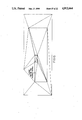
- FIG. 4 is a computer screen display of an object entered by a user from which a mesh of elements for finite element analysis of the object is generated.
- FIG. 5 is a screen display of an initial mesh provided by a rectangular frame generated around the domain of the object.
- FIG. 6 is a screen display of the initial mesh as it appears after a first object point is added to the mesh.
- FIG. 7 is a screen display of the initial mesh as it appears after a second object point has been added to the mesh.
- FIG. 8 is a screen display of the initial mesh after the last object point has been added to the mesh.
- FIG. 9 is a screen display of the mesh illustrating the detection of an element that has failed to meet a predetermined standard of acceptability.
- FIG. 10 is a screen display of the mesh after an expert system rule has been applied to refine the unacceptable element.
- FIG. 11 is a screen display of the mesh illustrating the detection of the second element that has failed to meet the predetermined standard of acceptability.
- FIG. 12 is a screen display of the mesh after another expert system rule has been applied to refine the unacceptable element.
- FIG. 13 is a screen display of the mesh illustrating the detection of a third unacceptable element.
- FIG. 14 is a screen display of the mesh after another expert system rule has been applied to refine the unacceptable element.
- FIG. 15 is a screen display of the mesh illustrating the detection of a fourth unacceptable element.
- FIG. 16 is a screen display of the mesh after another expert system rule has been applied to refine the unacceptable element.
- FIG. 17 is a screen display of the mesh illustrating the detection of a fifth unacceptable element.
- FIG. 18 is a screen display of the mesh after another expert system rule has been applied to refine the unacceptable element.
- FIG. 19 is a screen display of the final mesh after refinement.
- FIG. 20 is a screen display of the initial mesh of an arbitrarily shaped domain that includes a separate subdomain.
- FIG. 21 is a screen display of the final mesh created for the domain of FIG. 20.
- FIG. 22 is a screen display of the final mesh of FIG. 21 with elements outside the domain removed.
- the present invention comprises a method and apparatus for generating a mesh for finite element analysis (FEA) of an object.
- the apparatus and method are embodied within a computer program adapted to run on a workstation manufactured by Apollo Computer, Inc., of Massachusetts or on another computer of comparable power.
- the program is written in the language of C++ from AT&T, although the program could be written in any language suitable for performing the steps to be described herein by one skilled in the art of programming. It should be understood, however, that the apparatus and method of the invention are not necessarily limited to the embodiment of a computer program executable on a computer. The description is given in this context only for the purpose of providing an enabling illustration of the invention.
- the method of the mesh generation according to the present invention is a two-step automatic process that requires no user input once a geometric representation of the object has been provided to the program. Each of the two major process steps comprises a number of internal steps.
- an initial mesh of elements is generated directly in the first step from points the program selects that define the subdomains of the object.
- the mesh elements in the present embodiment are triangular in shape, although quadrilaterals or other polygons that are comprised of triangles could be created as an intermediate step if so desired.
- This initial mesh is not usually satisfactory for finite element analysis. Many of the elements generated will likely have shapes that are unacceptable for analysis because of poor aspect ratios. That is, the ratio of the largest side or angle of the polygon to the smallest side or angle is too great. Elements with poor aspect ratios produce an ill-conditioned matrix that introduces error into the approximation of the characteristic due to the mesh.
- the second step of the process comprises the use of a rule-based expert system that applies a set of rules to refine each unacceptable element in the initial mesh.
- the method refines each element that fails to meet a predetermined standard of acceptability, such as an aspect ratio of no greater than 3:1 for each element.
- a predetermined standard of acceptability such as an aspect ratio of no greater than 3:1 for each element.
- it is first determined which rule of the set "fires" to refine the element's shape.
- the appropriate rule is then applied.
- the above steps are repeated until each element is no longer refined by the application of a rule. This condition is met when all elements meet the predetermined standard or can no longer be refined.
- the object geometry Prior to performing the meshing method, the object geometry is entered into a data base associated with the program.
- the means of entry may take the form of a conventional computer-aided design (CAD) or equivalent drafting program that allows the user to enter a geometric representation of the object into the data base by simply drawing the object on the computer screen.
- geometric data representing the object may be entered as a data file or directly by the user via a keyboard.
- a collection of points defining the object and specified by coordinates is provided in a conventional manner before the method begins.
- This definition of the object for generating the mesh is not necessarily limited to geometric data. Data on other physical characteristics of interest such as the object's thermal conductivities, material strength, etc., could also form the basis for mesh generation.
- a data base associated with the present method would thus have stored therein a list of components and their thermal properties.
- Means are provided in the program for defining the object in terms of points selected from the point collection within the data base.
- the points that are selected define each subdomain of the object.
- a subdomain is a separate geometric region of the object, such as a hole through the object, a component mounted on a circuit board or a rod pivotally attached to a piston.
- the endpoints are selected.
- the curve section such as a conic section, the curve is first approximated by polyline segments before selecting the endpoints of each of the segments.
- the endpoint that defines the beginning and end of each subdomain outline is then marked specifically for later recall. That marked point will be considered twice in generating elements in the initial mesh.
- FIG. 4 the screen display of an irregularly shaped object 40 such as a printed circuit board is shown entered into the computer memory for finite element analysis.
- This particular object has as its subdomains only the domain itself. To simplify the example without taking from its value, no components that would create other subdomains are included.
- the object 40 there are eight separate endpoints of line segments, with the first endpoint defining the beginning (1) and the end (9) of the subdomain outline. The order of points is determined by the user in his manner of entering the geometric data representation of the object, such as by drawing it. Where no order is user-determined, the program defaults to a predetermined order.
- FIGS. 1-3 of the drawings there are shown three flowcharts that illustrate the method and apparatus of the invention.
- FIG. 1 illustrates the overall method, with the first step being the guilding or generating the initial mesh of elements.
- the internal steps generating the mesh are illustrated in the flowcharts of FIGS. 2 and 3.
- each step described herein will be followed by a numeral that identifies the step on the flowchart.
- the method begins in FIG. 1 by executing that part of the program that builds the initial mesh (150).
- the object (subdomain) points of the object are first retrieved (152).
- these are points 1-9 of object 40 shown in FIG. 4.
- the coordinates of these points are evaluated by the program, and as shown in FIG. 5 an initial bounding rectangular frame defined by four bounding vertices 10-13 is produced around the object 40 (154).
- the frame is spaced a predetermined minimum distance from the object points to form a mesh boundary.
- the greatest x coordinate difference and y coordinate difference are calculated. A percentage of each difference is then added to the respective sides of the object to provide the spacing.
- Opposite endpoints 10 and 11 of the rectangular frame are then connected as a diagonal 41 to form a mesh of two triangular elements 42 and 44.
- Each subdomain point is now considered (156) and added separately within the mesh of elements 42 and 44 (158) to generate the initial mesh.
- the internal steps for generating elements from the addition of the new subdomain point to the existing mesh are shown in FIG. 3.
- the algorithm therein is a unique modification of an algorithm created by B. Delaunay and described by D. T. Lee and B. J. Schachter in "Two Algorithms for Constructing a Delaunay Triangulation," International Journal of Computer Information Science, Vol. 9, No. 3 (1980).
- the modification takes into account the presence of "reserved” edges and thus enables the algorithm to generate an acceptable initial mesh.
- a reserved edge is a line connecting two subdomain pints and, in effect, forming a subdomain boundary.
- the element enclosing this current point is found (160).
- the original diagonal 41 of FIG. 5 is shown as a dashed line, with the subdomain point 1 enclosed within triangular element 44.
- the subdomain point is then connected to each of the element's nodes, points 10, 11, and 12, to construct or create three triangles and up to four convex quadrilaterals that each include a newly constructed triangle with the current subdomain point (162).
- the present example only one convex quadrilateral that has as its vertices points 1, 10, 13, and 11 is created at this stage.
- Each quadrilateral created is then checked individually (164).
- the quadrilateral diagonal that does not pass through th subdomain point is checked to see if it is a reserved edge (166).
- This first diagonal is also an edge of the created triangle that includes the subdomain point. Once a reserved edge is formed in the mesh, it is not changed. Since point 1 is the first object point considered, however, no reserved edge has yet been created.
- the next step (168) computes the circumcircle of the newly created triangle 48 defined by points 1, 10, and 11.
- a circumcircle is a circle whose circumference passes through each vertex of a triangle.
- a portion of the circumcircle 50 for triangular element 48 is shown in FIG. 6.
- Point 13 the fourth point of the quadrilateral, is then checked to determine if it is within the circumcircle (170).
- point 13 lies well within the circumcircle and, consequently, the first quadrilateral diagonal 41 is swapped for the second quadrilateral diagonal 52 (172).
- the swapping of diagonals removes triangular element 48 and creates two new triangular elements that contain the current subdomain point, triangle 54 defined by points 1, 11, and 13 and triangle 56 defined by points 1, 10, and 13.
- the steps 166-172 are then repeated for each new quadrilateral created that contains a newly constructed triangle with the subdomain point 1 until no further diagonal swapping is required (174).
- none of the other existing diagonals are swapped at this stage and the program returns to FIG. 2 (175).
- the program checks to see if it is in a "subdomain" mode (176).
- the subdomain mode is only entered by points following the first point. Initially, therefore, the program is not in its subdomain mode and it proceeds to determine if the current point, point 1, defines the beginning of a subdomain (178). Point 1 is indeed the beginning of the subdomain since it was entered first by the user. Point 1 is then saved as the last point considered and the subdomain mode is entered (180). The point is then checked to determine if it is the subdomain ending. The answer is negative. Point 1 is not the subdomain end, although it has the same coordinates with point 9 (182).
- FIG. 7 illustrates the change in the mesh after the second subdomain point has been added.
- the subdomain point is added (158), and the program branches to the steps of FIG. 3 to find the enclosing element for the point (160).
- the enclosing element is triangle 54, shown in solid lines in FIG. 6 and in dashed lines in FIG. 7.
- Point 2 is then connected with the vertices of the triangle 54 to create three new triangles and two new convex quadrilaterals. For each new convex quadrilateral created (164), the diagonal not passing through point 2 is checked to see if it is a reserved edge.
- FIG. 7 illustrates the change in the mesh after the second subdomain point has been added.
- the program branches to the steps of FIG. 3 to find the enclosing element for the point (160).
- the enclosing element is triangle 54, shown in solid lines in FIG. 6 and in dashed lines in FIG. 7.
- Point 2 is then connected with the vertices of the triangle 54
- the program now enters the subdomain mode (176) and the program checks to determine if there is now a connection in the mesh between the current point, point 2, and the last point, point 1 (186). In FIG. 7 there is such a connection and it is marked as a reserved edge 64 (188). Point 2 is then saved as the last point (192) as well as being the current point. Proceeding through the rest of the loop, point 2 is determined by the program not to be the subdomain beginning (178) or subdomain ending (182).
- step 156 of FIG. 2 The program continues to loop back to step 156 of FIG. 2 until each of the subdomain points is placed within the mesh and the resulting mesh elements generated.
- FIG. 8 shows the completion of the initial mesh after the ninth, ending point has been considered.
- point 9 is determined to be the subdomain ending and the program exits the subdomain mode (184). If another subdomain were present, such as a component mounted on the object 40, the program would loop back to step 156 and continue again. Once all subdomain points in the entire domain have been added, the program exits the loop (194) and returns to FIG. 1 to proceed with the next step.
- no connection is made between the current subdomain point added and the previous, last point (186).
- another line may cross between two points on a subdomain boundary such as between points 7 and 8.
- the program generates additional points on the subdomain boundary in an attempt to change the mesh and build the reserved edge (195).
- a new point is added at a location on the subdomain boundary between the two object points such that no element edge crosses the subdomain boundary between the new point and the previous point (196).
- the program branches (158) to the meshing algorithm of FIG. 3. This will build a reserved edge between this new point and the last point. More importantly the new point will have changed the mesh and possibly removed the original crossing element edge.
- This process through step 186, 195, and 196 continues with new points continually added until the reserved edge between the current and previous point is complete.
- each element is analyzed to determine if it meets a predetermined standard of acceptability and, if not, it is automatically refined.
- the process of refinement adds additional points according to a rule-based expert system. The additional points increase the number of elements and change the appearance of the mesh.
- the second step begins with assigning FALSE to a Boolean variable Fixed -- One (197) and the initialization to the start of a list of the elements generated by the program. Each element in the mesh is then checked individually (198).
- the program determines if the element meets the standard of acceptability (200).
- This standard can take many forms but typically is a desired aspect ratio or minimum element angle such as 25° in the present embodiment. It should be noted that the greater the minimum angle required, the more time-consuming the mesh generation. Twenty-five degrees, it is believed, provides an acceptable mesh for analysis purposes while still allowing extremely fast mesh generation. Moreover, angle determination is preferred over length of edge determination because the angle calculation can be made much faster. Whatever standard is chosen, an element that meets it is considered acceptable for finite element analysis.
- the triangle has three edges either reserved and/or on the mesh boundary:
- the triangle has two edges either reserved and/or on the mesh boundary:
- the triangle's longest edge is either reserved and/or on the mesh boundary:
- the triangle has an edge either reserved and/or on the mesh boundary:
- Rule 1 is a trivial rule that covers the rare case of an element which has all its edges reserved. In Rule 3, the 3/8 distance specified is preferred, but the rule will work within a range of between 1/4 and 1/2 of the way from the minimum angle vertex.
- Rules 8 and 9 are "catchall" rules that rarely fire. Both Rules 8 and 9 are intended to influence the area around an element such that either the swapping of the Delaunay triangulation algorithm or the addition of more nodes by these rules will improve the element's shape.
- the algorithm of FIG. 3 is applied each time a node (point) is added.
- the new node may generate other elements that have unacceptable shapes. Eventually, however, all elements created will pass the acceptability standard or be considered no further refinable.
- triangular element 66 that does not pass th standard of acceptability because it minimum angle is less than the minimum specified.
- the rules are then applied to this element (202) in the numerical order given.
- none of the edges of triangle 66 are reserved or are on the mesh boundary
- Rule 4 initially applies because the neighboring element 68 across from the longest edge does not have its longest edge 70 either reserved or on the mesh boundary. But the center (not shown) of the circumcircle containing triangle 66 is outside the mesh boundary, causing Rule 4 to be superseded by Rule 5.
- Rule 5 a new node 72 is placed at the intersection of a line connecting the center of the circumcircle to the triangle centroid and the nearest reserved edge (204).
- FIGS. 11 and 12 show another unacceptable element and the new node added in response by Rule 4.
- FIG. 13 shows a third unacceptable element and FIG. 14 the application of and response by Rule 3.
- FIG. 15 shows a fourth unacceptable element and FIG. 16 the application of and response by Rule 2.
- FIG. 17 shows a fifth unacceptable element and FIG. 18 the application of and response by Rule 6.
- FIG. 19 shows the final refinement of the mesh.
- FIGS. 20-22 show an example of another arbitrarily shaped object for which a mesh is generated.
- the subdomain points herein include points from polyline segments on the curve as well as points of an inner circle defining a separate subdomain.
- FIG. 20 shows the initial mesh;
- FIG. 21 shows the final mesh; and
- FIG. 22 the final mesh with the elements outside the domain removed.
- this method generated a complete mesh for the object 40 in about one second.
- the mesh for the arbitrarily shaped object of FIGS. 20-22 was completed in about four seconds.
- a mesh for a printed circuit board with 25 components took about 13 seconds and for a board with 1,000 components, one and a half minutes.
- Prior art methods would have taken from hours to days.
Landscapes
- Engineering & Computer Science (AREA)
- Physics & Mathematics (AREA)
- Theoretical Computer Science (AREA)
- Geometry (AREA)
- General Physics & Mathematics (AREA)
- Software Systems (AREA)
- Computer Graphics (AREA)
- Computer Hardware Design (AREA)
- Evolutionary Computation (AREA)
- General Engineering & Computer Science (AREA)
- Processing Or Creating Images (AREA)
- Image Generation (AREA)
- Management, Administration, Business Operations System, And Electronic Commerce (AREA)
Priority Applications (5)
| Application Number | Priority Date | Filing Date | Title |
|---|---|---|---|
| US07/151,105 US4912664A (en) | 1988-02-01 | 1988-02-01 | Method and apparatus for generating a mesh for finite element analysis |
| EP19890902579 EP0402372A4 (en) | 1988-02-01 | 1989-01-27 | Generating a mesh for finite element analysis |
| JP1502392A JPH03502381A (ja) | 1988-02-01 | 1989-01-27 | 有限エレメント解析のためのメッシュ生成方法及び装置 |
| PCT/US1989/000357 WO1989007301A1 (fr) | 1988-02-01 | 1989-01-27 | Generation de grille d'analyse d'elements finis |
| CA000589798A CA1301352C (fr) | 1988-02-01 | 1989-02-01 | Appareil generant une grille d'analyse par la methode des elements finis et methode connexe |
Applications Claiming Priority (1)
| Application Number | Priority Date | Filing Date | Title |
|---|---|---|---|
| US07/151,105 US4912664A (en) | 1988-02-01 | 1988-02-01 | Method and apparatus for generating a mesh for finite element analysis |
Publications (1)
| Publication Number | Publication Date |
|---|---|
| US4912664A true US4912664A (en) | 1990-03-27 |
Family
ID=22537334
Family Applications (1)
| Application Number | Title | Priority Date | Filing Date |
|---|---|---|---|
| US07/151,105 Expired - Lifetime US4912664A (en) | 1988-02-01 | 1988-02-01 | Method and apparatus for generating a mesh for finite element analysis |
Country Status (5)
| Country | Link |
|---|---|
| US (1) | US4912664A (fr) |
| EP (1) | EP0402372A4 (fr) |
| JP (1) | JPH03502381A (fr) |
| CA (1) | CA1301352C (fr) |
| WO (1) | WO1989007301A1 (fr) |
Cited By (73)
| Publication number | Priority date | Publication date | Assignee | Title |
|---|---|---|---|---|
| WO1991001529A1 (fr) * | 1989-07-10 | 1991-02-07 | General Electric Company | Augmentation spatiale de sommets adoucissant la transition des details |
| EP0478257A2 (fr) * | 1990-09-24 | 1992-04-01 | International Business Machines Corporation | Méthode et appareil pour la production d'image tridimensionelle |
| US5125038A (en) * | 1991-01-22 | 1992-06-23 | International Business Machine Corporation | Face and edge trim method for an automatic mesh generation system |
| US5193145A (en) * | 1990-02-16 | 1993-03-09 | Silicon Graphics, Inc. | Method and apparatus for producing a visually improved image in a computer system |
| US5214752A (en) * | 1991-01-22 | 1993-05-25 | International Business Machines Corporation | Point placement method for use in a three-dimensional automatic mesh generation system |
| US5282140A (en) * | 1992-06-24 | 1994-01-25 | Intel Corporation | Particle flux shadowing for three-dimensional topography simulation |
| US5307292A (en) * | 1992-06-24 | 1994-04-26 | Christopher A. Brown | Method of quantifying the topographic structure of a surface |
| US5315537A (en) * | 1991-04-08 | 1994-05-24 | Blacker Teddy D | Automated quadrilateral surface discretization method and apparatus usable to generate mesh in a finite element analysis system |
| US5333248A (en) * | 1992-07-15 | 1994-07-26 | International Business Machines Corporation | Method and system for the smooth contouring of triangulated surfaces |
| US5367615A (en) * | 1989-07-10 | 1994-11-22 | General Electric Company | Spatial augmentation of vertices and continuous level of detail transition for smoothly varying terrain polygon density |
| US5367465A (en) * | 1992-06-24 | 1994-11-22 | Intel Corporation | Solids surface grid generation for three-dimensional topography simulation |
| US5377118A (en) * | 1992-06-24 | 1994-12-27 | Intel Corporation | Method for accurate calculation of vertex movement for three-dimensional topography simulation |
| US5379225A (en) * | 1992-06-24 | 1995-01-03 | Intel Corporation | Method for efficient calculation of vertex movement for three-dimensional topography simulation |
| US5398307A (en) * | 1990-07-06 | 1995-03-14 | Matsushita Electric Industrial Co., Ltd. | Mesh generating method and apparatus therefor |
| US5408598A (en) * | 1991-05-23 | 1995-04-18 | International Business Machines Corporation | Method for fast generation of parametric curves employing a pre-calculated number of line segments in accordance with a determined error threshold |
| US5416729A (en) * | 1992-06-24 | 1995-05-16 | Nippon Telegraph And Telephone Corporation | Generalized solids modeling for three-dimensional topography simulation |
| US5428726A (en) * | 1992-08-28 | 1995-06-27 | University Of South Florida | Triangulation of random and scattered data |
| US5440674A (en) * | 1991-07-31 | 1995-08-08 | Park; Joon Y. | Mesh generation with quasi-equilateral triangulation for finite element analyses |
| US5442569A (en) * | 1993-06-23 | 1995-08-15 | Oceanautes Inc. | Method and apparatus for system characterization and analysis using finite element methods |
| US5453934A (en) * | 1993-03-26 | 1995-09-26 | Cray Research, Inc. | Method for use in designing an arbitrarily shaped object |
| US5553009A (en) * | 1993-09-10 | 1996-09-03 | International Business Machines Corporation | Parallel method for subdivision of arbitrary curved solids |
| US5555356A (en) * | 1992-10-29 | 1996-09-10 | International Business Machines Corporation | System and method for generating a trimmed parametric surface for display on a graphic display device |
| US5561748A (en) * | 1990-11-26 | 1996-10-01 | International Business Machines Corporation | Method and apparatus for creating solid models from two-dimensional drawings on a graphics display |
| US5586230A (en) * | 1992-06-24 | 1996-12-17 | Intel Corporation | Surface sweeping method for surface movement in three dimensional topography simulation |
| US5590248A (en) * | 1992-01-02 | 1996-12-31 | General Electric Company | Method for reducing the complexity of a polygonal mesh |
| US5602979A (en) * | 1993-08-27 | 1997-02-11 | Apple Computer, Inc. | System and method for generating smooth low degree polynomial spline surfaces over irregular meshes |
| US5617322A (en) * | 1994-01-31 | 1997-04-01 | Nec Corporation | Mesh generator and generating method |
| US5644688A (en) * | 1992-06-24 | 1997-07-01 | Leon; Francisco A. | Boolean trajectory solid surface movement method |
| US5649079A (en) * | 1994-02-28 | 1997-07-15 | Holmes; David I. | Computerized method using isosceles triangles for generating surface points |
| US5654771A (en) * | 1995-05-23 | 1997-08-05 | The University Of Rochester | Video compression system using a dense motion vector field and a triangular patch mesh overlay model |
| US5664064A (en) * | 1994-01-27 | 1997-09-02 | Hitachi Engineering Co., Ltd. | Object form division method and system |
| US5671395A (en) * | 1993-09-17 | 1997-09-23 | Nec Corporation | Method and system for dividing analyzing region in device simulator |
| US5675521A (en) * | 1994-02-11 | 1997-10-07 | The United States Of America As Represented By The Secretary Of The Air Force | Multichip module analyzer |
| US5675522A (en) * | 1993-09-17 | 1997-10-07 | Nec Corporation | Method and system for dividing analyzing region in device simulator |
| US5760779A (en) * | 1994-06-29 | 1998-06-02 | Hitachi, Ltd. | Method and apparatus for generating an analyzing mesh for a three-dimensional area |
| US5768156A (en) * | 1995-10-25 | 1998-06-16 | Sandia Corporation | Connectivity-based, all-hexahedral mesh generation method and apparatus |
| US5774696A (en) * | 1995-05-29 | 1998-06-30 | Nec Corporation | Triangle and tetrahedron mesh generation method |
| US5838594A (en) * | 1995-02-24 | 1998-11-17 | Fujitsu Limited | Method and apparatus for generating finite element meshes, and analyzing method and apparatus |
| US5850229A (en) * | 1995-12-15 | 1998-12-15 | Raindrop Geomagic, Inc. | Apparatus and method for geometric morphing |
| US5880977A (en) * | 1996-03-28 | 1999-03-09 | Nec Corporation | Mesh generation device and its method for generating meshes having a boundary protective layer |
| US5886702A (en) * | 1996-10-16 | 1999-03-23 | Real-Time Geometry Corporation | System and method for computer modeling of 3D objects or surfaces by mesh constructions having optimal quality characteristics and dynamic resolution capabilities |
| WO1999018517A2 (fr) * | 1997-10-08 | 1999-04-15 | Rivara Maria Cecilia | Systeme de raffinement et de deraffinement sur la base du bord le plus long et procede de production automatique de reseau maille |
| US5905657A (en) * | 1996-12-19 | 1999-05-18 | Schlumberger Technology Corporation | Performing geoscience interpretation with simulated data |
| US5936869A (en) * | 1995-05-25 | 1999-08-10 | Matsushita Electric Industrial Co., Ltd. | Method and device for generating mesh for use in numerical analysis |
| US5946479A (en) * | 1995-05-25 | 1999-08-31 | Matsushita Electric Industrial Co., Ltd. | Method and device for generating mesh for use in numerical analysis |
| US5945996A (en) * | 1996-10-16 | 1999-08-31 | Real-Time Geometry Corporation | System and method for rapidly generating an optimal mesh model of a 3D object or surface |
| US6002406A (en) * | 1996-11-13 | 1999-12-14 | Silicon Graphics, Inc. | System and method for storing and accessing data representative of an object in various level-of-detail |
| US6011914A (en) * | 1996-09-20 | 2000-01-04 | Nec Corporation | Method for simulating diffusion of impurity materials in semiconductor devices |
| US6052650A (en) * | 1997-02-27 | 2000-04-18 | Schlumberger Technology Corporation | Enforcing consistency in geoscience models |
| US6115046A (en) * | 1990-11-26 | 2000-09-05 | International Business Machines Corporation | Method and apparatus for generating three dimensional drawing on a graphics display |
| US6128577A (en) * | 1996-12-19 | 2000-10-03 | Schlumberger Technology Corporation | Modeling geological structures and properties |
| US6208347B1 (en) | 1997-06-23 | 2001-03-27 | Real-Time Geometry Corporation | System and method for computer modeling of 3D objects and 2D images by mesh constructions that incorporate non-spatial data such as color or texture |
| US6249600B1 (en) * | 1997-11-07 | 2001-06-19 | The Trustees Of Columbia University In The City Of New York | System and method for generation of a three-dimensional solid model |
| US6313837B1 (en) | 1998-09-29 | 2001-11-06 | Schlumberger Technology Corporation | Modeling at more than one level of resolution |
| US6348921B1 (en) | 1996-04-12 | 2002-02-19 | Ze Hong Zhao | System and method for displaying different portions of an object in different levels of detail |
| US6356263B2 (en) | 1999-01-27 | 2002-03-12 | Viewpoint Corporation | Adaptive subdivision of mesh models |
| US6389582B1 (en) | 1995-12-21 | 2002-05-14 | John Valainis | Thermal driven placement |
| US6407743B1 (en) | 1998-10-20 | 2002-06-18 | Microsoft Corporation | System and method for morphing based on multiple weighted parameters |
| US6505326B1 (en) * | 2000-09-29 | 2003-01-07 | General Electric Company | Analyzing thermal characteristics of geometries |
| US6504541B1 (en) * | 1998-10-21 | 2003-01-07 | Tele Atlas North America, Inc. | Warping geometric objects |
| US6526550B1 (en) * | 2000-09-29 | 2003-02-25 | General Electric Company | Analyzing characteristics of geometries |
| US6542157B1 (en) * | 1997-11-07 | 2003-04-01 | Canon Kabushiki Kaisha | Font decoration by automatic mesh fitting |
| KR100406828B1 (en) * | 2003-05-21 | 2003-11-22 | Shape Co Ltd | Finite element analysis method of rotary forming process |
| US6693646B1 (en) * | 1999-04-28 | 2004-02-17 | Microsoft Corporation | Method and system for iterative morphing |
| US20040044507A1 (en) * | 2002-08-30 | 2004-03-04 | Fujitsu Limited | Mesh creating device, mesh creating method and mesh creating program |
| US20040054509A1 (en) * | 2002-09-12 | 2004-03-18 | Breit Stephen R. | System and method for preparing a solid model for meshing |
| US20040073401A1 (en) * | 2002-10-15 | 2004-04-15 | General Electric Company | Method for positioning defects in metal billets, and related articles |
| US6993463B1 (en) * | 2001-01-18 | 2006-01-31 | Sandia Corporation | Method for die design and powder pressing |
| US20070120851A1 (en) * | 2005-11-29 | 2007-05-31 | Siemens Corporate Research Inc | Method and Apparatus for Fast and Efficient Mesh Simplification |
| US20120136636A1 (en) * | 2010-11-26 | 2012-05-31 | Adrian Kleine | Finite element adjustment for basin faults |
| US20120200569A1 (en) * | 2011-02-07 | 2012-08-09 | Munkberg Carl J | Micropolygon Splatting |
| US8601428B2 (en) | 2011-12-13 | 2013-12-03 | Qualcomm Incorporated | System and method for use case-based thermal analysis of heuristically determined component combinations and layouts in a portable computing device |
| US8949094B2 (en) | 2012-04-02 | 2015-02-03 | Honda Motor Co., Ltd. | Thermal deflection analysis |
Families Citing this family (5)
| Publication number | Priority date | Publication date | Assignee | Title |
|---|---|---|---|---|
| CA2062911A1 (fr) * | 1991-05-17 | 1992-11-18 | Stephen C. Gates | Systeme infographique et methode d'auto-pavage d'objets graphiques |
| US6037949A (en) * | 1997-08-04 | 2000-03-14 | Pixar Animation Studios | Texture mapping and other uses of scalar fields on subdivision surfaces in computer graphics and animation |
| US6300960B1 (en) | 1997-08-04 | 2001-10-09 | Pixar Animation Studios | Realistic surface simulation in computer animation |
| US6222553B1 (en) | 1997-08-04 | 2001-04-24 | Pixar Animation Studios | Hybrid subdivision in computer graphics |
| EP1711904A4 (fr) * | 2003-12-19 | 2010-02-10 | Esi Group | Procedes de generation de representations numeriques ou visuelles d'une geometrie de surface tesselee fermee |
Citations (12)
| Publication number | Priority date | Publication date | Assignee | Title |
|---|---|---|---|---|
| US4628532A (en) * | 1983-07-14 | 1986-12-09 | Scan Optics, Inc. | Alphanumeric handprint recognition |
| US4646251A (en) * | 1985-10-03 | 1987-02-24 | Evans & Sutherland Computer Corporation | Computer graphics, parametric patch parallel subdivision processor |
| US4649498A (en) * | 1984-05-08 | 1987-03-10 | The University Of Rochester | Computer systems for curve-solid classification and solid modeling |
| US4700402A (en) * | 1982-09-14 | 1987-10-13 | Dainippon Screen Seizo Kabushiki Kaisha | Input method for graphic pattern data |
| US4736306A (en) * | 1985-04-29 | 1988-04-05 | The United States Of America As Represented By The United States Department Of Energy | System for conversion between the boundary representation model and a constructive solid geometry model of an object |
| US4742473A (en) * | 1985-07-16 | 1988-05-03 | Shugar Joel K | Finite element modeling system |
| US4748675A (en) * | 1984-11-09 | 1988-05-31 | Hitachi, Ltd. | Method for controlling image processing device |
| US4766556A (en) * | 1984-11-20 | 1988-08-23 | Matsushita Electric Industrial Co., Ltd. | Three-dimensional solid object manipulating apparatus and method therefor |
| US4771474A (en) * | 1983-10-03 | 1988-09-13 | Shaken Co., Ltd. | Apparatus for processing character or pictorial image data |
| US4775946A (en) * | 1985-03-29 | 1988-10-04 | Hitachi, Ltd. | Method for constructing three-dimensional polyhedron model |
| US4791583A (en) * | 1987-05-04 | 1988-12-13 | Caterpillar Inc. | Method for global blending of computer modeled solid objects using a convolution integral |
| US4797842A (en) * | 1985-03-28 | 1989-01-10 | International Business Machines Corporation | Method of generating finite elements using the symmetric axis transform |
-
1988
- 1988-02-01 US US07/151,105 patent/US4912664A/en not_active Expired - Lifetime
-
1989
- 1989-01-27 JP JP1502392A patent/JPH03502381A/ja active Pending
- 1989-01-27 WO PCT/US1989/000357 patent/WO1989007301A1/fr not_active Application Discontinuation
- 1989-01-27 EP EP19890902579 patent/EP0402372A4/en not_active Withdrawn
- 1989-02-01 CA CA000589798A patent/CA1301352C/fr not_active Expired - Fee Related
Patent Citations (12)
| Publication number | Priority date | Publication date | Assignee | Title |
|---|---|---|---|---|
| US4700402A (en) * | 1982-09-14 | 1987-10-13 | Dainippon Screen Seizo Kabushiki Kaisha | Input method for graphic pattern data |
| US4628532A (en) * | 1983-07-14 | 1986-12-09 | Scan Optics, Inc. | Alphanumeric handprint recognition |
| US4771474A (en) * | 1983-10-03 | 1988-09-13 | Shaken Co., Ltd. | Apparatus for processing character or pictorial image data |
| US4649498A (en) * | 1984-05-08 | 1987-03-10 | The University Of Rochester | Computer systems for curve-solid classification and solid modeling |
| US4748675A (en) * | 1984-11-09 | 1988-05-31 | Hitachi, Ltd. | Method for controlling image processing device |
| US4766556A (en) * | 1984-11-20 | 1988-08-23 | Matsushita Electric Industrial Co., Ltd. | Three-dimensional solid object manipulating apparatus and method therefor |
| US4797842A (en) * | 1985-03-28 | 1989-01-10 | International Business Machines Corporation | Method of generating finite elements using the symmetric axis transform |
| US4775946A (en) * | 1985-03-29 | 1988-10-04 | Hitachi, Ltd. | Method for constructing three-dimensional polyhedron model |
| US4736306A (en) * | 1985-04-29 | 1988-04-05 | The United States Of America As Represented By The United States Department Of Energy | System for conversion between the boundary representation model and a constructive solid geometry model of an object |
| US4742473A (en) * | 1985-07-16 | 1988-05-03 | Shugar Joel K | Finite element modeling system |
| US4646251A (en) * | 1985-10-03 | 1987-02-24 | Evans & Sutherland Computer Corporation | Computer graphics, parametric patch parallel subdivision processor |
| US4791583A (en) * | 1987-05-04 | 1988-12-13 | Caterpillar Inc. | Method for global blending of computer modeled solid objects using a convolution integral |
Non-Patent Citations (12)
| Title |
|---|
| "Lou Crain: The Man Behind Patran," CAE (Jul. 1987). |
| "PCs Ease the Use of FEA," CAE (Jul. 1987). |
| Klein, "How to Design with Finite-Element Analysis," Plastics Design Forum (Sep. Oct. 1987). |
| Klein, How to Design with Finite Element Analysis, Plastics Design Forum (Sep. Oct. 1987). * |
| LaBonte et al., "Keep pc boards reliable with thermal-analysis tools", Electronic Design (Apr. 28, 1988). |
| LaBonte et al., Keep pc boards reliable with thermal analysis tools , Electronic Design (Apr. 28, 1988). * |
| Lou Crain: The Man Behind Patran, CAE (Jul. 1987). * |
| PCs Ease the Use of FEA, CAE (Jul. 1987). * |
| Rouse, "Fighting it Out in Finite Elements," Machine Design (Apr. 9, 1987). |
| Rouse, Fighting it Out in Finite Elements, Machine Design (Apr. 9, 1987). * |
| Schiermeier et al., "An Alternate Algorithm for FEA," Computers in Mechanical Engineering (Jan. 1987). |
| Schiermeier et al., An Alternate Algorithm for FEA, Computers in Mechanical Engineering (Jan. 1987). * |
Cited By (87)
| Publication number | Priority date | Publication date | Assignee | Title |
|---|---|---|---|---|
| US5367615A (en) * | 1989-07-10 | 1994-11-22 | General Electric Company | Spatial augmentation of vertices and continuous level of detail transition for smoothly varying terrain polygon density |
| WO1991001529A1 (fr) * | 1989-07-10 | 1991-02-07 | General Electric Company | Augmentation spatiale de sommets adoucissant la transition des details |
| US5193145A (en) * | 1990-02-16 | 1993-03-09 | Silicon Graphics, Inc. | Method and apparatus for producing a visually improved image in a computer system |
| US5398307A (en) * | 1990-07-06 | 1995-03-14 | Matsushita Electric Industrial Co., Ltd. | Mesh generating method and apparatus therefor |
| EP0478257A3 (en) * | 1990-09-24 | 1994-05-11 | Ibm | Method and apparatus for producing three dimensional image |
| EP0478257A2 (fr) * | 1990-09-24 | 1992-04-01 | International Business Machines Corporation | Méthode et appareil pour la production d'image tridimensionelle |
| US5561748A (en) * | 1990-11-26 | 1996-10-01 | International Business Machines Corporation | Method and apparatus for creating solid models from two-dimensional drawings on a graphics display |
| US6115046A (en) * | 1990-11-26 | 2000-09-05 | International Business Machines Corporation | Method and apparatus for generating three dimensional drawing on a graphics display |
| US5214752A (en) * | 1991-01-22 | 1993-05-25 | International Business Machines Corporation | Point placement method for use in a three-dimensional automatic mesh generation system |
| US5125038A (en) * | 1991-01-22 | 1992-06-23 | International Business Machine Corporation | Face and edge trim method for an automatic mesh generation system |
| US5315537A (en) * | 1991-04-08 | 1994-05-24 | Blacker Teddy D | Automated quadrilateral surface discretization method and apparatus usable to generate mesh in a finite element analysis system |
| US5408598A (en) * | 1991-05-23 | 1995-04-18 | International Business Machines Corporation | Method for fast generation of parametric curves employing a pre-calculated number of line segments in accordance with a determined error threshold |
| US5440674A (en) * | 1991-07-31 | 1995-08-08 | Park; Joon Y. | Mesh generation with quasi-equilateral triangulation for finite element analyses |
| US5590248A (en) * | 1992-01-02 | 1996-12-31 | General Electric Company | Method for reducing the complexity of a polygonal mesh |
| US5307292A (en) * | 1992-06-24 | 1994-04-26 | Christopher A. Brown | Method of quantifying the topographic structure of a surface |
| US5379225A (en) * | 1992-06-24 | 1995-01-03 | Intel Corporation | Method for efficient calculation of vertex movement for three-dimensional topography simulation |
| US5416729A (en) * | 1992-06-24 | 1995-05-16 | Nippon Telegraph And Telephone Corporation | Generalized solids modeling for three-dimensional topography simulation |
| US5377118A (en) * | 1992-06-24 | 1994-12-27 | Intel Corporation | Method for accurate calculation of vertex movement for three-dimensional topography simulation |
| US5367465A (en) * | 1992-06-24 | 1994-11-22 | Intel Corporation | Solids surface grid generation for three-dimensional topography simulation |
| US5586230A (en) * | 1992-06-24 | 1996-12-17 | Intel Corporation | Surface sweeping method for surface movement in three dimensional topography simulation |
| US5644688A (en) * | 1992-06-24 | 1997-07-01 | Leon; Francisco A. | Boolean trajectory solid surface movement method |
| US5282140A (en) * | 1992-06-24 | 1994-01-25 | Intel Corporation | Particle flux shadowing for three-dimensional topography simulation |
| US5333248A (en) * | 1992-07-15 | 1994-07-26 | International Business Machines Corporation | Method and system for the smooth contouring of triangulated surfaces |
| US5428726A (en) * | 1992-08-28 | 1995-06-27 | University Of South Florida | Triangulation of random and scattered data |
| US5555356A (en) * | 1992-10-29 | 1996-09-10 | International Business Machines Corporation | System and method for generating a trimmed parametric surface for display on a graphic display device |
| US5453934A (en) * | 1993-03-26 | 1995-09-26 | Cray Research, Inc. | Method for use in designing an arbitrarily shaped object |
| US5442569A (en) * | 1993-06-23 | 1995-08-15 | Oceanautes Inc. | Method and apparatus for system characterization and analysis using finite element methods |
| US5602979A (en) * | 1993-08-27 | 1997-02-11 | Apple Computer, Inc. | System and method for generating smooth low degree polynomial spline surfaces over irregular meshes |
| US5553009A (en) * | 1993-09-10 | 1996-09-03 | International Business Machines Corporation | Parallel method for subdivision of arbitrary curved solids |
| US5671395A (en) * | 1993-09-17 | 1997-09-23 | Nec Corporation | Method and system for dividing analyzing region in device simulator |
| US5675522A (en) * | 1993-09-17 | 1997-10-07 | Nec Corporation | Method and system for dividing analyzing region in device simulator |
| US5664064A (en) * | 1994-01-27 | 1997-09-02 | Hitachi Engineering Co., Ltd. | Object form division method and system |
| US5617322A (en) * | 1994-01-31 | 1997-04-01 | Nec Corporation | Mesh generator and generating method |
| US5675521A (en) * | 1994-02-11 | 1997-10-07 | The United States Of America As Represented By The Secretary Of The Air Force | Multichip module analyzer |
| US5649079A (en) * | 1994-02-28 | 1997-07-15 | Holmes; David I. | Computerized method using isosceles triangles for generating surface points |
| US5760779A (en) * | 1994-06-29 | 1998-06-02 | Hitachi, Ltd. | Method and apparatus for generating an analyzing mesh for a three-dimensional area |
| US5838594A (en) * | 1995-02-24 | 1998-11-17 | Fujitsu Limited | Method and apparatus for generating finite element meshes, and analyzing method and apparatus |
| US5654771A (en) * | 1995-05-23 | 1997-08-05 | The University Of Rochester | Video compression system using a dense motion vector field and a triangular patch mesh overlay model |
| US5946479A (en) * | 1995-05-25 | 1999-08-31 | Matsushita Electric Industrial Co., Ltd. | Method and device for generating mesh for use in numerical analysis |
| US5936869A (en) * | 1995-05-25 | 1999-08-10 | Matsushita Electric Industrial Co., Ltd. | Method and device for generating mesh for use in numerical analysis |
| US5774696A (en) * | 1995-05-29 | 1998-06-30 | Nec Corporation | Triangle and tetrahedron mesh generation method |
| US5768156A (en) * | 1995-10-25 | 1998-06-16 | Sandia Corporation | Connectivity-based, all-hexahedral mesh generation method and apparatus |
| US5850229A (en) * | 1995-12-15 | 1998-12-15 | Raindrop Geomagic, Inc. | Apparatus and method for geometric morphing |
| US6389582B1 (en) | 1995-12-21 | 2002-05-14 | John Valainis | Thermal driven placement |
| US5880977A (en) * | 1996-03-28 | 1999-03-09 | Nec Corporation | Mesh generation device and its method for generating meshes having a boundary protective layer |
| US6348921B1 (en) | 1996-04-12 | 2002-02-19 | Ze Hong Zhao | System and method for displaying different portions of an object in different levels of detail |
| US6011914A (en) * | 1996-09-20 | 2000-01-04 | Nec Corporation | Method for simulating diffusion of impurity materials in semiconductor devices |
| US6611267B2 (en) | 1996-10-16 | 2003-08-26 | Viewpoint Corporation | System and method for computer modeling of 3D objects or surfaces by mesh constructions having optimal quality characteristics and dynamic resolution capabilities |
| US5945996A (en) * | 1996-10-16 | 1999-08-31 | Real-Time Geometry Corporation | System and method for rapidly generating an optimal mesh model of a 3D object or surface |
| US6392647B1 (en) | 1996-10-16 | 2002-05-21 | Viewpoint Corporation | System and method for computer modeling of 3D objects or surfaces by mesh constructions having optimal quality characteristics and dynamic resolution capabilities |
| US6262739B1 (en) | 1996-10-16 | 2001-07-17 | Real-Time Geometry Corporation | System and method for computer modeling of 3D objects or surfaces by mesh constructions having optimal quality characteristics and dynamic resolution capabilities |
| US5886702A (en) * | 1996-10-16 | 1999-03-23 | Real-Time Geometry Corporation | System and method for computer modeling of 3D objects or surfaces by mesh constructions having optimal quality characteristics and dynamic resolution capabilities |
| US6002406A (en) * | 1996-11-13 | 1999-12-14 | Silicon Graphics, Inc. | System and method for storing and accessing data representative of an object in various level-of-detail |
| US5905657A (en) * | 1996-12-19 | 1999-05-18 | Schlumberger Technology Corporation | Performing geoscience interpretation with simulated data |
| US6256603B1 (en) | 1996-12-19 | 2001-07-03 | Schlumberger Technology Corporation | Performing geoscience interpretation with simulated data |
| US6128577A (en) * | 1996-12-19 | 2000-10-03 | Schlumberger Technology Corporation | Modeling geological structures and properties |
| US6052650A (en) * | 1997-02-27 | 2000-04-18 | Schlumberger Technology Corporation | Enforcing consistency in geoscience models |
| US6208347B1 (en) | 1997-06-23 | 2001-03-27 | Real-Time Geometry Corporation | System and method for computer modeling of 3D objects and 2D images by mesh constructions that incorporate non-spatial data such as color or texture |
| US20040117163A1 (en) * | 1997-10-08 | 2004-06-17 | Rivara Maria Cecilia | Longest-Edge Refinement and Derefinement System and Method for Automatic Mesh Generation |
| WO1999018517A2 (fr) * | 1997-10-08 | 1999-04-15 | Rivara Maria Cecilia | Systeme de raffinement et de deraffinement sur la base du bord le plus long et procede de production automatique de reseau maille |
| AU747230B2 (en) * | 1997-10-08 | 2002-05-09 | Maria-Cecilia Rivara | Longest-edge refinement and derefinement system and method for automatic mesh generation |
| WO1999018517A3 (fr) * | 1997-10-08 | 1999-06-17 | Rivara Maria Cecilia | Systeme de raffinement et de deraffinement sur la base du bord le plus long et procede de production automatique de reseau maille |
| US6542157B1 (en) * | 1997-11-07 | 2003-04-01 | Canon Kabushiki Kaisha | Font decoration by automatic mesh fitting |
| US6249600B1 (en) * | 1997-11-07 | 2001-06-19 | The Trustees Of Columbia University In The City Of New York | System and method for generation of a three-dimensional solid model |
| US6313837B1 (en) | 1998-09-29 | 2001-11-06 | Schlumberger Technology Corporation | Modeling at more than one level of resolution |
| US6407743B1 (en) | 1998-10-20 | 2002-06-18 | Microsoft Corporation | System and method for morphing based on multiple weighted parameters |
| US6504541B1 (en) * | 1998-10-21 | 2003-01-07 | Tele Atlas North America, Inc. | Warping geometric objects |
| US6356263B2 (en) | 1999-01-27 | 2002-03-12 | Viewpoint Corporation | Adaptive subdivision of mesh models |
| US6693646B1 (en) * | 1999-04-28 | 2004-02-17 | Microsoft Corporation | Method and system for iterative morphing |
| US6526550B1 (en) * | 2000-09-29 | 2003-02-25 | General Electric Company | Analyzing characteristics of geometries |
| US6505326B1 (en) * | 2000-09-29 | 2003-01-07 | General Electric Company | Analyzing thermal characteristics of geometries |
| US6993463B1 (en) * | 2001-01-18 | 2006-01-31 | Sandia Corporation | Method for die design and powder pressing |
| US20040044507A1 (en) * | 2002-08-30 | 2004-03-04 | Fujitsu Limited | Mesh creating device, mesh creating method and mesh creating program |
| US20070118342A1 (en) * | 2002-08-30 | 2007-05-24 | Fujitsu Limited | Mesh creating device, mesh creating method and mesh creating program |
| US7197442B2 (en) * | 2002-08-30 | 2007-03-27 | Fujitsu Limited | Mesh creating device, mesh creating method and mesh creating program |
| US20040054509A1 (en) * | 2002-09-12 | 2004-03-18 | Breit Stephen R. | System and method for preparing a solid model for meshing |
| US20040073401A1 (en) * | 2002-10-15 | 2004-04-15 | General Electric Company | Method for positioning defects in metal billets, and related articles |
| US6909988B2 (en) | 2002-10-15 | 2005-06-21 | General Electric Company | Method for positioning defects in metal billets |
| KR100406828B1 (en) * | 2003-05-21 | 2003-11-22 | Shape Co Ltd | Finite element analysis method of rotary forming process |
| US20070120851A1 (en) * | 2005-11-29 | 2007-05-31 | Siemens Corporate Research Inc | Method and Apparatus for Fast and Efficient Mesh Simplification |
| US7876322B2 (en) * | 2005-11-29 | 2011-01-25 | Siemens Corporation | Method and apparatus for fast and efficient mesh simplification |
| US20120136636A1 (en) * | 2010-11-26 | 2012-05-31 | Adrian Kleine | Finite element adjustment for basin faults |
| US20120200569A1 (en) * | 2011-02-07 | 2012-08-09 | Munkberg Carl J | Micropolygon Splatting |
| US9401046B2 (en) * | 2011-02-07 | 2016-07-26 | Intel Corporation | Micropolygon splatting |
| TWI559257B (zh) * | 2011-02-07 | 2016-11-21 | 英特爾公司 | 使用微多邊形鋪接技術的方法、媒體及設備 |
| US8601428B2 (en) | 2011-12-13 | 2013-12-03 | Qualcomm Incorporated | System and method for use case-based thermal analysis of heuristically determined component combinations and layouts in a portable computing device |
| US8949094B2 (en) | 2012-04-02 | 2015-02-03 | Honda Motor Co., Ltd. | Thermal deflection analysis |
Also Published As
| Publication number | Publication date |
|---|---|
| EP0402372A1 (fr) | 1990-12-19 |
| WO1989007301A1 (fr) | 1989-08-10 |
| JPH03502381A (ja) | 1991-05-30 |
| EP0402372A4 (en) | 1992-03-25 |
| CA1301352C (fr) | 1992-05-19 |
Similar Documents
| Publication | Publication Date | Title |
|---|---|---|
| US4912664A (en) | Method and apparatus for generating a mesh for finite element analysis | |
| Horváth et al. | Modeling and problem solving techniques for engineers | |
| US7952575B2 (en) | Computer-implemented process and system for creating a parametric surface | |
| US6639592B1 (en) | Curve network modeling | |
| US4933889A (en) | Method for fine decomposition in finite element mesh generation | |
| US4797842A (en) | Method of generating finite elements using the symmetric axis transform | |
| Schumaker | Triangulations in CAGD | |
| US7893937B2 (en) | Method for creating a parametric surface symmetric with respect to a given symmetry operation | |
| KR101177131B1 (ko) | 국부 정교화를 이용하여 t-스플라인 및 t-nurcc표면을 정의하기 위한 시스템 및 방법 | |
| Shenton et al. | Three-dimensional finite element mesh generation using Delaunay tesselation | |
| US5774124A (en) | Finite element modeling method and computer system for converting a triangular mesh surface to a quadrilateral mesh surface | |
| JPH0362266A (ja) | 計算機援助図面作成方法 | |
| Hel-Or et al. | Relaxed parametric design with probabilistic constraints | |
| JPH04309183A (ja) | 有限要素メッシュ生成方法 | |
| Fong et al. | An implementation of triangular B-spline surfaces over arbitrary triangulations | |
| US20160042106A1 (en) | Generating a cad model from a finite element mesh | |
| US20020085004A1 (en) | Blending method for accomplishing continuity at boundary of two b-spline curves / surfaces for use in a computing apparatus | |
| Morvan et al. | Ivecs, interactively correcting. stl files in a virtual environment | |
| JP2696972B2 (ja) | フアジイ・ルール発生装置および方法,ならびに確認装置および方法 | |
| JPH04280374A (ja) | 曲面生成方法及びその装置 | |
| Li et al. | Real-time rendering of deformable parametric free-form surfaces | |
| JP3138933B2 (ja) | モデリングシステム | |
| Sussner et al. | Interactive examination of surface quality on car bodies | |
| KR100275274B1 (ko) | 메쉬 데이터량 감축방법 | |
| JP3289230B2 (ja) | 有限要素メッシュ粗密分布の生成装置 |
Legal Events
| Date | Code | Title | Description |
|---|---|---|---|
| AS | Assignment |
Owner name: MENTOR GRAPHICS CORPORATION, 8500 S.W. CREEKSIDE P Free format text: ASSIGNMENT OF ASSIGNORS INTEREST.;ASSIGNORS:WEISS, JONATHAN;FORTNER, PATRICK D.;REEL/FRAME:004845/0139 Effective date: 19880201 Owner name: MENTOR GRAPHICS CORPORATION,OREGON Free format text: ASSIGNMENT OF ASSIGNORS INTEREST;ASSIGNORS:WEISS, JONATHAN;FORTNER, PATRICK D.;REEL/FRAME:004845/0139 Effective date: 19880201 |
|
| FEPP | Fee payment procedure |
Free format text: PAYOR NUMBER ASSIGNED (ORIGINAL EVENT CODE: ASPN); ENTITY STATUS OF PATENT OWNER: LARGE ENTITY |
|
| STCF | Information on status: patent grant |
Free format text: PATENTED CASE |
|
| CC | Certificate of correction | ||
| FEPP | Fee payment procedure |
Free format text: PAYER NUMBER DE-ASSIGNED (ORIGINAL EVENT CODE: RMPN); ENTITY STATUS OF PATENT OWNER: LARGE ENTITY Free format text: PAYOR NUMBER ASSIGNED (ORIGINAL EVENT CODE: ASPN); ENTITY STATUS OF PATENT OWNER: LARGE ENTITY |
|
| FPAY | Fee payment |
Year of fee payment: 4 |
|
| FPAY | Fee payment |
Year of fee payment: 8 |
|
| FPAY | Fee payment |
Year of fee payment: 12 |