US4901622A - Armour constructions - Google Patents

Armour constructions Download PDF

Info

Publication number
US4901622A
US4901622A US07/130,273 US13027387A US4901622A US 4901622 A US4901622 A US 4901622A US 13027387 A US13027387 A US 13027387A US 4901622 A US4901622 A US 4901622A
Authority
US
United States
Prior art keywords
projectile
layer
armour layer
armour
construction
Prior art date
Legal status (The legal status is an assumption and is not a legal conclusion. Google has not performed a legal analysis and makes no representation as to the accuracy of the status listed.)
Expired - Fee Related
Application number
US07/130,273
Inventor
Melvyn Perry
Current Assignee (The listed assignees may be inaccurate. Google has not performed a legal analysis and makes no representation or warranty as to the accuracy of the list.)
BAE Systems Global Combat Systems Munitions Ltd
Original Assignee
Royal Ordnance PLC
Priority date (The priority date is an assumption and is not a legal conclusion. Google has not performed a legal analysis and makes no representation as to the accuracy of the date listed.)
Filing date
Publication date
Application filed by Royal Ordnance PLC filed Critical Royal Ordnance PLC
Assigned to ROYAL ORDNANCE PLC. reassignment ROYAL ORDNANCE PLC. ASSIGNMENT OF ASSIGNORS INTEREST. Assignors: PERRY, MELVYN
Application granted granted Critical
Publication of US4901622A publication Critical patent/US4901622A/en
Anticipated expiration legal-status Critical
Expired - Fee Related legal-status Critical Current

Links

Images

Classifications

    • FMECHANICAL ENGINEERING; LIGHTING; HEATING; WEAPONS; BLASTING
    • F41WEAPONS
    • F41HARMOUR; ARMOURED TURRETS; ARMOURED OR ARMED VEHICLES; MEANS OF ATTACK OR DEFENCE, e.g. CAMOUFLAGE, IN GENERAL
    • F41H5/00Armour; Armour plates
    • F41H5/007Reactive armour; Dynamic armour
    • YGENERAL TAGGING OF NEW TECHNOLOGICAL DEVELOPMENTS; GENERAL TAGGING OF CROSS-SECTIONAL TECHNOLOGIES SPANNING OVER SEVERAL SECTIONS OF THE IPC; TECHNICAL SUBJECTS COVERED BY FORMER USPC CROSS-REFERENCE ART COLLECTIONS [XRACs] AND DIGESTS
    • Y10TECHNICAL SUBJECTS COVERED BY FORMER USPC
    • Y10STECHNICAL SUBJECTS COVERED BY FORMER USPC CROSS-REFERENCE ART COLLECTIONS [XRACs] AND DIGESTS
    • Y10S428/00Stock material or miscellaneous articles
    • Y10S428/911Penetration resistant layer

Landscapes

  • Engineering & Computer Science (AREA)
  • General Engineering & Computer Science (AREA)
  • Aiming, Guidance, Guns With A Light Source, Armor, Camouflage, And Targets (AREA)

Abstract

A reactive armour construction comprises a rigidly fixed outer layer and a relatively loosely fixed inner layer mounted on a structure to be protected in such a way that when a projectile penetrates at an oblique angle the outer layer and is incident upon the inner layer, the inner layer is allowed to move laterally relative to the outer layer thereby disrupting the line of attach of the projectile.

Description

The present invention relates to armour constructions.
Reactive armour constructions are those which defend an underlying structure such as an armoured fighting vehicle by producing by a reaction to an incoming projectile an effect which destroys the penetrative nature of the projectile.
Known reactive armours, e.g. as described in European Pat. Specification No. 0161390A1 depend largely on the use of explosive material to provide the reactive effect which enables the projectile to be defeated.
The present invention provides a novel reactive armour construction which does not depend upon the use of explosive material.
According to the present invention a reactive armour construction comprises a rigidly fixed outer layer and a relatively loosely fixed inner layer mounted on a structure to be protected in such a way that when a projectile penetrates at an oblique angle the outer layer and is incident upon the inner layer, the inner layer is allowed to move laterally relative to the outer layer thereby disrupting the line of attack of the projectile.
Preferably, the outer layer is spaced from the inner layer and the inner layer is spaced from the body to be protected.
The construction according to the invention is particularly suitable for defending structures against high kinetic energy projectiles, e.g. incorporating a heavy metal penetrator. Such projectiles are normally fired with a relatively flat trajectory and are likely to be incident on a target along a path almost parallel to the ground. Therefore, the outer and inner layers need to be arranged to be at an oblique angle to this direction of attack.
The construction according to the invention produces its reactive effect by the movement of the inner layer relative to the outer layer. If an attacking projectile penetrates the outer layer and impinges upon the inner layer the component of momentum of the projectile in a direction in which the inner layer is able to move is significant thereby causing the inner layer to move in that direction. The action of the inner and outer layers consequently resembles that of a guillotine. The line of attack of the projectile is confined generally to that of its original penetration of the outer layer by the passage formed through the outer layer. However, the movement of the inner layer produced by the projectile induces motion of the projectile in a direction parallel to the movement of the inner layer, i.e. in a direction oblique to the original line of attack, and this provides a shearing effect upon the projectile causing the projectile to be defeated.
In general, the tendency for the inner layer to move relative to the outer layer is increased as the kinetic energy of the attacking projectile increases. Therefore, the effectiveness of the projectile defeating mechanism will increase with the projectile kinetic energy.
In the construction according to the present invention the outer and inner layers in their simplest form may be homogeneous metallic layers, e.g. of armour steel plate. One or both of these layers may, alternatively, comprise a composite layer incorporating any of the materials known for use in composite engineering structures.
For example in a simple form a composite material may comprise high strength fibres or fabrics embedded within a suitable matrix. Suitable examples of high strength fibres well known in the composites art are those of aramid, polyamide, polyolefin, carbon, boron, glass and metal. Suitable high strength fabrics are well known in the composites art and are generally formed of woven fibres, for example any of the aforementioned fibres or blends or mixtures of them. Composites containing aramid fibres or fabrics are especially preferred.
The matrix in which the fibres or fabrics are preferably embedded may comprise a polymeric material or an inorganic, e.g. metal or ceramic material. Especially preferred is a laminate structure comprising alternate layers of a high strength fabric and a ceramic. The fabric may be bonded to the ceramic by any suitable adhesive as used in the composites art for the bonding of fabrics to ceramics. The laminate may be formed as one or more sandwiches of a fabric between ceramic layers or, preferably, as one or more sandwiches of a ceramic between fabric layers. Where multiple sandwiches are employed individual layers may be common to adjacent sandwiches.
A preferred composite layer comprises a laminate comprising at least one aramid fabric sub-layer and at least one ceramic sub-layer, e.g. alumina, silicon carbide or boron carbide. Such laminates are known per se, e.g. as described in UK Pat. Application Nos. GB 2,156,272A and 2,130,073A. The aramid fabric may be bonded to the ceramic by any suitable known adhesive or bonding agent, which may for example be a cold setting, thermosetting or thermoplastic material, known to be suitable for bonding aramid to ceramic.
For example, known liquid or powder adhesive may be used to bond together the fabric to the ceramic. The bonding may be by "wet-lay-up" or the layers may be in prepreg form with the adhesive activated by heat and/or other means. Contact adhesive or hot melt adhesive may be used. If desired, the adhesive may be of synthetic resin type, for example, polyester or epoxy resins. The adhesive may also be of a rubber material, for example silicone rubber. If desired the superposed layers may be subjected to pressure during bonding.
Composite layers as described may be used in conjunction with one or more metallic, e.g. armour steel, layers to form overall the outer and/or inner layer described above.
Embodiments of the present invention will now be described by way of example with reference to the accompanying drawings, in which:
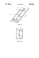
FIG. 1 is a cross-sectional side elevation of an armour construction embodying the present invention;
FIG. 2 is a cross-sectional view on the line II--II shown in FIG. 1 of the construction shown in FIG. 1.
In the construction shown in FIGS. 1 and 2 an outer wall 1 of a body to be protected, e.g. an armoured fighting vehicle, has rigidly fixed thereto an outer armour plate 3. The plate 3 is mounted on the wall 1 by a support shelf 5 and support arms 7 (one only shown in FIG. 1). The plate 3 may be attached to the shelf 5 and arms 7 in any suitable way, e.g. welding, bolting, as will be apparent to those skilled in the art. In the space between the outer plate 3 and the wall 1 is mounted an inner armour layer 9. The layer 9 is supported on rails 11, 13 rigidly attached to the wall 1 and is loosely attached to the shelf 5 and the arms 7 by straps 15 and straps 17 respectively.
When a projectile is incident upon the construction in an approximately horizontal direction labelled P in FIG. 1, i.e. at an acute angle to the outer plate 3, the projectile is likely to penetrate the outer plate and strike the inner plate 3.
Because the inner plate 9 is loosely mounted and is easily moved in an upward direction parallel to the rails 11, 13, as indicated by the arrow labelled M in FIG. 1, and because the attacking projectile has a high component of momentum along the direction M, the projectile causes the straps attached to the plate 9 to be broken and causes the plate 9 to move in the direction M upon impact thereon.
In moving along the direction M the plates 3 and 9 act like a guillotine, as explained above, disrupting the line of penetration of the projectile and thereby breaking up and defeating the projectile. The underlying structure of which the wall 1 is a part is thus protected against the projectile.

Claims (3)

I claim:
1. A reactive armour construction comprising an outer armour layer rigidly fixed by support means to a structure to be protected so that said outer armour layer is spaced from said structure, an inner armour layer disposed in said space between said outer armour layer and said structure, said inner armour layer being supported on rail means rigidly attached to said structure and being relatively loosely attached to said support means by frangible connectors such that when a projectile penetrates at an oblique angle the outer armour layer and is incident upon the inner armour layer, said connectors are broken whereby said inner armour layer is allowed to move laterally upon said rail means relative to said outer armour layer thereby disrupting a line of attack of the projectile.
2. A construction as claimed in claim 1 and wherein the outer and inner layers comprise homogeneous metallic layers.
3. A construction as claimed in claim 1 wherein at least one of the said inner and outer layers comprises a composite layer incorporating a composite material.
US07/130,273 1987-12-08 1987-12-08 Armour constructions Expired - Fee Related US4901622A (en)

Applications Claiming Priority (1)

Application Number Priority Date Filing Date Title
GB8728620A GB2213573B (en) 1987-12-08 1987-12-08 Armour constructions

Publications (1)

Publication Number Publication Date
US4901622A true US4901622A (en) 1990-02-20

Family

ID=10628137

Family Applications (1)

Application Number Title Priority Date Filing Date
US07/130,273 Expired - Fee Related US4901622A (en) 1987-12-08 1987-12-08 Armour constructions

Country Status (2)

Country Link
US (1) US4901622A (en)
GB (1) GB2213573B (en)

Cited By (7)

* Cited by examiner, † Cited by third party
Publication number Priority date Publication date Assignee Title
US5554816A (en) * 1994-05-13 1996-09-10 Skaggs; Samuel R. Reactive ballistic protection devices
US6474213B1 (en) 2000-08-09 2002-11-05 Southwest Research Institute Reactive stiffening armor system
US7163731B2 (en) 1998-03-20 2007-01-16 Rafael Armament Development Authority, Ltd. Lightweight armor against firearm projectiles
US20100011947A1 (en) * 2004-06-03 2010-01-21 Rafael Armament Development Authority Ltd. Passive armor assembly including an armor member made of a brittle material
US7661228B1 (en) * 2005-05-06 2010-02-16 Kontek Industries, Inc. Armored building modules and panels
WO2012039803A1 (en) * 2010-06-22 2012-03-29 Standard Bent Glass Corporation Armor
US9157703B2 (en) 2011-04-01 2015-10-13 Am General Llc Transparent Armor Structure

Families Citing this family (4)

* Cited by examiner, † Cited by third party
Publication number Priority date Publication date Assignee Title
DE4034401A1 (en) * 1990-10-29 1992-04-30 Deutsch Franz Forsch Inst Electromagnetic armour plating - has two metal plates with dielectric and potential difference between them short-circuited by projectile to produce diverting lorentz force
GB0116738D0 (en) 2001-07-09 2001-08-29 Phillips Helmets Ltd Protective headgear and protective armour and a method of modifying protective headgear and protective armour
GB2447233A (en) * 2007-03-06 2008-09-10 Defender Internat Ltd Blast defence barrier
DE102009051301A1 (en) * 2009-10-29 2011-05-05 Rheinmetall Landsysteme Gmbh Protection system especially against multi-projectile projectiles

Citations (14)

* Cited by examiner, † Cited by third party
Publication number Priority date Publication date Assignee Title
DE292799C (en) *
US985640A (en) * 1909-03-02 1911-02-28 William John Stewart Reinforced concrete structure.
US2036903A (en) * 1934-03-05 1936-04-07 Norton Co Cutting-off abrasive wheel
DE631540C (en) * 1933-03-18 1936-06-23 Rudolf Dworaczek Armor using armor plates attached to leather plates
US2190490A (en) * 1937-04-22 1940-02-13 American Rolling Mill Co Structural material
DE697878C (en) * 1937-10-12 1940-10-25 Guenther Muthmann Protective plate against bullet penetration made by folding metal plates
FR866796A (en) * 1940-05-09 1941-09-03 Transparent shield
US2405908A (en) * 1944-04-18 1946-08-13 Saco Lowell Shops Beam driving mechanism for slashers
FR1151196A (en) * 1956-06-05 1958-01-24 & De Construction Soc Et New application of an aluminum alloy for bullet protection and resulting product
DE1127759B (en) * 1959-12-08 1962-04-12 Stromeyer & Co G M B H L Flexible armor against projectile and fragmentation effects
DE1708495A1 (en) * 1966-07-22 1970-01-15 Schoeninger Werkstaetten Ohg Bulletproof switch with rotating payment plate
CA859453A (en) * 1969-08-27 1970-12-29 The Bank Of Nova Scotia Bank teller's worktable
DE2109517A1 (en) * 1971-03-01 1972-09-28 P. Schulte-Stemmerk KG für Industrie und Handel, 4100 Duisburg Expansion joint cover and seal between parallel structures
US3977294A (en) * 1971-09-07 1976-08-31 Fiber Materials, Inc. Composite armor and method

Patent Citations (14)

* Cited by examiner, † Cited by third party
Publication number Priority date Publication date Assignee Title
DE292799C (en) *
US985640A (en) * 1909-03-02 1911-02-28 William John Stewart Reinforced concrete structure.
DE631540C (en) * 1933-03-18 1936-06-23 Rudolf Dworaczek Armor using armor plates attached to leather plates
US2036903A (en) * 1934-03-05 1936-04-07 Norton Co Cutting-off abrasive wheel
US2190490A (en) * 1937-04-22 1940-02-13 American Rolling Mill Co Structural material
DE697878C (en) * 1937-10-12 1940-10-25 Guenther Muthmann Protective plate against bullet penetration made by folding metal plates
FR866796A (en) * 1940-05-09 1941-09-03 Transparent shield
US2405908A (en) * 1944-04-18 1946-08-13 Saco Lowell Shops Beam driving mechanism for slashers
FR1151196A (en) * 1956-06-05 1958-01-24 & De Construction Soc Et New application of an aluminum alloy for bullet protection and resulting product
DE1127759B (en) * 1959-12-08 1962-04-12 Stromeyer & Co G M B H L Flexible armor against projectile and fragmentation effects
DE1708495A1 (en) * 1966-07-22 1970-01-15 Schoeninger Werkstaetten Ohg Bulletproof switch with rotating payment plate
CA859453A (en) * 1969-08-27 1970-12-29 The Bank Of Nova Scotia Bank teller's worktable
DE2109517A1 (en) * 1971-03-01 1972-09-28 P. Schulte-Stemmerk KG für Industrie und Handel, 4100 Duisburg Expansion joint cover and seal between parallel structures
US3977294A (en) * 1971-09-07 1976-08-31 Fiber Materials, Inc. Composite armor and method

Cited By (7)

* Cited by examiner, † Cited by third party
Publication number Priority date Publication date Assignee Title
US5554816A (en) * 1994-05-13 1996-09-10 Skaggs; Samuel R. Reactive ballistic protection devices
US7163731B2 (en) 1998-03-20 2007-01-16 Rafael Armament Development Authority, Ltd. Lightweight armor against firearm projectiles
US6474213B1 (en) 2000-08-09 2002-11-05 Southwest Research Institute Reactive stiffening armor system
US20100011947A1 (en) * 2004-06-03 2010-01-21 Rafael Armament Development Authority Ltd. Passive armor assembly including an armor member made of a brittle material
US7661228B1 (en) * 2005-05-06 2010-02-16 Kontek Industries, Inc. Armored building modules and panels
WO2012039803A1 (en) * 2010-06-22 2012-03-29 Standard Bent Glass Corporation Armor
US9157703B2 (en) 2011-04-01 2015-10-13 Am General Llc Transparent Armor Structure

Also Published As

Publication number Publication date
GB2213573A (en) 1989-08-16
GB8728620D0 (en) 1988-07-13
GB2213573B (en) 1991-02-20

Similar Documents

Publication Publication Date Title
US4131053A (en) Armor plate
US4868040A (en) Antiballistic composite armor
US7866248B2 (en) Encapsulated ceramic composite armor
EP1409948B1 (en) Ceramic armour systems with a front spall layer and a shock absorbing layer
US7562612B2 (en) Ceramic components, ceramic component systems, and ceramic armour systems
US3320619A (en) Lightweight ballistic helmet
US6510777B2 (en) Encapsulated imbricated armor system
US7921759B2 (en) Apparatus for providing protection from ballistic rounds projectiles, fragments and explosives
US6135006A (en) Fiber reinforced ceramic matrix composite armor
US20120017754A1 (en) Armor system and method for defeating high energy projectiles that include metal jets
EP0678724A1 (en) Impact absorbing armor
US8857311B2 (en) Apparatus for providing protection from ballistic rounds, projectiles, fragments and explosives
US4901622A (en) Armour constructions
US8074553B1 (en) Apparatus for providing protection from ballistic rounds, projectiles, fragments and explosives
IL183789A (en) Methods and apparatus for providing ballistic protection
EP2076730B1 (en) Dynamic armor
JPH05502291A (en) Cut resistant composite armor
KR20170081870A (en) Lightweight Armor
CN110375583B (en) Buffering type bulletproof method and bulletproof composite board
WO2008097375A2 (en) Encapsulated ceramic composite armor
CA2500619C (en) Improved ceramic components, ceramic component systems, and ceramic armour systems
RU2390718C1 (en) Armoted element for armor vest protecting against thermally-hardened-core bullets

Legal Events

Date Code Title Description
AS Assignment

Owner name: ROYAL ORDNANCE PLC., ENGLAND

Free format text: ASSIGNMENT OF ASSIGNORS INTEREST.;ASSIGNOR:PERRY, MELVYN;REEL/FRAME:005012/0901

Effective date: 19880328

FEPP Fee payment procedure

Free format text: PAYOR NUMBER ASSIGNED (ORIGINAL EVENT CODE: ASPN); ENTITY STATUS OF PATENT OWNER: LARGE ENTITY

FPAY Fee payment

Year of fee payment: 4

FPAY Fee payment

Year of fee payment: 8

REMI Maintenance fee reminder mailed
LAPS Lapse for failure to pay maintenance fees
STCH Information on status: patent discontinuation

Free format text: PATENT EXPIRED DUE TO NONPAYMENT OF MAINTENANCE FEES UNDER 37 CFR 1.362

FP Lapsed due to failure to pay maintenance fee

Effective date: 20020220