US7163731B2 - Lightweight armor against firearm projectiles - Google Patents
Lightweight armor against firearm projectiles Download PDFInfo
- Publication number
- US7163731B2 US7163731B2 US09/904,585 US90458501A US7163731B2 US 7163731 B2 US7163731 B2 US 7163731B2 US 90458501 A US90458501 A US 90458501A US 7163731 B2 US7163731 B2 US 7163731B2
- Authority
- US
- United States
- Prior art keywords
- armor
- armor assembly
- assembly according
- projectile
- layer
- Prior art date
- Legal status (The legal status is an assumption and is not a legal conclusion. Google has not performed a legal analysis and makes no representation as to the accuracy of the status listed.)
- Expired - Fee Related
Links
Images


Classifications
-
- F—MECHANICAL ENGINEERING; LIGHTING; HEATING; WEAPONS; BLASTING
- F41—WEAPONS
- F41H—ARMOUR; ARMOURED TURRETS; ARMOURED OR ARMED VEHICLES; MEANS OF ATTACK OR DEFENCE, e.g. CAMOUFLAGE, IN GENERAL
- F41H5/00—Armour; Armour plates
- F41H5/02—Plate construction
- F41H5/04—Plate construction composed of more than one layer
- F41H5/0407—Transparent bullet-proof laminatesinformative reference: layered products essentially comprising glass in general B32B17/06, e.g. B32B17/10009; manufacture or composition of glass, e.g. joining glass to glass C03; permanent multiple-glazing windows, e.g. with spacing therebetween, E06B3/66
-
- F—MECHANICAL ENGINEERING; LIGHTING; HEATING; WEAPONS; BLASTING
- F41—WEAPONS
- F41H—ARMOUR; ARMOURED TURRETS; ARMOURED OR ARMED VEHICLES; MEANS OF ATTACK OR DEFENCE, e.g. CAMOUFLAGE, IN GENERAL
- F41H5/00—Armour; Armour plates
- F41H5/02—Plate construction
- F41H5/04—Plate construction composed of more than one layer
-
- Y—GENERAL TAGGING OF NEW TECHNOLOGICAL DEVELOPMENTS; GENERAL TAGGING OF CROSS-SECTIONAL TECHNOLOGIES SPANNING OVER SEVERAL SECTIONS OF THE IPC; TECHNICAL SUBJECTS COVERED BY FORMER USPC CROSS-REFERENCE ART COLLECTIONS [XRACs] AND DIGESTS
- Y10—TECHNICAL SUBJECTS COVERED BY FORMER USPC
- Y10S—TECHNICAL SUBJECTS COVERED BY FORMER USPC CROSS-REFERENCE ART COLLECTIONS [XRACs] AND DIGESTS
- Y10S428/00—Stock material or miscellaneous articles
- Y10S428/911—Penetration resistant layer
-
- Y—GENERAL TAGGING OF NEW TECHNOLOGICAL DEVELOPMENTS; GENERAL TAGGING OF CROSS-SECTIONAL TECHNOLOGIES SPANNING OVER SEVERAL SECTIONS OF THE IPC; TECHNICAL SUBJECTS COVERED BY FORMER USPC CROSS-REFERENCE ART COLLECTIONS [XRACs] AND DIGESTS
- Y10—TECHNICAL SUBJECTS COVERED BY FORMER USPC
- Y10T—TECHNICAL SUBJECTS COVERED BY FORMER US CLASSIFICATION
- Y10T428/00—Stock material or miscellaneous articles
- Y10T428/24—Structurally defined web or sheet [e.g., overall dimension, etc.]
- Y10T428/24058—Structurally defined web or sheet [e.g., overall dimension, etc.] including grain, strips, or filamentary elements in respective layers or components in angular relation
- Y10T428/24074—Strand or strand-portions
- Y10T428/24116—Oblique to direction of web
-
- Y—GENERAL TAGGING OF NEW TECHNOLOGICAL DEVELOPMENTS; GENERAL TAGGING OF CROSS-SECTIONAL TECHNOLOGIES SPANNING OVER SEVERAL SECTIONS OF THE IPC; TECHNICAL SUBJECTS COVERED BY FORMER USPC CROSS-REFERENCE ART COLLECTIONS [XRACs] AND DIGESTS
- Y10—TECHNICAL SUBJECTS COVERED BY FORMER USPC
- Y10T—TECHNICAL SUBJECTS COVERED BY FORMER US CLASSIFICATION
- Y10T428/00—Stock material or miscellaneous articles
- Y10T428/24—Structurally defined web or sheet [e.g., overall dimension, etc.]
- Y10T428/24174—Structurally defined web or sheet [e.g., overall dimension, etc.] including sheet or component perpendicular to plane of web or sheet
-
- Y—GENERAL TAGGING OF NEW TECHNOLOGICAL DEVELOPMENTS; GENERAL TAGGING OF CROSS-SECTIONAL TECHNOLOGIES SPANNING OVER SEVERAL SECTIONS OF THE IPC; TECHNICAL SUBJECTS COVERED BY FORMER USPC CROSS-REFERENCE ART COLLECTIONS [XRACs] AND DIGESTS
- Y10—TECHNICAL SUBJECTS COVERED BY FORMER USPC
- Y10T—TECHNICAL SUBJECTS COVERED BY FORMER US CLASSIFICATION
- Y10T428/00—Stock material or miscellaneous articles
- Y10T428/24—Structurally defined web or sheet [e.g., overall dimension, etc.]
- Y10T428/24752—Laterally noncoextensive components
- Y10T428/2476—Fabric, cloth or textile component
-
- Y—GENERAL TAGGING OF NEW TECHNOLOGICAL DEVELOPMENTS; GENERAL TAGGING OF CROSS-SECTIONAL TECHNOLOGIES SPANNING OVER SEVERAL SECTIONS OF THE IPC; TECHNICAL SUBJECTS COVERED BY FORMER USPC CROSS-REFERENCE ART COLLECTIONS [XRACs] AND DIGESTS
- Y10—TECHNICAL SUBJECTS COVERED BY FORMER USPC
- Y10T—TECHNICAL SUBJECTS COVERED BY FORMER US CLASSIFICATION
- Y10T442/00—Fabric [woven, knitted, or nonwoven textile or cloth, etc.]
- Y10T442/20—Coated or impregnated woven, knit, or nonwoven fabric which is not [a] associated with another preformed layer or fiber layer or, [b] with respect to woven and knit, characterized, respectively, by a particular or differential weave or knit, wherein the coating or impregnation is neither a foamed material nor a free metal or alloy layer
Definitions
- the present invention is in the field of armor against regular and armor piercing firearm projectiles and their fragments as well as debris of various objects (collectively referred to herein the specification and claims as projectiles), and aims at providing an armor suitable for a variety of purposes such as for making protective garments, for fitting enclosures with armored wall portions and the like.
- laminated glass panels e.g. 11 to 40 mm thick or even more, which by the effect of their mechanical properties are resistant against the penetration of various types of firearms.
- the thickness has to be increased, thereby reducing the visibility of such armor panels.
- such panels are very heavy, weighing about 3 to 4 times more than an opaque armor, and also costly and therefore impractical for many purposes. There is thus an ever increasing need for armor material, in particular lightweight and transparent armor shields.
- prior art armor shields are aimed at providing an armor which deforms the shape of the projectile or of its fragments, thus decreasing its penetration ability by reducing its kinetic energy
- the invention is based on the surprising observation that an armor made of at least one panel of brittle, low fracture toughness material, facing the expected path of a firearm projectile and slantingly oriented with respect to the path of a firearm projectile, subjects the projectile to forces which cause it to be diverted from its original trajectory by virtue of impact forces acting on the projectile as it penetrates through the armor.
- Additional layers of material may be introduced behind the brittle material, thus imparting the armor further resistance and durability and to increase protection of an object extending behind the armor.
- the arrangement is such that the projectile is diverted in direction essentially perpendicular to the panel of brittle material, and where the armor comprises one or more layers made of ductile material behind the panel of brittle material, the projectile and fragments of the brittle material will not reach the protected object.
- the one or more ductile layers may adjoin the layer of brittle material or may extent at a different angle with respect thereto.
- the armor comprises a front layer made of an essentially brittle material and a rear layer made of ductile material, adjoining the front layer and constituting a backing layer.
- the rear layer i.e. the backup layer may be made of metal, typically steel or aluminum, or of a polymer e.g. PU (Polyurethane), PVC (polyvinylchloride), where transparency is required.
- the front layer is made of a woven or other pliable material, whereby the projectile is diverted by virtue of asymmetric impact forces.
- the armor comprises a plurality of armor layers arranged in a serrated layout, the armor layers being essentially parallel to one another and extending tilted with respect to an expected trajectory of a projectile.
- the material of the front and rear layers used in accordance with the present invention may be transparent or opaque. However, it is in many cases advantageous that it is made of a transparent material, whereby one can see through it.
- materials suitable for use as the front layer are glass, glass ceramics, PerspexTM, Plexi Glass, PMMA (poly methyl metha acrylate), ALON, Sapphir, Spinelle, various synthetic materials, epoxy resins etc.—all being transparent, brittle materials. It may be monoblock, laminated or composite, e.g. a glass body sheathed between PerspexTM plates. Transparent PerspexTM plates may be covered with scratch-resistant materials e.g. glass or other suitable coatings.
- the rear layer is also transparent.
- the obtuse angle is the upper one, the impinging firearm projectile is deflected upwards. In contrast, where the obtuse angle is the lower one an impinging firearm projectile is deflected downward.
- An opaque front pliable material may, for example, be made of a heavy duty cloth material such as of KevlarTM, SpectraTM, and various epoxy materials. Such materials may be used as they are in composite form, e.g. by being impregnated with a suitable different polymeric material which hardens upon curing.
- a plurality of slanting front layers may be formed together into a multi-layer block in which adjacent layers are suitably glued or cemented to each other. In cases of a thick front layer the projectile may be deflected without penetration.
- an oncoming firearm projectile penetrates the at least one front layer and when it emerges therefrom, either intact or broken up, it is deflected from its trajectory, and does not penetrate the protected object. In some cases the projectile will not penetrate through the front layer, made of a brittle, low fracture toughness material.
- FIG. 1 is a schematic illustration showing the manner in which the invention operates in case of armor made of a single slanted layer made of a brittle material;
- FIG. 2 is a schematic enlargement of a portion of the armor according to FIG. 1 , illustrating forces acting during penetration of a projectile through the armor;
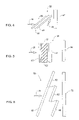
- FIG. 3 is an illustration for two successive slanted armor layers, both made of a low fracture toughness material
- FIG. 4 is a schematic illustration of an embodiment according to the present invention, with the armor being a composite body comprising several layers;
- FIG. 5 is a schematic illustration of still another embodiment of the invention.
- FIG. 6 is a schematic representation of an armor according to the invention illustrating a serrated structure suitable for protecting a large object.
- FIG. 1 there is shown schematically an armor assembly comprising a slanted armor panel 1 extending in front of a body 2 which is to be protected by the armor panel 1 .
- An oncoming firearm projectile 3 is depicted in form of an arrow and as can easily be concluded from the figure, the trajectory of projectile 3 is essentially normal to the body 2 , whilst the armor panel 1 extends at a slant with respect to the trajectory of projectile 3 .
- the armor panel 1 is made of an essentially brittle, low fracture toughness material, such as, for example, glass, glass ceramics, PerspexTM, Plexi Glass, PMMA (Poly Metal Meta Acrilate), ALON, Sapphir, Spinelle, various synthetic materials, epoxy resins, etc.
- the armor panel 1 may be transparent or opaque, depending on the intended use of the armor assembly.
- the panel 1 may be monoblock, laminate or composite, e.g. a glass body sheathed between PerspexTM plates or Transparent PerspexTM plates, which may be covered with scratch-resistant materials e.g. glass or other suitable coatings.
- the arrangement in accordance with this embodiment is such that as the projectile penetrates through the armor panel 1 it is imparted side impact which cause it to deflect from its original trajectory and maintain its deflection as it emerges from the armor panel 1 in direction of arrow 4 . It is appreciated that in some cases the projectile will not even penetrate through the front body.
- the obtuse angle is the upper one.
- the projectile 3 once the projectile 3 has penetrated across panel 1 it is diverted upwards as shown by arrow 4 , either as a whole or broken up, and either does not at all hit the body 2 , or else is readily intercepted by it without passing across.
- An advantage of the armor assembly according to the present invention is that it is essentially lightweight such that it is suitable for use as a personal armor garment, etc.
- the armor is transparent, rendering it suitable for use as a protection armor for protecting windows and domes of vehicles and crafts, etc.
- the arrangement according to this embodiment is such that owing to impact forces the projectile is imparted asymmetric impact forces as it penetrates through the panel, whereby it is diverted from its original trajectory i.e. essentially normal to the plane of the panel, as resembled by the arrow 4 .
- FIG. 2 which is an enlargement of the portion designated II in FIG. 1 , there is illustrated a portion 28 of the armor panel designated 18 , which gives rise to generating the impact forces acting on the projectile 20 , thus imparting it a component force in direction of arrow 30 diverting it in the direction of arrow 26 , preventing it from reaching protected body 24 , or significantly reducing its kinetic energy.
- FIG. 3 In the embodiment shown schematically in FIG. 3 , in which similar components are marked by similar numerals, there are provided two differently slanted panels 1 and 5 .
- the oncoming firearm projectile 3 is deflected by panel 1 in the manner shown at 6 at which it may still be in a position to penetrate across the second (rear) panel 5 where it is again deflected into the direction shown by arrow 7 , the end result being similar as in FIG. 1 but with a larger deflection of the projectile from its original trajectory.
- the rear layer may be made of a metal e.g. steel or aluminum, or of a polymer e.g. PU (Polyurethane), PVC (polyvinylchloride), where transparency is required.
- PU Polyurethane
- PVC polyvinylchloride
- panel 35 is inclined with respect to the expected trajectory of a projectile, and comprises several layers.
- a middle layer 36 made of a brittle material and is sheathed by a front layer 38 made for example of a pliable material e.g. heavy duty cloth material such as of KevlarTM, SpectraTM and a rear layer 40 of a low toughens fracture material.
- Layers 38 and 40 are suitable for protecting the panel 36 and preventing shrapnel and debris of the panel 36 from striking object 47 .
- This embodiment operates in a combined way namely, the projectile 42 is imparted asymmetric impact forces as it penetrates through the layer 36 and then the projectile emerges from layer 40 as indicated by arrow 46 , diverted from its original trajectory path preventing it from hitting the protected body 47 .
- FIG. 5 discloses an armor panel generally designated 50 and comprising a front layer 52 and a block 54 composed of a plurality of slanting plates 56 glued or cemented together.
- a rear layer of ductile material 58 extends as a backing behind the panel/block 54 and in front of the body to be protected 59 .
- the firearm projectile 60 is diverted by any of the plates 56 which it hits on its way, and it accordingly does not penetrate the rear layer 58 .
- FIG. 6 represents a protective armor generally designated 70 for protecting an object 72 . It is readily understood that in order for the armor to extend in front of object 72 and inclined with respect to the trajectory of an expected threat 78 , it would have to extend as illustrated by the dashed line portion 80 and would consume a significantly large space. Accordingly, the armor consists of a plurality of parallelly extending sections 82 , consuming less space.
Abstract
An armor assembly for protecting a body disposed behind said armor assembly, wherein the armor assembly comprises at least one layer of material made of an essentially brittle material, said layer extending slanted relative the expected trajectory of an oncoming firearm projectile.
Description
The present application is a continuation-in-part of Ser. No. 09/263,845, filed Mar. 8, 1999, now abandoned.
The present invention is in the field of armor against regular and armor piercing firearm projectiles and their fragments as well as debris of various objects (collectively referred to herein the specification and claims as projectiles), and aims at providing an armor suitable for a variety of purposes such as for making protective garments, for fitting enclosures with armored wall portions and the like.
There is a widespread need for protected enclosures with firearm projectile resistant wall portions, transparent or not. Typical examples where transparent such armor is required are shop windows in riot prone areas, armored car windows, fighter plane domes, helicopter windows, domes for a tank commander post, etc.
According to the prior art it is customary to use for such purposes laminated glass panels, e.g. 11 to 40 mm thick or even more, which by the effect of their mechanical properties are resistant against the penetration of various types of firearms. Where it is required to increase the penetration resistance of the armor, the thickness has to be increased, thereby reducing the visibility of such armor panels. Furthermore, such panels are very heavy, weighing about 3 to 4 times more than an opaque armor, and also costly and therefore impractical for many purposes. There is thus an ever increasing need for armor material, in particular lightweight and transparent armor shields.
There is also a widespread need for firearm projectile resistant pliable material, e.g. for making protective garments, bullet resistant tarpaulins and the like. There is furthermore a need for lightweight opaque armor against firearms.
Whilst prior art armor shields are aimed at providing an armor which deforms the shape of the projectile or of its fragments, thus decreasing its penetration ability by reducing its kinetic energy, it is an object of the present invention to provide an armor which diverts the trajectory of the projectile or the fragments thereof. This object is carried out whilst carrying out the above needs.
It is the general object of the present invention to provide an armor which diverts the trajectory of the projectile striking said armor. This object is achieved by imparting the projectile with deflecting momentum as it penetrates through the armor, whereby the trajectory of the projectile is diverted from its original course.
The invention is based on the surprising observation that an armor made of at least one panel of brittle, low fracture toughness material, facing the expected path of a firearm projectile and slantingly oriented with respect to the path of a firearm projectile, subjects the projectile to forces which cause it to be diverted from its original trajectory by virtue of impact forces acting on the projectile as it penetrates through the armor.
Additional layers of material may be introduced behind the brittle material, thus imparting the armor further resistance and durability and to increase protection of an object extending behind the armor.
The arrangement is such that the projectile is diverted in direction essentially perpendicular to the panel of brittle material, and where the armor comprises one or more layers made of ductile material behind the panel of brittle material, the projectile and fragments of the brittle material will not reach the protected object. The one or more ductile layers may adjoin the layer of brittle material or may extent at a different angle with respect thereto.
According to one specific embodiment of the invention, the armor comprises a front layer made of an essentially brittle material and a rear layer made of ductile material, adjoining the front layer and constituting a backing layer. The rear layer i.e. the backup layer may be made of metal, typically steel or aluminum, or of a polymer e.g. PU (Polyurethane), PVC (polyvinylchloride), where transparency is required.
By one particular embodiment, the front layer is made of a woven or other pliable material, whereby the projectile is diverted by virtue of asymmetric impact forces.
According to the present invention the armor comprises a plurality of armor layers arranged in a serrated layout, the armor layers being essentially parallel to one another and extending tilted with respect to an expected trajectory of a projectile.
The material of the front and rear layers used in accordance with the present invention may be transparent or opaque. However, it is in many cases advantageous that it is made of a transparent material, whereby one can see through it. Examples of materials suitable for use as the front layer are glass, glass ceramics, Perspex™, Plexi Glass, PMMA (poly methyl metha acrylate), ALON, Sapphir, Spinelle, various synthetic materials, epoxy resins etc.—all being transparent, brittle materials. It may be monoblock, laminated or composite, e.g. a glass body sheathed between Perspex™ plates. Transparent Perspex™ plates may be covered with scratch-resistant materials e.g. glass or other suitable coatings.
In case of a transparent front layer, it is desired that the rear layer is also transparent.
Where out of the two complementary angles formed between the trajectory of the firearm projectile and the surface of said at least one front layer the obtuse angle is the upper one, the impinging firearm projectile is deflected upwards. In contrast, where the obtuse angle is the lower one an impinging firearm projectile is deflected downward.
An opaque front pliable material may, for example, be made of a heavy duty cloth material such as of Kevlar™, Spectra™, and various epoxy materials. Such materials may be used as they are in composite form, e.g. by being impregnated with a suitable different polymeric material which hardens upon curing.
If desired, a plurality of slanting front layers may be formed together into a multi-layer block in which adjacent layers are suitably glued or cemented to each other. In cases of a thick front layer the projectile may be deflected without penetration.
In operation an oncoming firearm projectile penetrates the at least one front layer and when it emerges therefrom, either intact or broken up, it is deflected from its trajectory, and does not penetrate the protected object. In some cases the projectile will not penetrate through the front layer, made of a brittle, low fracture toughness material.
For better understanding the invention and to see how it may be carried out in practice, some embodiments will now be described, in a non-limiting manner, with reference to the accompanying drawings, in which:
Turning first to FIG. 1 , there is shown schematically an armor assembly comprising a slanted armor panel 1 extending in front of a body 2 which is to be protected by the armor panel 1. An oncoming firearm projectile 3 is depicted in form of an arrow and as can easily be concluded from the figure, the trajectory of projectile 3 is essentially normal to the body 2, whilst the armor panel 1 extends at a slant with respect to the trajectory of projectile 3.
In the embodiment of FIG. 1 the armor panel 1 is made of an essentially brittle, low fracture toughness material, such as, for example, glass, glass ceramics, Perspex™, Plexi Glass, PMMA (Poly Metal Meta Acrilate), ALON, Sapphir, Spinelle, various synthetic materials, epoxy resins, etc. The armor panel 1 may be transparent or opaque, depending on the intended use of the armor assembly. Furthermore, the panel 1 may be monoblock, laminate or composite, e.g. a glass body sheathed between Perspex™ plates or Transparent Perspex™ plates, which may be covered with scratch-resistant materials e.g. glass or other suitable coatings.
The arrangement in accordance with this embodiment is such that as the projectile penetrates through the armor panel 1 it is imparted side impact which cause it to deflect from its original trajectory and maintain its deflection as it emerges from the armor panel 1 in direction of arrow 4. It is appreciated that in some cases the projectile will not even penetrate through the front body.
As can further be seen, of the two angles formed at the intersection of the trajectory of projectile 3 with armor panel 1, the obtuse angle is the upper one. In consequence, once the projectile 3 has penetrated across panel 1 it is diverted upwards as shown by arrow 4, either as a whole or broken up, and either does not at all hit the body 2, or else is readily intercepted by it without passing across.
An advantage of the armor assembly according to the present invention is that it is essentially lightweight such that it is suitable for use as a personal armor garment, etc. According to some particular embodiments the armor is transparent, rendering it suitable for use as a protection armor for protecting windows and domes of vehicles and crafts, etc.
The arrangement according to this embodiment is such that owing to impact forces the projectile is imparted asymmetric impact forces as it penetrates through the panel, whereby it is diverted from its original trajectory i.e. essentially normal to the plane of the panel, as resembled by the arrow 4.
In FIG. 2 , which is an enlargement of the portion designated II in FIG. 1 , there is illustrated a portion 28 of the armor panel designated 18, which gives rise to generating the impact forces acting on the projectile 20, thus imparting it a component force in direction of arrow 30 diverting it in the direction of arrow 26, preventing it from reaching protected body 24, or significantly reducing its kinetic energy.
In the embodiment shown schematically in FIG. 3 , in which similar components are marked by similar numerals, there are provided two differently slanted panels 1 and 5. In this arrangement the oncoming firearm projectile 3 is deflected by panel 1 in the manner shown at 6 at which it may still be in a position to penetrate across the second (rear) panel 5 where it is again deflected into the direction shown by arrow 7, the end result being similar as in FIG. 1 but with a larger deflection of the projectile from its original trajectory. The rear layer may be made of a metal e.g. steel or aluminum, or of a polymer e.g. PU (Polyurethane), PVC (polyvinylchloride), where transparency is required.
In the embodiment of the invention schematically shown in FIG. 4 , panel 35 is inclined with respect to the expected trajectory of a projectile, and comprises several layers. A middle layer 36 made of a brittle material and is sheathed by a front layer 38 made for example of a pliable material e.g. heavy duty cloth material such as of Kevlar™, Spectra™ and a rear layer 40 of a low toughens fracture material. Layers 38 and 40 are suitable for protecting the panel 36 and preventing shrapnel and debris of the panel 36 from striking object 47. This embodiment operates in a combined way namely, the projectile 42 is imparted asymmetric impact forces as it penetrates through the layer 36 and then the projectile emerges from layer 40 as indicated by arrow 46, diverted from its original trajectory path preventing it from hitting the protected body 47.
The embodiment shown schematically in FIG. 5 discloses an armor panel generally designated 50 and comprising a front layer 52 and a block 54 composed of a plurality of slanting plates 56 glued or cemented together. A rear layer of ductile material 58 extends as a backing behind the panel/block 54 and in front of the body to be protected 59. In its passage across block 54 the firearm projectile 60 is diverted by any of the plates 56 which it hits on its way, and it accordingly does not penetrate the rear layer 58.
The schematic illustration of FIG. 6 represents a protective armor generally designated 70 for protecting an object 72. It is readily understood that in order for the armor to extend in front of object 72 and inclined with respect to the trajectory of an expected threat 78, it would have to extend as illustrated by the dashed line portion 80 and would consume a significantly large space. Accordingly, the armor consists of a plurality of parallelly extending sections 82, consuming less space.
Claims (20)
1. An armor assembly for protecting a body disposed behind said armor assembly from oncoming regular and armor piercing firearm projectiles striking said armor assembly, wherein the armor assembly comprises a front panel including at least one armor layer made of a light-weight brittle material selected from the group consisting of poly methyl methacrylate (PMMA) and epoxy resin, said armor layer being slantingly oriented relative to the expected trajectory of the oncoming projectile and being slantingly oriented to the body being protected, and said armor layer constituting means for deflecting the projectile from its original course.
2. An armor assembly according to claim 1 , wherein said front panel includes a plurality of layers, at least one of which is made of a material selected from the group consisting of poly methyl methacrylate (PMMA) and epoxy resin.
3. An armor assembly according to claim 2 , wherein said armor layer is covered with a layer of brittle material.
4. An armor assembly according to claim 3 , wherein said brittle material is glass.
5. An armor assembly according to claim 1 , comprising a plurality of armor layers made of PMMA or epoxy resin and arranged in a serrated layout, the armor layers being essentially parallel to one another and slantingly oriented with respect to the expected trajectory of the oncoming firearm projectile.
6. An armor assembly according to claim 1 , comprising a rear panel situated behind the front panel.
7. An armor assembly according to claim 6 , wherein the rear panel is made of a ductile material.
8. An armor assembly according to claim 7 , wherein said ductile material is pliable.
9. An armor assembly according to claim 6 wherein said rear panel adjoins the front panel.
10. An armor assembly according to claim 9 wherein said rear panel constitutes backing for the front panel.
11. An armor material according to claim 1 , wherein said armor layer is made of a transparent material.
12. An armor assembly according to claim 1 , wherein said armor layer is opaque.
13. An armor assembly according to claim 1 , wherein said front panel is made of a monoblock.
14. An armor assembly according to claim 1 , wherein said front panel is made of a composite material.
15. An armor assembly according to claim 1 , wherein said front panel is made of a plurality of different lightweight transparent materials.
16. An armor assembly according to claim 1 , wherein the front panel consists of a plurality of individual sublayers, wherein the individual sublayers are slantingly oriented with respect to the expected trajectory of the oncoming firearm projectile.
17. An armor assembly according to claim 1 , wherein said armor layer is such that the firearm projectile penetrates it, and when it emerges therefrom, either intact or broken up, it is deflected from its trajectory.
18. An armor assembly according to claim 1 , wherein the armor layer is thick, such that the projectile is deflected without penetration.
19. An armor assembly for protecting a body disposed behind said armor assembly from oncoming regular and armor piercing firearm projectiles striking said armor assembly, wherein the armor assembly comprises a front panel composed of a plurality of plates, said plates being made of a light-weight brittle material selected from the group consisting of poly methyl methacrylate (PMMA) and epoxy resin and slanting in respect of the expected trajectory of said oncoming projectile, so as to divert said projectile when impacting said plates, and said plates being slantingly oriented to the body being protected.
20. An armor assembly for protecting a body disposed behind said armor assembly from oncoming regular and armor piercing firearm projectiles striking said armor assembly, wherein the armor assembly comprises a front panel having a front surface and including at least one armor layer made of a light-weight brittle material selected from the group consisting of poly methyl methacrylate (PMMA) and epoxy resin, said armor layer being coextensive with said front surface and slantingly oriented relative to the expected trajectory of the oncoming projectile, and said armor layer being slantingly oriented to the body being protected.
Priority Applications (1)
| Application Number | Priority Date | Filing Date | Title |
|---|---|---|---|
| US09/904,585 US7163731B2 (en) | 1998-03-20 | 2001-07-16 | Lightweight armor against firearm projectiles |
Applications Claiming Priority (6)
| Application Number | Priority Date | Filing Date | Title |
|---|---|---|---|
| IL12376498 | 1998-03-20 | ||
| IL123764 | 1998-03-20 | ||
| IL124190 | 1998-04-23 | ||
| IL124190A IL124190A (en) | 1998-03-20 | 1998-04-23 | Lightweight armor against firearm projectiles |
| US26384599A | 1999-03-08 | 1999-03-08 | |
| US09/904,585 US7163731B2 (en) | 1998-03-20 | 2001-07-16 | Lightweight armor against firearm projectiles |
Related Parent Applications (1)
| Application Number | Title | Priority Date | Filing Date |
|---|---|---|---|
| US26384599A Continuation-In-Part | 1998-03-20 | 1999-03-08 |
Publications (2)
| Publication Number | Publication Date |
|---|---|
| US20020058450A1 US20020058450A1 (en) | 2002-05-16 |
| US7163731B2 true US7163731B2 (en) | 2007-01-16 |
Family
ID=27271856
Family Applications (1)
| Application Number | Title | Priority Date | Filing Date |
|---|---|---|---|
| US09/904,585 Expired - Fee Related US7163731B2 (en) | 1998-03-20 | 2001-07-16 | Lightweight armor against firearm projectiles |
Country Status (1)
| Country | Link |
|---|---|
| US (1) | US7163731B2 (en) |
Cited By (7)
| Publication number | Priority date | Publication date | Assignee | Title |
|---|---|---|---|---|
| US20070068375A1 (en) * | 2005-06-10 | 2007-03-29 | Saint-Gobain Ceramics & Plastics, Inc | Transparent ceramic composite |
| US20100282160A1 (en) * | 2004-04-08 | 2010-11-11 | Saint-Gobain Ceramics & Plastics, Inc. | Single crystals and methods for fabricating same |
| US20120090454A1 (en) * | 2010-10-15 | 2012-04-19 | Corvid Technologies | Ballistic armor system |
| US20120222544A1 (en) * | 2009-09-05 | 2012-09-06 | Stephan Schaare | Protection device against projectile-forming charges |
| US8739675B2 (en) | 2007-10-19 | 2014-06-03 | Hardwire, Llc | Armor panel system to deflect incoming projectiles |
| US9157703B2 (en) | 2011-04-01 | 2015-10-13 | Am General Llc | Transparent Armor Structure |
| US11047650B2 (en) | 2017-09-29 | 2021-06-29 | Saint-Gobain Ceramics & Plastics, Inc. | Transparent composite having a laminated structure |
Families Citing this family (14)
| Publication number | Priority date | Publication date | Assignee | Title |
|---|---|---|---|---|
| AU2004230631A1 (en) * | 2003-04-07 | 2004-10-28 | Life Shield Engineered Systems, Llc | Shrapnel containment system and method for producing same |
| IL162351A (en) * | 2004-06-03 | 2013-01-31 | Rafael Advanced Defense Sys | Passive armor assembly including an armor member made of brittle material |
| FR2876786B1 (en) * | 2004-10-18 | 2007-01-12 | Saint Gobain | LAMINATED STRUCTURE RESISTANT TO PERFORATING PROJECTILES |
| JP2008519243A (en) * | 2004-11-02 | 2008-06-05 | ライフ シールド エンジニアード システムズ,エルエルシー | Explosive fragment and bullet confinement system and method of manufacturing the same |
| CA2589774A1 (en) | 2004-12-01 | 2006-06-01 | Life Shield Engineered Systems, Llc | Shrapnel and projectile containment systems and equipment and methods for producing same |
| WO2007027993A2 (en) * | 2005-08-31 | 2007-03-08 | Life Shield Engineered Systems, Llc | Shrapnel and projectile containment systems and equipment methods for producing same |
| US20090122409A1 (en) * | 2006-03-30 | 2009-05-14 | Ube Industries Ltd | Light-transmitting scatterer and use thereof |
| US8632120B2 (en) | 2006-12-01 | 2014-01-21 | Bae Systems Land & Armaments L.P. | Universal latch mechanism |
| US8066319B2 (en) | 2006-12-01 | 2011-11-29 | Bae Systems Land & Armaments, L.P. | Vehicle emergency egress assembly |
| US20100275767A1 (en) * | 2007-08-31 | 2010-11-04 | Linda Ruth Pinckney | Multi-hit capable transparent, multi-stack armor system |
| US20090136702A1 (en) * | 2007-11-15 | 2009-05-28 | Yabei Gu | Laminated armor having a non-planar interface design to mitigate stress and shock waves |
| US10527391B1 (en) * | 2012-06-20 | 2020-01-07 | The Government Of The United States Of America, As Represented By The Secretary Of The Navy | Preparation of impedance gradients for coupling impulses and shockwaves into solids |
| US10281242B2 (en) * | 2012-06-20 | 2019-05-07 | The United States Of America, As Represented By The Secretary Of The Navy | Material and process for coupling impulses and shockwaves into solids |
| US20160209178A1 (en) * | 2015-01-16 | 2016-07-21 | Falcon Power, LLC | Ballistic armor |
Citations (19)
| Publication number | Priority date | Publication date | Assignee | Title |
|---|---|---|---|---|
| US2318301A (en) | 1939-03-15 | 1943-05-04 | Us Rubber Co | Bullet resisting armor |
| US3380406A (en) | 1965-04-28 | 1968-04-30 | Whittaker Corp | Composite design for transparent armour |
| GB1328576A (en) | 1971-11-16 | 1973-08-30 | Oasis Vacuum Glazing Ltd | Windows |
| US4169181A (en) * | 1977-11-29 | 1979-09-25 | General Electric Company | Impact resistant soft coated laminates and process for making the same |
| BE877585A (en) | 1978-07-11 | 1979-11-05 | Karlsruhe Augsburg Iweka | BALLISTIC PROTECTION ARMOR |
| DE2815582A1 (en) | 1977-12-31 | 1980-03-06 | Harry Apprich | Laminated armour plate - with minute particles embedded in matrix at specified angles |
| US4368660A (en) | 1978-10-13 | 1983-01-18 | Messerschmitt-Bolkow-Blohm Gesellschaft Mit Beschrankter Haftung | Protective arrangement against projectiles, particularly hollow explosive charge projectiles |
| US4594290A (en) * | 1982-12-06 | 1986-06-10 | Swedlow, Inc. | Impact resistant laminate |
| US4633528A (en) | 1984-07-30 | 1987-01-06 | Brandt Raymond W | Bullet affecting/deflecting material |
| EP0287918A1 (en) | 1987-04-13 | 1988-10-26 | Cemcom Corporation | Chemically bonded ceramic armor materials |
| US4881448A (en) | 1986-03-27 | 1989-11-21 | Affarsverket Ffv | Reactive armor arrangement |
| US4901622A (en) | 1987-12-08 | 1990-02-20 | Royal Ordnance Plc | Armour constructions |
| US4989493A (en) * | 1985-10-21 | 1991-02-05 | The United States Of America As Represented By The Secretary Of The Air Force | Explosive attenuating structure for use inside missiles and the like |
| WO1992020520A1 (en) | 1991-05-24 | 1992-11-26 | Allied-Signal Inc. | Flexible composites having rigid isolated panels and articles fabricated from same |
| US5293806A (en) | 1992-12-04 | 1994-03-15 | The United States Of America As Represented By The Secretary Of The Army | Reactive armor |
| DE4237798A1 (en) | 1992-11-03 | 1994-05-11 | Ela Bs Ges Fuer Besondere Sich | Protecting armour against missiles and gas-pressure waves - has slats in Venetian-blind pattern followed by single plate inclined to vertical |
| US5443883A (en) | 1994-05-17 | 1995-08-22 | Park; Andrew D. | Ballistic panel |
| FR2731512A1 (en) | 1995-03-06 | 1996-09-13 | Giat Ind Sa | Transparent armoured panel to protect vehicle against projectiles |
| GB2308401A (en) | 1995-12-22 | 1997-06-25 | Daimler Benz Ag | Bullet-proof window with spaced, obliquely positioned laminated panes |
-
2001
- 2001-07-16 US US09/904,585 patent/US7163731B2/en not_active Expired - Fee Related
Patent Citations (20)
| Publication number | Priority date | Publication date | Assignee | Title |
|---|---|---|---|---|
| US2318301A (en) | 1939-03-15 | 1943-05-04 | Us Rubber Co | Bullet resisting armor |
| US3380406A (en) | 1965-04-28 | 1968-04-30 | Whittaker Corp | Composite design for transparent armour |
| GB1328576A (en) | 1971-11-16 | 1973-08-30 | Oasis Vacuum Glazing Ltd | Windows |
| US4169181A (en) * | 1977-11-29 | 1979-09-25 | General Electric Company | Impact resistant soft coated laminates and process for making the same |
| DE2815582A1 (en) | 1977-12-31 | 1980-03-06 | Harry Apprich | Laminated armour plate - with minute particles embedded in matrix at specified angles |
| BE877585A (en) | 1978-07-11 | 1979-11-05 | Karlsruhe Augsburg Iweka | BALLISTIC PROTECTION ARMOR |
| US4368660A (en) | 1978-10-13 | 1983-01-18 | Messerschmitt-Bolkow-Blohm Gesellschaft Mit Beschrankter Haftung | Protective arrangement against projectiles, particularly hollow explosive charge projectiles |
| US4594290A (en) * | 1982-12-06 | 1986-06-10 | Swedlow, Inc. | Impact resistant laminate |
| US4633528A (en) | 1984-07-30 | 1987-01-06 | Brandt Raymond W | Bullet affecting/deflecting material |
| US4989493A (en) * | 1985-10-21 | 1991-02-05 | The United States Of America As Represented By The Secretary Of The Air Force | Explosive attenuating structure for use inside missiles and the like |
| US4881448A (en) | 1986-03-27 | 1989-11-21 | Affarsverket Ffv | Reactive armor arrangement |
| EP0287918A1 (en) | 1987-04-13 | 1988-10-26 | Cemcom Corporation | Chemically bonded ceramic armor materials |
| US4901622A (en) | 1987-12-08 | 1990-02-20 | Royal Ordnance Plc | Armour constructions |
| WO1992020520A1 (en) | 1991-05-24 | 1992-11-26 | Allied-Signal Inc. | Flexible composites having rigid isolated panels and articles fabricated from same |
| US5362527A (en) * | 1991-05-24 | 1994-11-08 | Alliedsignal Inc. | Flexible composites having rigid isolated panels and articles fabricated from same |
| DE4237798A1 (en) | 1992-11-03 | 1994-05-11 | Ela Bs Ges Fuer Besondere Sich | Protecting armour against missiles and gas-pressure waves - has slats in Venetian-blind pattern followed by single plate inclined to vertical |
| US5293806A (en) | 1992-12-04 | 1994-03-15 | The United States Of America As Represented By The Secretary Of The Army | Reactive armor |
| US5443883A (en) | 1994-05-17 | 1995-08-22 | Park; Andrew D. | Ballistic panel |
| FR2731512A1 (en) | 1995-03-06 | 1996-09-13 | Giat Ind Sa | Transparent armoured panel to protect vehicle against projectiles |
| GB2308401A (en) | 1995-12-22 | 1997-06-25 | Daimler Benz Ag | Bullet-proof window with spaced, obliquely positioned laminated panes |
Non-Patent Citations (8)
| Title |
|---|
| Abstract for CH643650. |
| DE-2325921, Derwent Publication Ltd., Dec. 12, 1974. |
| DE-3741090, Derwent Publication Ltd., Jun. 22, 1989. |
| DE-4125918, Derwent Publication Ltd., Feb. 13, 1992. |
| DE-4237798, Derwent Publication Ltd., May 11, 1994. |
| DE-4440120, Derwent Publication Ltd., May 15, 1996. |
| IL-110736, Bodrov et al., "Reactive Protection Device Against Projectiles", Aug. 22, 1994. |
| IL-88986, Shevach et al., "Combined Reactive and Passive Armour", Jan. 18, 1989. |
Cited By (14)
| Publication number | Priority date | Publication date | Assignee | Title |
|---|---|---|---|---|
| US8685161B2 (en) | 2004-04-08 | 2014-04-01 | Saint-Gobain Ceramics & Plastics, Inc. | Method of forming a sapphire crystal using a melt fixture including thermal shields having a stepped configuration |
| US20100282160A1 (en) * | 2004-04-08 | 2010-11-11 | Saint-Gobain Ceramics & Plastics, Inc. | Single crystals and methods for fabricating same |
| US8157913B2 (en) | 2004-04-08 | 2012-04-17 | Saint-Gobain Ceramics & Plastics, Inc. | Method of forming a sapphire single crystal |
| US9963800B2 (en) | 2004-04-08 | 2018-05-08 | Saint-Gobain Ceramics & Plastics, Inc. | Method of making a sapphire component including machining a sapphire single crystal |
| USRE43469E1 (en) | 2004-04-08 | 2012-06-12 | Saint-Gobain Ceramics & Plastics, Inc. | Single crystals and methods for fabricating same |
| US9926645B2 (en) | 2004-04-08 | 2018-03-27 | Saint-Gobain Ceramics & Plastics, Inc. | Method of forming a single crystal sheet using a die having a thermal gradient along its length |
| US8297168B2 (en) | 2005-06-10 | 2012-10-30 | Saint-Gobain Ceramics & Plastics, Inc. | Transparent ceramic composite |
| US20070068375A1 (en) * | 2005-06-10 | 2007-03-29 | Saint-Gobain Ceramics & Plastics, Inc | Transparent ceramic composite |
| US8739675B2 (en) | 2007-10-19 | 2014-06-03 | Hardwire, Llc | Armor panel system to deflect incoming projectiles |
| US20120222544A1 (en) * | 2009-09-05 | 2012-09-06 | Stephan Schaare | Protection device against projectile-forming charges |
| US8468926B2 (en) * | 2010-10-15 | 2013-06-25 | Corvid Technologies | Ballistic armor system |
| US20120090454A1 (en) * | 2010-10-15 | 2012-04-19 | Corvid Technologies | Ballistic armor system |
| US9157703B2 (en) | 2011-04-01 | 2015-10-13 | Am General Llc | Transparent Armor Structure |
| US11047650B2 (en) | 2017-09-29 | 2021-06-29 | Saint-Gobain Ceramics & Plastics, Inc. | Transparent composite having a laminated structure |
Also Published As
| Publication number | Publication date |
|---|---|
| US20020058450A1 (en) | 2002-05-16 |
Similar Documents
| Publication | Publication Date | Title |
|---|---|---|
| US7163731B2 (en) | Lightweight armor against firearm projectiles | |
| US4131053A (en) | Armor plate | |
| US5349893A (en) | Impact absorbing armor | |
| US3826172A (en) | Metal, matrix-fiber composite armor | |
| EP1409948B1 (en) | Ceramic armour systems with a front spall layer and a shock absorbing layer | |
| US7987762B2 (en) | Apparatus for defeating high energy projectiles | |
| US6497966B2 (en) | Laminated armor | |
| US7562612B2 (en) | Ceramic components, ceramic component systems, and ceramic armour systems | |
| US7997181B1 (en) | Hard component layer for ballistic armor panels | |
| US3516898A (en) | Hard faced plastic armor | |
| KR101505511B1 (en) | Ballistic projectile armour | |
| US20080092729A1 (en) | Optically transmissive armor composite | |
| CA2715257C (en) | Protective armor panels | |
| US20090263651A1 (en) | Optically transparent resilient laminate materials and methods of manufacture | |
| KR20110021984A (en) | Apparatus for defeating high energy projectiles | |
| US20050238880A1 (en) | One way bullet-resistant transparent panel meeting NIJ level III standards and armor piercing bullet-resistant transparent panel | |
| US20170254625A1 (en) | Composite ballistic armor | |
| WO2014086868A1 (en) | Ballistic protective measures | |
| EP0943886B1 (en) | Lightweight armour against firearm projectiles | |
| CN110793397A (en) | Protective armor and vehicle with same | |
| KR20170081870A (en) | Lightweight Armor | |
| US20110113951A1 (en) | Protection of personnel and articles from impact of ballistic devices | |
| US20100011947A1 (en) | Passive armor assembly including an armor member made of a brittle material | |
| Rodríguez Vara | Numerical analysis of the ballistic behaviour on aramid aircraft structure | |
| US20240092062A1 (en) | Impact-dampening, unidirectional multi-layered spalling-resistant ballistic glass |
Legal Events
| Date | Code | Title | Description |
|---|---|---|---|
| AS | Assignment |
Owner name: RAFAEL ARMAMENT DEVELOPMENT AUTHORITY LTD., ISRAEL Free format text: ASSIGNMENT OF ASSIGNORS INTEREST;ASSIGNORS:YESHURUN, YEHOSHUA;ASHUACH, YECHEZKEL;ROSENBERG, ZVI;AND OTHERS;REEL/FRAME:012615/0319;SIGNING DATES FROM 20010930 TO 20011007 |
|
| FPAY | Fee payment |
Year of fee payment: 4 |
|
| SULP | Surcharge for late payment | ||
| REMI | Maintenance fee reminder mailed | ||
| LAPS | Lapse for failure to pay maintenance fees | ||
| STCH | Information on status: patent discontinuation |
Free format text: PATENT EXPIRED DUE TO NONPAYMENT OF MAINTENANCE FEES UNDER 37 CFR 1.362 |
|
| FP | Lapsed due to failure to pay maintenance fee |
Effective date: 20150116 |