US4900083A - Modular vehicle body and method of building same - Google Patents
Modular vehicle body and method of building same Download PDFInfo
- Publication number
- US4900083A US4900083A US07/171,813 US17181388A US4900083A US 4900083 A US4900083 A US 4900083A US 17181388 A US17181388 A US 17181388A US 4900083 A US4900083 A US 4900083A
- Authority
- US
- United States
- Prior art keywords
- assembly
- panel
- roof
- vehicle body
- rear end
- Prior art date
- Legal status (The legal status is an assumption and is not a legal conclusion. Google has not performed a legal analysis and makes no representation as to the accuracy of the status listed.)
- Expired - Lifetime
Links
- 238000000034 method Methods 0.000 title description 9
- 238000000429 assembly Methods 0.000 claims abstract description 22
- 230000000712 assembly Effects 0.000 claims abstract description 21
- 239000000725 suspension Substances 0.000 claims abstract description 15
- 230000002787 reinforcement Effects 0.000 claims description 9
- 230000002093 peripheral effect Effects 0.000 description 7
- 238000007689 inspection Methods 0.000 description 6
- 238000009434 installation Methods 0.000 description 5
- 239000005357 flat glass Substances 0.000 description 2
- 239000012212 insulator Substances 0.000 description 2
- 238000010422 painting Methods 0.000 description 2
- 210000001503 joint Anatomy 0.000 description 1
- 238000004519 manufacturing process Methods 0.000 description 1
Images


Classifications
-
- B—PERFORMING OPERATIONS; TRANSPORTING
- B62—LAND VEHICLES FOR TRAVELLING OTHERWISE THAN ON RAILS
- B62D—MOTOR VEHICLES; TRAILERS
- B62D65/00—Designing, manufacturing, e.g. assembling, facilitating disassembly, or structurally modifying motor vehicles or trailers, not otherwise provided for
- B62D65/02—Joining sub-units or components to, or positioning sub-units or components with respect to, body shell or other sub-units or components
- B62D65/04—Joining preassembled modular units composed of sub-units performing diverse functions, e.g. engine and bonnet
-
- B—PERFORMING OPERATIONS; TRANSPORTING
- B62—LAND VEHICLES FOR TRAVELLING OTHERWISE THAN ON RAILS
- B62D—MOTOR VEHICLES; TRAILERS
- B62D23/00—Combined superstructure and frame, i.e. monocoque constructions
-
- B—PERFORMING OPERATIONS; TRANSPORTING
- B62—LAND VEHICLES FOR TRAVELLING OTHERWISE THAN ON RAILS
- B62D—MOTOR VEHICLES; TRAILERS
- B62D27/00—Connections between superstructure or understructure sub-units
- B62D27/06—Connections between superstructure or understructure sub-units readily releasable
- B62D27/065—Connections between superstructure or understructure sub-units readily releasable using screwthread
-
- Y—GENERAL TAGGING OF NEW TECHNOLOGICAL DEVELOPMENTS; GENERAL TAGGING OF CROSS-SECTIONAL TECHNOLOGIES SPANNING OVER SEVERAL SECTIONS OF THE IPC; TECHNICAL SUBJECTS COVERED BY FORMER USPC CROSS-REFERENCE ART COLLECTIONS [XRACs] AND DIGESTS
- Y10—TECHNICAL SUBJECTS COVERED BY FORMER USPC
- Y10T—TECHNICAL SUBJECTS COVERED BY FORMER US CLASSIFICATION
- Y10T29/00—Metal working
- Y10T29/49—Method of mechanical manufacture
- Y10T29/49826—Assembling or joining
- Y10T29/49904—Assembling a subassembly, then assembling with a second subassembly
Definitions
- the present invention relates to a modular vehicle body and a method of building the same.
- Unitized bodies have been used for many of automobiles, particularly for most of passenger cars.
- the unitized bodies however have a difficulty in installation of components and insection of same since access to the spaces for disposition of the components is obstructed by the body sections enclosing the spaces.
- the electronic control system is disposed within a passenger compartment and installed on a dash side panel so that it can avoid heat radiating from the engine.
- inspection of the engine, suspension, etc. under control of the eletronic control system must be done not only after installation of the engine in the engine compartment but after installation of the electronic control system in the passenger compartment. Accordingly, if some faults are found in the operation of the engine, suspension, etc., adjustment of the electronic control system, which must be done by a worker getting into the passenger compartment, is necessitated, resulting in the necessity of an awkward, difficult and time-consuming work and therefore an expensive assembly cost.
- a novel vehicle body structure which is constituted by six independent vehicle body sections, i.e., an engine compartment assembly, floor assembly, rear end assembly, a pair of body side assemblies and a roof assembly.
- the engine compartment assembly has a cowl box and a dash lower panel at the rear end thereof.
- the floor assembly has a front floor panel and a rear floor panel.
- the rear end assembly has a rear end panel.
- Each of the body side assemblies has a front pillar, rear pillar, roof side rail and a side sill.
- the roof assembly has a roof panel.
- the assemblies are fastened together with mechanical fastening means.
- a novel vehicle structure which is constituted by six vehicle body modules, i.e., an engine compartment module, floor module, rear end module, a pair of body side modules and a roof module.
- the engine compartment module has an engine compartment assembly and equipments including an engine, suspension, and an electronic control system therefor.
- the engine compartment assembly constitutes an independent vehicle body section and has a cowl box and a dash lower panel at the rear end thereof.
- the floor module has a floor assembly and equipments including a rear axle and suspension.
- the floor assembly constitutes an independent vehicle body section and has a front floor panel and rear floor panel.
- the rear end module has a rear end assembly and equipments including a rear combination lamp.
- the rear end assembly constitutes an independent vehicle body section and has a rear end panel.
- the pair of body side modules each have, though symmetrical about a vehicle body longitudinal axis, a vehicle body side assembly and equipments including a plurality of trim members.
- the body side assembly constitutes an independent body section and has a front pillar, rear pillar, side sill and a roof side rail.
- the roof module has a roof assembly and equipments including a ceiling member.
- the roof assembly constitutes an independent vehicle body section and has a roof panel.
- the assemblies are fastened together by mechanical fastening means.
- the method comprises preparing an engine compartment assembly, floor assembly, rear end assembly, a pair of body side asesmblies and roof assembly which constitute independent body sections, respectively, painting the engine compartment assembly, floor assembly, rear end assembly, body side assembly and roof assembly and mechanically fastening the engine compartment assembly, floor assembly, rear end assembly, body side assemblies and roof assembly together.
- the method comprises preparing an engine compartment assembly, floor assembly, rear end assembly, a pair of body side assemblies and roof assembly which constitute independent body sections, respectively, painting the engine compartment assembly, floor assembly, rear end assembly, body side assemblies and roof assembly, providing equipments to the engine compartment assembly, floor assembly, rear end assembly, body side assemblies and roof asssembly, and mechanically fastening the engine compartment assembly, floor assembly, rear end assembly, body side assemblies and roof assembly together.
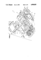
- FIG. 1 is an exploded view of a vehicle body according to an embodiment of the present invention, together with chassis sub-assemblies, upholsteries, etc.;
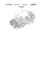
- FIG. 2 is a perspective view of the vehicle body of FIG. 1 in its assembled state
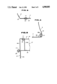
- FIGS. 3 to 13 are enlarged sectional views taken along the lines III--III, IV--IV, V--V, VI--VI, VII--VII, VIII--VIII, IX--IX, X--X, XI--XI, XII--XII and XIII--XIII of FIG. 2, respectively;
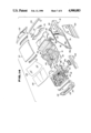
- FIG. 14 is a view similar to FIG. 1 but showing another embodiment of the present invention.
- FIG. 15 is an enlarged exploded view of a principal portion of the vehicle body of FIG. 14.
- a vehicle body according to an embodiment of the present invention is generally indicated by the reference numeral 10 and consists of six separate body sections, i.e., an engine compartment assembly 12, floor assembly 14, rear end assembly 16, a pair of body side assemblies 18 and 18, and a roof assembly 20.
- the engine compartment assembly 12 consists of a dash lower panel 22, cowl box or air box 24 located above the dash lower panel 22 and extending laterally of the vehicle body 10 and a pair of hood ledge panels 26 and 26 extending fowardly from the lateral ends of the dash lower panel 22 and the cowl box 24.
- Each hood ledge panel 26 is formed with a wheel house 28 projecting laterally inwardly of the vehicle body 10.
- a pair of longitudinal members 30 and 30 are secured to the lower end portions of the hood ledge panels 26.
- a front cross member 34 spans the longitudinal members 30 and 30 and is secured at the laterally opposed ends to same.
- a reinforcement 32 is secured to the upper end portion of each hood ledge panel 26.
- the reinforcement 32 consists of a reinforcement member 32a secured to the upper end portion of each hood ledge panel 26 and a reinforcement member 32b spanning a cowl box side member 24a and a bracket 36b.
- the cowl box side member 24a is located rearward of each hood ledge panel 26 to cover each lateral end of the cowl box 24.
- the bracket 36b is secured to the lower end portion of a front pillar 36 to project laterally outwards therefrom and adapted to be joined with a rear lateral flange 32d of the reinforcement member 32b by nuts 114 and bolts 116.
- the cowl box 24 is constituted by a dash upper panel 25 and a cowl top grille 27 and so formed as to have a box-like closed section.
- the engine compartment assembly 12 is painted and then equipped with devices and components as an engine 38, radiator 40, battery 42, front axle unit 44, front suspension system 46 and steering linkage (not shown), steering wheel 48, instrument panel 50, etc.
- the engine 38 is installed on the longitudinal members 30 and 30 by way of mounting insulators (not shown).
- the radiator 40 is installed on the front cross member 34.
- the front suspension system 46 includes a pair of struts, though only one 46a is shown, the upper end of each of which is supported on a strut holder 28a provided to each wheel house 28.
- the front suspension system 46 further includes a linkage 46b as a lower link, upper link, etc. which are connected to the longitudinal members 30 and 30.
- the steering wheel 48 is connected, though not shown, to a steering gear which is in turn connected to the steering linkage by way of a steering shaft rotatably supported on a steering column 48a installed on the instrument panel 50.
- the instrument panel 50 is located on the vehicle cabin side of the cowl box 24 and attached to same.
- the floor assembly 14 includes a front floor panel 54 and a rear floor panel 56.
- the front floor panel 54 has at a laterally central portion thereof an upwardly protruded tunnel 54a, and also has at the lateral ends thereof depending flanges 54b and at the rear end thereof an upstanding flange 54c.
- the rear floor panel 56 has a downwardly recessed portion 56a for accomodation of a spare tire.
- the rear floor panel 56 also has at the lateral ends thereof cut or notched portions 56b. Almost all of the peripheral edge of each cut portion 56b and each lateral end of the rear floor panel 56 located more forward than each cut portion 56b are bent upwardly to provide a peripheral flange 56c and a lateral end flange 56d.
- Each lateral end of the rear floor panel 56 located more rearward than each cut portion 56b is provided with a depending rear end flange 56e.
- a rim 56f is provided to extend inwardly from the front end of the rear end flange 56e and downwardly from the rear peripheral portion of the cut portion 56b.
- the rear floor panel 56 has at the rear end thereof an upstanding flange 56g.
- the rear floor panel 56 has at the front end thereof a depending flange 56h.
- the front flange 56h of the rear floor panel 56 and the rear flange 54c of the front floor panel 54 are arranged so as to be spaced a predetermined distance from each other in the longitudinal direction of the vehicle body 10.
- the front flange 56h is secured at the lower end thereof to the upper face of the front floor panel 54 whilst the rear flange 54c is secured at the upper end thereof to the lower face of the rear floor panel 56 so that a laterally elongated box-like closed sectional portion 58 is formed which is effective for assembling the front floor panel 54 and the rear floor panel 56 integrally and rigidly.
- the floor assembly 14 is painted and is equipped with devices, components and upholsteries as a shift lever unit 60, front seats 62, rear seat 64, rear axle unit 66 and, though not shown, spair tire, insulators, carpets, etc.
- the shift lever unit 60 is installed on the tunnel portion 54a.
- the front seats 62 are installed on the opposite sides of the tunnel portion 54a.
- the rear seat 64 is installed on the upper wall of the box-like closed sectional portion 58.
- the rear axle unit 66 is arranged to extend laterally of the vehicle body 10 and installed on the lower face of the rear floor panel 56 by way of a pair of side members 68 and 68.
- the rear end assembly 16 is provided with a rear end panel 70.
- the rear end panel 70 has at the opposite lateral end portions thereof openings 70a and 70a.
- the rear end assembly 16 is painted and equipped with devices and upholsteries as a combination lamp unit 72 installed in the openings 70a and 70a and upholsteries as trim members (not shown).
- Each body side assembly 18 includes a side sill 74, front pillar 36, center pillar 78, rear pillar 80, rear fender 82, roof side rail 84 and a rear wheel house 86.
- the side sill 74 extends longitudinally of the vehicle body 10 and has a box-like closed section.
- the front pillar 36 has a lower end disposed adjacent the front end of the side sill 74 and extends upwardly and rearwardly therefrom whilst the center pillar 78 has a lower end disposed adjacent the intermediate portion of the side sill 74 and extends upwardly therefrom.
- a rear fender 82 is disposed rearward of the lower portion of the center pillar 78 and cooperates with a body side inner panel 90 to form a box-like closed section.
- the rear pillar 80 is disposed rearward of the rear fender 82 to extend upwardly and forwardly therefrom.
- the roof side rail 84 is arranged to interconnect the upper ends of the front, center and rear pillars 76, 78 and 80.
- the body side assembly 18 has an opening 94 surrounded by the roof side rail 84, front pillar 36, center pillar 78 and side sill 74 and an opening 96 surrounded by the roof side rail 84, center pillar 78, rear pillar 80 and the rear fender 82. Though not shown, a front door is adapted to be installed in each opening 94.
- the rear wheel house 86 consists of a wheel house inner 86a projecting inwardly of the vehicle cabin and a wheel house outer (not shown).
- the upper peripheral ends of the wheel house inner 86a and the wheel house outer are joined at a flange 86b which is in turn secured to the periphery of a nearly semicircular cut (not shown) formed in the body side inner panel 90 whilst the lower peripheral edge of the wheel house outer is secured to the peripheral edge of a nearly semi-circular cut 82a formed in the rear fender 82.
- the wheel house outer is joined with the side sill 74 covered by the rear fender 82 in the manner of butt joint.
- Each wheel house inner 86a is formed with a strut holder 86c projecting inwardly of the vehicle cabin.
- the front pillar 36 has at the lower end thereof a dash side panel portion 36a in the form of a lingitudinal flange and a bracket 36b projecting laterally outwardly.
- a pair of brackets 100 and another pair of brackets 102 are respectively provided at the joint between the front pillar 36 and the roof side rail 84 and the joint between the rear pillar 80 and the roof side rail 84.
- the rear fender 82 is provided at the rear end thereof with a bracket 82b projecting laterally inwardly of the vehicle body 10.
- the body side assemblies 18 and 18 are painted and equipped with devices, components and upholsteries as a window glass 104, strut 106, trim members, etc.
- the window glass 104 is installed in the rear opening 96.
- the strut 106 is supported at the upper end thereof upon the strut holder 86c.
- the roof assembly 20 includes a roof panel 108, front roof rail 110 and a rear roof rail 112.
- the roof panel 108 is formed into a nearly square shape and has at each corner portions extensions 108a, 108b, 108c and 108d which are smoothly consecutive with the outer surfaces of the front pillars 36 and 36 and rear pillars 80 and 80.
- the roof panel 108 also has brackets 108e, 108f, 108g and 108h at the front, rear and lateral ends thereof, respectively.
- the front and rear roof rails 110 and 112 are respectively comprised of upper panels and lower panels which are joined to have a box-like closed section and extend laterally of the vehicle body 10.
- the front roof rail 110 is attached to the roof panel 108 by way of the bracket 108e whilst the rear roof rail 112 is by way of the bracket 108f.
- the roof assembly 20 is painted and, though not shown, equipped with devices, components and upholsteries such as a room lamp unit, ceiling member, etc.
- the foregoing vehicle structure is assembled as follows. Firstly, the engine compartment assembly 12, floor assembly 14, rear end assembly 16, body side assembies 18 and 18 and roof assembly 20 are prepared independently, i.e., fabricated and assembled independently. The assemblies are then painted and equipped with devices, components and upholsteries, independently. Then, as shown in FIG. 3, the front end of the front floor panel 54 is placed under the lower end of the dash lower panel 22 and fastened to same with bolts 114 and nuts 116 whilst at the same time, as shown in FIG.
- each reinforcement member 32b is so arranged as to extend between the dash side panel portion 36a and the cowl box side member 24a.
- the reinforcement member 32b, cowl box side member 24a, dash upper panel 25 and the dash side panel portion 36a are fastened together with bolts 114 and nuts 116.
- the lower flange 74a of the side sill 74 is fastened to the lateral end flange 54b of the front floor panel 54 with bolts 114 and nuts 116, which bolts 114 are disposed in place by access thereto from the outside of the vehicle body 10
- the body side inner panel 90 is secured to the lateral end flange 56d of the rear floor panel 56 with bolts 114 and nuts 116, which bolts 114 are disposed in place by access thereto through the access holes 88c.
- the body side inner 90 is also fastened at a portion adjacent the center pillar 78 to the lateral flange 54b of the front floor panel 54 with bolts 114 and nuts 116.
- the lower end of the rear wheel house inner 86a is fastened to the flange 56c at the periphery of the cut portion 56b with bolts 114 and nuts 116 as shown in FIG. 8.
- the lower end of the rear fender 82 is secured to the rear lateral flange 56e of the rear floor panel 56 with bolts 114 and nuts 116 as shown in FIG. 9.
- the rear end assembly 16 is fastened to the flange 82b of the rear fender 82 with bolts 114 and nuts (not shown) as shown in FIG.
- each strut 106 is connected to the rear axle unit 66 of the floor assembly 14. Then, the roof assembly 20 is bolted to the body side assemblies 18 and 18, i.e., as shown in FIG. 1, the lateral end portions of the front roof rail 110 and the rear roof rail 112 are bolted 114 to the brackets 100 and 102 at the front and rear ends of each body side assembly 18, and thereafter as shown in FIGS.
- the brackets 108e, 108f, 108g and 108h of the roof panel 108 are fastened to the front roof rail 110, rear roof rail 112 and roof side rails 84 and 84 with bolts 118 and nuts 120, which bolts 118 are welded to the brackets 108e, 108f, 108g and 108h prior to the assembly and which nuts 120 are disposed in place by access thereto from the inside of the vehicle cabin.
- the foregoing nuts 114 are welded to the corresponding panels prior to the assembly.
- the extension 108c of the roof panel 108 is fastened to the upper portion of the rear pillar 80 with a bolt 114 and a nut 116.
- FIG. 2 the vehicle body shown in FIG. 2 is obtained.
- the vehicle body is then equipped with, though not shown, a front unit including a front bumper, radiator grille, head lamp, etc. and devices and components as a hood, windshield, back door, rear bumper, side doors, front wheels, rear wheels, etc., whereby a two-door sedan hatchback type vehicle is completed.
- a front unit including a front bumper, radiator grille, head lamp, etc. and devices and components as a hood, windshield, back door, rear bumper, side doors, front wheels, rear wheels, etc.
- the cowl box 24 which is partly consituted by the dash upper panel 25 and connected to the dash lower panel 22 is so formed as to have a box-like closed section.
- the dash lower panel 22 is connected at the opposite lateral ends thereof to dash side panels 23 and 23 which are in turn connected at the upper ends thereof to the dash upper panel 25.
- a centralized electronic control unit 29 as a control unit for the engine 38, front suspension 46, head lamp 29, fuse box (not shown), etc. is installed on one of the dash side panels 23 and 23.
- inspection of the engine, suspension, etc. can be performed when the engine compartment assembly 12 is completed. Such inspection can be done with ease and efficiency since all-round access to the engine compartment assembly is attained.
- a front bumper by 124 a front fender, by 126 an engine hood, by 128 a windshield, by 130 a front door, by 132 a back door and by 134 a rear bumper. These are installed in place at the final stage of the assembly.
- the vehicle body structure modularized according to the present invention makes it possible to attain installation and inspection of equipments as an engine, suspension, electronic control system therefor, etc. with ease and efficiency since the assemblies are accessible from all sides thereof, i.e., all-round access to each assemblies is available.
- vehicle body structure is suited for assembly using robots since the robots can be less simple not only in operation or movement but in structure of themselves.
- equipments of each assembly e.g., equipments of the engine compartment assembly as the engine, suspension, steering, brake, etc. can be subjected to inspection prior to assembly thereof with other assemblies, faults can be found for repairment and replacement at an early stage of the assembly.
- vehicle body structure of this invention makes it possible to attain various types of vehicles with ease and efficiency since each vehicle body assembly is replaceable with another kind.
- the present invention has been described and shown as above, this is not limitative.
- the present invention is not limited to a vehicle of a two-door sedan hatchback type but can be applied to various types other than the type shown.
Landscapes
- Engineering & Computer Science (AREA)
- Chemical & Material Sciences (AREA)
- Combustion & Propulsion (AREA)
- Transportation (AREA)
- Mechanical Engineering (AREA)
- Manufacturing & Machinery (AREA)
- Body Structure For Vehicles (AREA)
Abstract
Description
Claims (1)
Applications Claiming Priority (4)
| Application Number | Priority Date | Filing Date | Title |
|---|---|---|---|
| JP62-46112[U] | 1987-03-27 | ||
| JP4611287U JPH0630604Y2 (en) | 1987-03-27 | 1987-03-27 | Car body structure |
| JP62-78046 | 1987-03-31 | ||
| JP62078046A JP2501818B2 (en) | 1987-03-31 | 1987-03-31 | How to assemble a car body |
Publications (1)
| Publication Number | Publication Date |
|---|---|
| US4900083A true US4900083A (en) | 1990-02-13 |
Family
ID=26386235
Family Applications (1)
| Application Number | Title | Priority Date | Filing Date |
|---|---|---|---|
| US07/171,813 Expired - Lifetime US4900083A (en) | 1987-03-27 | 1988-03-22 | Modular vehicle body and method of building same |
Country Status (3)
| Country | Link |
|---|---|
| US (1) | US4900083A (en) |
| DE (1) | DE3809456C2 (en) |
| GB (1) | GB2204000B (en) |
Cited By (52)
| Publication number | Priority date | Publication date | Assignee | Title |
|---|---|---|---|---|
| US4968087A (en) * | 1988-04-22 | 1990-11-06 | Fiat Auto S.P.A. | Method for the assembly of various versions of motor-car body structures and body structures produced by this method |
| US5129700A (en) * | 1989-12-18 | 1992-07-14 | Fiat Auto S.P.A. | Body for a motor vehicle |
| US5213386A (en) * | 1992-05-11 | 1993-05-25 | Ford Motor Company | Space frame construction |
| US5288356A (en) * | 1988-12-22 | 1994-02-22 | Basf Corporation | Method of making a coated article |
| US5332281A (en) * | 1992-04-30 | 1994-07-26 | Ford Motor Company | Space frame construction |
| US5488770A (en) * | 1991-04-26 | 1996-02-06 | Hitachi, Ltd. | Method of producing a vehicle body |
| US5609386A (en) * | 1994-07-21 | 1997-03-11 | Honda Giken Kogyo Kabushiki Kaisha | Structure of frame connecting portion in vehicle |
| WO1997012800A1 (en) * | 1995-10-06 | 1997-04-10 | Chrysler Corporation | Motor vehicle body |
| US5666727A (en) * | 1995-02-17 | 1997-09-16 | General Motors Corporation | Method of manufacturing a passenger compartment from a cylindrical tube |
| US5860694A (en) * | 1994-03-01 | 1999-01-19 | Mercedes-Benz Ag | Integral bodyshell structure for a motor vehicle and method of producing the bodyshell structure |
| US5934397A (en) * | 1997-01-28 | 1999-08-10 | Schaper; Douglas | Modular land vehicle |
| US6012765A (en) * | 1996-10-24 | 2000-01-11 | Freightliner Corporation | Truck door frame and door installation assembly |
| US6105231A (en) * | 1995-07-26 | 2000-08-22 | Clare; Scott | Hidden storage/utility system modular fabrication method |
| EP1048553A2 (en) * | 1999-04-29 | 2000-11-02 | Webasto Vehicle Systems International GmbH | Vehicle roof with incorporated roof unit and assembly method thereof |
| US6155634A (en) * | 1997-06-02 | 2000-12-05 | Volkswagen Ag | Body frame component for a motor vehicle and method of producing it |
| US6220654B1 (en) * | 1997-02-28 | 2001-04-24 | Ulrich Sommer | Passenger car |
| US6237211B1 (en) * | 1995-07-26 | 2001-05-29 | Scott Clare | Modular fabrication and assembly method for vehicle hidden storage systems |
| US6334645B1 (en) * | 1999-10-29 | 2002-01-01 | Nissan Motor Co., Ltd. | Structure of front end portion of front fender in vehicle |
| CN1078552C (en) * | 1994-10-26 | 2002-01-30 | 诺贝特·巴斯勒 | Process for building motor vehicles |
| US6375247B1 (en) * | 2000-04-13 | 2002-04-23 | General Motors Corporation | Body of a motor vehicle with a seat module |
| WO2002046026A1 (en) * | 2000-12-07 | 2002-06-13 | Ise Innomotive Systems Europe Gmbh | Rear end module for passenger motor vehicles |
| US6493920B1 (en) * | 2000-09-07 | 2002-12-17 | Ford Global Technologies, Inc. | Method of assembling a vehicle from preassembled modular components |
| US6499795B2 (en) | 1995-07-26 | 2002-12-31 | Scott Clare | Vehicle with storage/utility system |
| US6502895B2 (en) * | 2001-02-23 | 2003-01-07 | International Truck Intellectual Property Company, L.L.C. | Unitized bus vehicle roof |
| US20030037970A1 (en) * | 2001-08-23 | 2003-02-27 | Chernoff Adrian B. | Vehicle chassis having systems responsive to non-mechanical control signals |
| US20030141746A1 (en) * | 2002-01-26 | 2003-07-31 | Dr. Ing. H.C.F. Porsche Ag | Body of a motor vehicle |
| US6757958B1 (en) * | 2000-05-11 | 2004-07-06 | Jlg Omniquip, Inc. | Load handler with modular frame assembly |
| GB2404173A (en) * | 2003-07-19 | 2005-01-26 | Linde Ag | Force introduction node on a frame section formed as a hollow profile |
| EP1524176A1 (en) * | 2003-10-17 | 2005-04-20 | Dana Corporation | Method of manufacturing a frame assembly |
| US6896319B1 (en) | 2003-12-01 | 2005-05-24 | General Motors Corporation | Vehicle modular body and method of assembly thereof |
| US20050230934A1 (en) * | 2004-04-02 | 2005-10-20 | Wilt H William B | Method of making a modular vehicle and a modular vehicle |
| US20060133906A1 (en) * | 2004-12-17 | 2006-06-22 | Wilt H W B | Transport vehicle with loading channel that extends for the entire length of the vehicle |
| US20070062751A1 (en) * | 2003-12-15 | 2007-03-22 | Bombardier Recreational Products Inc. | Modular Snowmobile Platform |
| US7267394B1 (en) | 2004-06-03 | 2007-09-11 | Ford Global Technologies, Llc | Front end tubular structure for unitized body vehicles |
| US20080169679A1 (en) * | 2007-01-11 | 2008-07-17 | Ford Motor Company | Vehicle having a passenger compartment body structure |
| US20080169665A1 (en) * | 2007-01-11 | 2008-07-17 | Ford Motor Company | Vehicle having a passenger compartment body structure |
| US20080169685A1 (en) * | 2007-01-11 | 2008-07-17 | Ford Motor Company | Vehicle body component and mating feature |
| US20080169666A1 (en) * | 2007-01-11 | 2008-07-17 | Ford Motor Company | Vehicle having a body panel |
| US20080168644A1 (en) * | 2007-01-11 | 2008-07-17 | Ford Motor Company | Method of manufacturing a vehicle |
| US20080185872A1 (en) * | 2007-02-01 | 2008-08-07 | Magna International Inc. | Component integration panel system with closed box section |
| US20080201952A1 (en) * | 2007-01-11 | 2008-08-28 | Ford Motor Company | Method of manufacturing a vehicle |
| CN100434326C (en) * | 2005-11-21 | 2008-11-19 | 本田技研工业株式会社 | Rear vehicle body structure |
| US7461884B2 (en) | 1995-07-26 | 2008-12-09 | Scott Clare | Storage system for vehicles |
| US20090243270A1 (en) * | 2008-03-27 | 2009-10-01 | Frederic Defoy | Vehicle frame with stress relief feature |
| US20090260215A1 (en) * | 2008-04-22 | 2009-10-22 | Dr.Ing.H.C.F.Porsche Aktiengesellschaft | Method for the manufacture of motor vehicles |
| US20100176622A1 (en) * | 2009-01-13 | 2010-07-15 | Magna Car Top Systems Gmbh | Method of providing a vehicle body with one of four different tops |
| US20110049934A1 (en) * | 2008-06-10 | 2011-03-03 | Toyota Shatai Kabushiki Kaisha | Structure for fixing fender panel in car |
| US20110133518A1 (en) * | 2009-12-03 | 2011-06-09 | GM Global Technology Operations LLC | Chassis structure of a motor vehicle body |
| US20140062136A1 (en) * | 2012-09-06 | 2014-03-06 | GM Global Technology Operations LLC | Laser welded structural fender inner blank for mass optimization |
| US9771108B2 (en) * | 2015-08-03 | 2017-09-26 | Ford Global Technologies, Llc | Vehicle body assembly and method of joining vehicle body components |
| CN114889707A (en) * | 2022-04-06 | 2022-08-12 | 北京汽车集团越野车有限公司 | Vehicle body structure, vehicle and assembly method of vehicle body structure |
| WO2024182432A1 (en) * | 2023-02-28 | 2024-09-06 | Tesla, Inc. | Modular vehicle architecture for assembling vehicles |
Families Citing this family (16)
| Publication number | Priority date | Publication date | Assignee | Title |
|---|---|---|---|---|
| DE3903062A1 (en) * | 1989-02-02 | 1990-08-16 | Hommel M & A Gmbh | Vehicle for transporting passengers by road, by rail, on water or in the air |
| DE4228120A1 (en) * | 1992-08-25 | 1994-03-03 | Opel Adam Ag | Modular motor vehicle |
| US5881458A (en) * | 1995-12-14 | 1999-03-16 | Dr. Ing. H.C.F. Porsche Ag | Process for manufacturing a body structure for a convertible |
| DE19621451A1 (en) * | 1996-05-29 | 1997-12-04 | Teves Gmbh Alfred | Motor vehicle in a modular design |
| US6862809B2 (en) | 1998-06-18 | 2005-03-08 | Alcan Technology & Management Ltd. | Manufacturing process of roof unit and basic structure of a road-bound vehicle |
| CH692783A8 (en) * | 1998-06-18 | 2003-01-15 | Alcan Tech & Man Ag | Roof group and floor group of a road vehicle. |
| US6860014B2 (en) | 1998-06-18 | 2005-03-01 | Alcan Technology & Management Ltd. | Roof unit and basic structure of a road-bound vehicle |
| US7076877B2 (en) | 1998-06-18 | 2006-07-18 | Alcan Technology & Management, Ltd. | Roof unit and floor unit for a road vehicle |
| US6623068B2 (en) | 1998-06-18 | 2003-09-23 | Alcan Technology & Management Ag | Roof unit and basic structure of a road-bound vehicle |
| GB2378157A (en) * | 2001-08-01 | 2003-02-05 | Land Rover Uk Ltd | Vehicle construction |
| DE10260913A1 (en) * | 2002-12-20 | 2004-07-01 | Volkswagen Ag | Automobile body has multi-section frame structure with each individual frame module having at least one additional flat surface element providing stability |
| DE102004035530B4 (en) * | 2004-07-22 | 2020-08-13 | Bayerische Motoren Werke Aktiengesellschaft | Vehicle body with at least one front end and one passenger cell |
| FR2910430A3 (en) * | 2006-12-22 | 2008-06-27 | Renault Sas | Two parts e.g. tunnel, assembling method for motor vehicle, involves positioning tunnel and sub tunnel crosshead in orifices by penetration of screw, and integrating crosshead with tunnel by setting tunnel and crosshead on screw |
| DE102008055738A1 (en) * | 2008-11-04 | 2010-05-06 | Daimler Ag | Module system for manufacturing body of car i.e. saloon car, has front car modules, main base modules and rear modules that are connected with each other by adapter component, and rear seat cross beam integrated into main base modules |
| DE102010034939A1 (en) * | 2010-08-20 | 2012-02-23 | Gm Global Technology Operations Llc (N.D.Ges.D. Staates Delaware) | Motor car body, has bracket plate arranged between lateral front wall and outer sidewall, extending in transverse direction of body and comprising two flanges connected with front wall and sidewall, respectively |
| DE102019214260A1 (en) * | 2019-09-19 | 2021-03-25 | Volkswagen Aktiengesellschaft | Method for manufacturing a vehicle and process arrangement |
Citations (29)
| Publication number | Priority date | Publication date | Assignee | Title |
|---|---|---|---|---|
| US2389907A (en) * | 1941-12-09 | 1945-11-27 | Midland Steel Prod Co | Vehicle structure |
| GB626305A (en) * | 1945-04-23 | 1949-07-13 | Aluminium Francais | Improvements in assembling metallic vehicle bodies by spot welding |
| GB701413A (en) * | 1950-11-29 | 1953-12-23 | Willy Messerschmitt | Improvements relating to road vehicle construction |
| US2700570A (en) * | 1948-12-30 | 1955-01-25 | Barenyi Bela | Motor vehicle of three-section, separably connected type |
| GB737655A (en) * | 1951-11-01 | 1955-09-28 | Mulliners Ltd | Improvements in motor vehicle bodies |
| US2988397A (en) * | 1955-09-24 | 1961-06-13 | Citroen Sa Andre | Motor vehicle bodies |
| US3021172A (en) * | 1957-07-05 | 1962-02-13 | Daimler Benz Ag | Self-supporting vehicle body |
| US3022105A (en) * | 1959-09-21 | 1962-02-20 | Tjaarda John | Composite automobile design |
| US3541668A (en) * | 1967-12-01 | 1970-11-24 | Budd Co | Method of assembling a unitized vehicle body |
| US3882592A (en) * | 1974-03-05 | 1975-05-13 | Pritchard King Inc | Method of assemblying a truck body |
| DE3119666A1 (en) * | 1980-05-19 | 1982-01-14 | Fiat Auto S.p.A., 10100 Torino | Load-bearing vehicle body |
| DE3035333A1 (en) * | 1980-09-19 | 1982-05-06 | Daimler-Benz Ag, 7000 Stuttgart | Corrosion resistant car body - has central shell of cast alloy with bolt on crush zones and plastics panels |
| US4332012A (en) * | 1978-11-27 | 1982-05-25 | Nissan Motor Company, Limited | Control system for automotive vehicle component assembly lines |
| EP0127225A2 (en) * | 1983-05-25 | 1984-12-05 | RENAULT ITALIA S.p.A. | Vehicle structure and assembling method therefor |
| EP0142581A1 (en) * | 1981-07-06 | 1985-05-29 | Paul F. Bonfilio | Motor vehicle having modular chassis and body |
| DE3413228A1 (en) * | 1984-04-07 | 1985-10-31 | Audi AG, 8070 Ingolstadt | Method for manufacturing a vehicle body and central pillar of a vehicle body manufactured according to the method |
| EP0178266A1 (en) * | 1984-10-01 | 1986-04-16 | FIAT AUTO S.p.A. | Motor vehicle including a preassembled subassembly formed by the power unit and a series of components of the systems of the vehicle |
| DE3536015A1 (en) * | 1984-10-16 | 1986-04-24 | Volkswagen AG, 3180 Wolfsburg | Manufacturing station, in particular for motor vehicle bodies |
| EP0180554A1 (en) * | 1984-11-02 | 1986-05-07 | FIAT AUTO S.p.A. | Method of assembling motor vehicle bodies for the production of bodies of different types, and a body obtained by this method |
| US4590654A (en) * | 1983-12-23 | 1986-05-27 | Nissan Motor Company, Limited | Method for controlling automotive vehicle assembly and a system performing the method |
| WO1987003846A1 (en) * | 1985-12-23 | 1987-07-02 | Libbey-Owens-Ford Co. | Method of assembling a vehicle from modular components |
| GB2187683A (en) * | 1986-03-14 | 1987-09-16 | American Motors Corp | Modular vehicle construction and assembly method |
| EP0240470A1 (en) * | 1986-03-24 | 1987-10-07 | FIAT AUTO S.p.A. | Motor vehicle with a load-bearing platform and body with elements of plastics material, and a method for its manufacture |
| EP0256931A1 (en) * | 1986-08-06 | 1988-02-24 | Automobiles Peugeot | Modular assembly of an automobile vehicle |
| US4759489A (en) * | 1986-06-24 | 1988-07-26 | Litton U.K. Limited | Automobile body building methods and apparatus |
| JPH06288676A (en) * | 1993-04-05 | 1994-10-18 | Iseki & Co Ltd | Dehumidification and drying device for grains |
| JPH06288674A (en) * | 1993-03-31 | 1994-10-18 | Tokin Corp | Dryer |
| JPH06288675A (en) * | 1993-04-05 | 1994-10-18 | Kaneko Agricult Mach Co Ltd | Grain drying device in grain storage bin |
| JPH06288678A (en) * | 1992-04-27 | 1994-10-18 | Kawasaki Heavy Ind Ltd | Melting furnace and melting plant |
-
1988
- 1988-03-21 DE DE3809456A patent/DE3809456C2/en not_active Expired - Lifetime
- 1988-03-22 US US07/171,813 patent/US4900083A/en not_active Expired - Lifetime
- 1988-03-23 GB GB8806907A patent/GB2204000B/en not_active Expired - Lifetime
Patent Citations (30)
| Publication number | Priority date | Publication date | Assignee | Title |
|---|---|---|---|---|
| US2389907A (en) * | 1941-12-09 | 1945-11-27 | Midland Steel Prod Co | Vehicle structure |
| GB626305A (en) * | 1945-04-23 | 1949-07-13 | Aluminium Francais | Improvements in assembling metallic vehicle bodies by spot welding |
| US2700570A (en) * | 1948-12-30 | 1955-01-25 | Barenyi Bela | Motor vehicle of three-section, separably connected type |
| GB701413A (en) * | 1950-11-29 | 1953-12-23 | Willy Messerschmitt | Improvements relating to road vehicle construction |
| GB737655A (en) * | 1951-11-01 | 1955-09-28 | Mulliners Ltd | Improvements in motor vehicle bodies |
| US2988397A (en) * | 1955-09-24 | 1961-06-13 | Citroen Sa Andre | Motor vehicle bodies |
| US3021172A (en) * | 1957-07-05 | 1962-02-13 | Daimler Benz Ag | Self-supporting vehicle body |
| US3022105A (en) * | 1959-09-21 | 1962-02-20 | Tjaarda John | Composite automobile design |
| US3541668A (en) * | 1967-12-01 | 1970-11-24 | Budd Co | Method of assembling a unitized vehicle body |
| US3882592A (en) * | 1974-03-05 | 1975-05-13 | Pritchard King Inc | Method of assemblying a truck body |
| US4332012A (en) * | 1978-11-27 | 1982-05-25 | Nissan Motor Company, Limited | Control system for automotive vehicle component assembly lines |
| DE3119666A1 (en) * | 1980-05-19 | 1982-01-14 | Fiat Auto S.p.A., 10100 Torino | Load-bearing vehicle body |
| DE3035333A1 (en) * | 1980-09-19 | 1982-05-06 | Daimler-Benz Ag, 7000 Stuttgart | Corrosion resistant car body - has central shell of cast alloy with bolt on crush zones and plastics panels |
| EP0142581A1 (en) * | 1981-07-06 | 1985-05-29 | Paul F. Bonfilio | Motor vehicle having modular chassis and body |
| EP0127225A2 (en) * | 1983-05-25 | 1984-12-05 | RENAULT ITALIA S.p.A. | Vehicle structure and assembling method therefor |
| US4590654A (en) * | 1983-12-23 | 1986-05-27 | Nissan Motor Company, Limited | Method for controlling automotive vehicle assembly and a system performing the method |
| DE3413228A1 (en) * | 1984-04-07 | 1985-10-31 | Audi AG, 8070 Ingolstadt | Method for manufacturing a vehicle body and central pillar of a vehicle body manufactured according to the method |
| EP0178266A1 (en) * | 1984-10-01 | 1986-04-16 | FIAT AUTO S.p.A. | Motor vehicle including a preassembled subassembly formed by the power unit and a series of components of the systems of the vehicle |
| DE3536015A1 (en) * | 1984-10-16 | 1986-04-24 | Volkswagen AG, 3180 Wolfsburg | Manufacturing station, in particular for motor vehicle bodies |
| EP0180554A1 (en) * | 1984-11-02 | 1986-05-07 | FIAT AUTO S.p.A. | Method of assembling motor vehicle bodies for the production of bodies of different types, and a body obtained by this method |
| WO1987003846A1 (en) * | 1985-12-23 | 1987-07-02 | Libbey-Owens-Ford Co. | Method of assembling a vehicle from modular components |
| US4730870A (en) * | 1986-03-14 | 1988-03-15 | American Motors Corporation | Modular vehicle construction and assembly method |
| GB2187683A (en) * | 1986-03-14 | 1987-09-16 | American Motors Corp | Modular vehicle construction and assembly method |
| EP0240470A1 (en) * | 1986-03-24 | 1987-10-07 | FIAT AUTO S.p.A. | Motor vehicle with a load-bearing platform and body with elements of plastics material, and a method for its manufacture |
| US4759489A (en) * | 1986-06-24 | 1988-07-26 | Litton U.K. Limited | Automobile body building methods and apparatus |
| EP0256931A1 (en) * | 1986-08-06 | 1988-02-24 | Automobiles Peugeot | Modular assembly of an automobile vehicle |
| JPH06288678A (en) * | 1992-04-27 | 1994-10-18 | Kawasaki Heavy Ind Ltd | Melting furnace and melting plant |
| JPH06288674A (en) * | 1993-03-31 | 1994-10-18 | Tokin Corp | Dryer |
| JPH06288676A (en) * | 1993-04-05 | 1994-10-18 | Iseki & Co Ltd | Dehumidification and drying device for grains |
| JPH06288675A (en) * | 1993-04-05 | 1994-10-18 | Kaneko Agricult Mach Co Ltd | Grain drying device in grain storage bin |
Non-Patent Citations (1)
| Title |
|---|
| Automotive Industries, Feb., 1986. * |
Cited By (77)
| Publication number | Priority date | Publication date | Assignee | Title |
|---|---|---|---|---|
| US4968087A (en) * | 1988-04-22 | 1990-11-06 | Fiat Auto S.P.A. | Method for the assembly of various versions of motor-car body structures and body structures produced by this method |
| US5288356A (en) * | 1988-12-22 | 1994-02-22 | Basf Corporation | Method of making a coated article |
| US5129700A (en) * | 1989-12-18 | 1992-07-14 | Fiat Auto S.P.A. | Body for a motor vehicle |
| US5488770A (en) * | 1991-04-26 | 1996-02-06 | Hitachi, Ltd. | Method of producing a vehicle body |
| US5332281A (en) * | 1992-04-30 | 1994-07-26 | Ford Motor Company | Space frame construction |
| US5549352A (en) * | 1992-04-30 | 1996-08-27 | Ford Motor Company | Split joint construction for a space frame |
| US5213386A (en) * | 1992-05-11 | 1993-05-25 | Ford Motor Company | Space frame construction |
| US5860694A (en) * | 1994-03-01 | 1999-01-19 | Mercedes-Benz Ag | Integral bodyshell structure for a motor vehicle and method of producing the bodyshell structure |
| US5609386A (en) * | 1994-07-21 | 1997-03-11 | Honda Giken Kogyo Kabushiki Kaisha | Structure of frame connecting portion in vehicle |
| CN1078552C (en) * | 1994-10-26 | 2002-01-30 | 诺贝特·巴斯勒 | Process for building motor vehicles |
| US5666727A (en) * | 1995-02-17 | 1997-09-16 | General Motors Corporation | Method of manufacturing a passenger compartment from a cylindrical tube |
| US6237211B1 (en) * | 1995-07-26 | 2001-05-29 | Scott Clare | Modular fabrication and assembly method for vehicle hidden storage systems |
| US6105231A (en) * | 1995-07-26 | 2000-08-22 | Clare; Scott | Hidden storage/utility system modular fabrication method |
| US7461884B2 (en) | 1995-07-26 | 2008-12-09 | Scott Clare | Storage system for vehicles |
| US6499795B2 (en) | 1995-07-26 | 2002-12-31 | Scott Clare | Vehicle with storage/utility system |
| US7104583B2 (en) | 1995-07-26 | 2006-09-12 | Scott Clare | Vehicle with storage/utility system |
| WO1997012800A1 (en) * | 1995-10-06 | 1997-04-10 | Chrysler Corporation | Motor vehicle body |
| US5934745A (en) * | 1995-10-06 | 1999-08-10 | Daimlerchrysler Corporation | Motor vehicle body |
| US6012765A (en) * | 1996-10-24 | 2000-01-11 | Freightliner Corporation | Truck door frame and door installation assembly |
| US5934397A (en) * | 1997-01-28 | 1999-08-10 | Schaper; Douglas | Modular land vehicle |
| US6220654B1 (en) * | 1997-02-28 | 2001-04-24 | Ulrich Sommer | Passenger car |
| US6155634A (en) * | 1997-06-02 | 2000-12-05 | Volkswagen Ag | Body frame component for a motor vehicle and method of producing it |
| EP1048553A3 (en) * | 1999-04-29 | 2002-03-27 | Webasto Vehicle Systems International GmbH | Vehicle roof with incorporated roof unit and assembly method thereof |
| EP1048553A2 (en) * | 1999-04-29 | 2000-11-02 | Webasto Vehicle Systems International GmbH | Vehicle roof with incorporated roof unit and assembly method thereof |
| US6334645B1 (en) * | 1999-10-29 | 2002-01-01 | Nissan Motor Co., Ltd. | Structure of front end portion of front fender in vehicle |
| US6375247B1 (en) * | 2000-04-13 | 2002-04-23 | General Motors Corporation | Body of a motor vehicle with a seat module |
| US6757958B1 (en) * | 2000-05-11 | 2004-07-06 | Jlg Omniquip, Inc. | Load handler with modular frame assembly |
| US20070071587A1 (en) * | 2000-05-11 | 2007-03-29 | Jlg Omniquip, Inc. | Modular frame load handler with translatable boom carriage |
| US7390021B2 (en) | 2000-05-11 | 2008-06-24 | Jlg Omniquip, Inc. | Modular frame load handler with translatable boom carriage |
| US6493920B1 (en) * | 2000-09-07 | 2002-12-17 | Ford Global Technologies, Inc. | Method of assembling a vehicle from preassembled modular components |
| US20040066061A1 (en) * | 2000-12-07 | 2004-04-08 | Frank Engels | Rear end module for passenger motor vehicles |
| US6846037B2 (en) * | 2000-12-07 | 2005-01-25 | Ise Innomotive Systems Europe Gmbh | Rear end module for passenger motor vehicles |
| WO2002046026A1 (en) * | 2000-12-07 | 2002-06-13 | Ise Innomotive Systems Europe Gmbh | Rear end module for passenger motor vehicles |
| US6502895B2 (en) * | 2001-02-23 | 2003-01-07 | International Truck Intellectual Property Company, L.L.C. | Unitized bus vehicle roof |
| US20030037970A1 (en) * | 2001-08-23 | 2003-02-27 | Chernoff Adrian B. | Vehicle chassis having systems responsive to non-mechanical control signals |
| US6817656B2 (en) * | 2002-01-26 | 2004-11-16 | Dr. Ing. H.C.F. Porsche Ag | Body of a motor vehicle |
| US20030141746A1 (en) * | 2002-01-26 | 2003-07-31 | Dr. Ing. H.C.F. Porsche Ag | Body of a motor vehicle |
| GB2404173A (en) * | 2003-07-19 | 2005-01-26 | Linde Ag | Force introduction node on a frame section formed as a hollow profile |
| GB2404173B (en) * | 2003-07-19 | 2006-06-07 | Linde Ag | Force introduction node on a frame section formed with a hollow profile |
| US20050116460A1 (en) * | 2003-10-17 | 2005-06-02 | Mcgill Scott M. | Method of manufacturing a frame assembly |
| EP1524176A1 (en) * | 2003-10-17 | 2005-04-20 | Dana Corporation | Method of manufacturing a frame assembly |
| US20050116506A1 (en) * | 2003-12-01 | 2005-06-02 | Huang Yueh-Se (. | Vehicle modular body and method of assembly thereof |
| US6896319B1 (en) | 2003-12-01 | 2005-05-24 | General Motors Corporation | Vehicle modular body and method of assembly thereof |
| US20070062751A1 (en) * | 2003-12-15 | 2007-03-22 | Bombardier Recreational Products Inc. | Modular Snowmobile Platform |
| US8074759B2 (en) | 2003-12-15 | 2011-12-13 | Bombardier Recreational Products Inc. | Method of assembling a modular snowmobile platform |
| US20100288574A1 (en) * | 2003-12-15 | 2010-11-18 | Bombardier Recreational Products, Inc. | Modular Snowmobile Platform |
| US20050230934A1 (en) * | 2004-04-02 | 2005-10-20 | Wilt H William B | Method of making a modular vehicle and a modular vehicle |
| US7267394B1 (en) | 2004-06-03 | 2007-09-11 | Ford Global Technologies, Llc | Front end tubular structure for unitized body vehicles |
| US20060133906A1 (en) * | 2004-12-17 | 2006-06-22 | Wilt H W B | Transport vehicle with loading channel that extends for the entire length of the vehicle |
| CN100434326C (en) * | 2005-11-21 | 2008-11-19 | 本田技研工业株式会社 | Rear vehicle body structure |
| US20080169666A1 (en) * | 2007-01-11 | 2008-07-17 | Ford Motor Company | Vehicle having a body panel |
| US7850226B2 (en) | 2007-01-11 | 2010-12-14 | Ford Motor Company | Vehicle having a passenger compartment body structure |
| US20080201952A1 (en) * | 2007-01-11 | 2008-08-28 | Ford Motor Company | Method of manufacturing a vehicle |
| US20080168644A1 (en) * | 2007-01-11 | 2008-07-17 | Ford Motor Company | Method of manufacturing a vehicle |
| US20080169685A1 (en) * | 2007-01-11 | 2008-07-17 | Ford Motor Company | Vehicle body component and mating feature |
| US8038205B2 (en) * | 2007-01-11 | 2011-10-18 | Ford Motor Company | Vehicle having a passenger compartment body structure |
| US20080169679A1 (en) * | 2007-01-11 | 2008-07-17 | Ford Motor Company | Vehicle having a passenger compartment body structure |
| US8123284B2 (en) | 2007-01-11 | 2012-02-28 | Ford Motor Company | Vehicle body component and mating feature |
| US8317964B2 (en) | 2007-01-11 | 2012-11-27 | Ford Motor Company | Method of manufacturing a vehicle |
| US20080169665A1 (en) * | 2007-01-11 | 2008-07-17 | Ford Motor Company | Vehicle having a passenger compartment body structure |
| US8177277B2 (en) | 2007-01-11 | 2012-05-15 | Ford Motor Company | Vehicle having a body panel |
| US7849601B2 (en) | 2007-01-11 | 2010-12-14 | Ford Motor Company | Method of manufacturing a vehicle |
| US20080185872A1 (en) * | 2007-02-01 | 2008-08-07 | Magna International Inc. | Component integration panel system with closed box section |
| US7571957B2 (en) * | 2007-02-01 | 2009-08-11 | Magna International | Component integration panel system with closed box section |
| US8070216B2 (en) * | 2008-03-27 | 2011-12-06 | Nova Bus, Division De Groupe Volvo Canada Inc. | Vehicle frame with stress relief feature |
| US20090243270A1 (en) * | 2008-03-27 | 2009-10-01 | Frederic Defoy | Vehicle frame with stress relief feature |
| US20090260215A1 (en) * | 2008-04-22 | 2009-10-22 | Dr.Ing.H.C.F.Porsche Aktiengesellschaft | Method for the manufacture of motor vehicles |
| US8844109B2 (en) * | 2008-04-22 | 2014-09-30 | Dr. Ing.h.c.F.Porsche Aktiengesellschaft | Method for the manufacture of motor vehicles |
| US7988227B2 (en) * | 2008-06-10 | 2011-08-02 | Toyota Shatai Kabushiki Kaisha | Structure for fixing fender panel in car |
| US20110049934A1 (en) * | 2008-06-10 | 2011-03-03 | Toyota Shatai Kabushiki Kaisha | Structure for fixing fender panel in car |
| US20100176622A1 (en) * | 2009-01-13 | 2010-07-15 | Magna Car Top Systems Gmbh | Method of providing a vehicle body with one of four different tops |
| US20110133518A1 (en) * | 2009-12-03 | 2011-06-09 | GM Global Technology Operations LLC | Chassis structure of a motor vehicle body |
| US8714636B2 (en) * | 2009-12-03 | 2014-05-06 | GM Global Technology Operations LLC | Chassis structure of a motor vehicle body |
| US20140062136A1 (en) * | 2012-09-06 | 2014-03-06 | GM Global Technology Operations LLC | Laser welded structural fender inner blank for mass optimization |
| US9771108B2 (en) * | 2015-08-03 | 2017-09-26 | Ford Global Technologies, Llc | Vehicle body assembly and method of joining vehicle body components |
| CN114889707A (en) * | 2022-04-06 | 2022-08-12 | 北京汽车集团越野车有限公司 | Vehicle body structure, vehicle and assembly method of vehicle body structure |
| WO2024182432A1 (en) * | 2023-02-28 | 2024-09-06 | Tesla, Inc. | Modular vehicle architecture for assembling vehicles |
Also Published As
| Publication number | Publication date |
|---|---|
| GB2204000B (en) | 1991-05-01 |
| DE3809456C2 (en) | 1995-06-14 |
| GB2204000A (en) | 1988-11-02 |
| DE3809456A1 (en) | 1988-10-13 |
| GB8806907D0 (en) | 1988-04-27 |
Similar Documents
| Publication | Publication Date | Title |
|---|---|---|
| US4900083A (en) | Modular vehicle body and method of building same | |
| US11524736B2 (en) | Method of assembling vehicle including an integrated interior module and top-hat | |
| US4881756A (en) | Vehicle structure, especially chassis frame structure | |
| US4883310A (en) | Roof structure for modular vehicle body | |
| US5090105A (en) | Modular vehicle construction and assembly method | |
| US4914802A (en) | Method of assembling automotive body structure having pre-assembled inner cover member on each body unit. | |
| US4978164A (en) | Modular vehicle body structure | |
| US4730870A (en) | Modular vehicle construction and assembly method | |
| US4836600A (en) | Floor structure for modular vehicle body | |
| US5018781A (en) | Roof structure for modular vehicle body and method of building same | |
| US8641133B1 (en) | High strength lightweight vehicle and an improved method for producing same | |
| US6315351B1 (en) | Cabin structure for medium truck and truck | |
| CZ286839B6 (en) | Process for producing a vehicle and half-finished product employed in this manufacturing process | |
| JP2501818B2 (en) | How to assemble a car body | |
| JP2506734B2 (en) | Car body structure | |
| JP2566582Y2 (en) | Module assembly structure for vehicle body | |
| JPS63235175A (en) | Body structure of vehicle | |
| JPS63235177A (en) | Fixing structure of rear parcel panel | |
| JPH0517349Y2 (en) | ||
| JPH0815871B2 (en) | How to assemble a car body | |
| JP2760537B2 (en) | Automobile manufacturing method | |
| JPH05246349A (en) | Manufacture of automobile | |
| JPS63242779A (en) | Roof mounting structure for automobile | |
| JPS63242776A (en) | Car body assembling method for automobile | |
| JPS6192965A (en) | Car body structure |
Legal Events
| Date | Code | Title | Description |
|---|---|---|---|
| AS | Assignment |
Owner name: NISSAN MOTOR CO., LTD.,JAPAN Free format text: ASSIGNMENT OF ASSIGNORS INTEREST;ASSIGNORS:KUMASAKA, HIDEYUKI;HAGIWARA, TAROU;NAKAMURA, KATSUMI;AND OTHERS;SIGNING DATES FROM 19880103 TO 19880403;REEL/FRAME:004856/0337 Owner name: NISSAN MOTOR CO., LTD., NO. 2, TAKARA-CHO, KANAGAW Free format text: ASSIGNMENT OF ASSIGNORS INTEREST.;ASSIGNORS:KUMASAKA, HIDEYUKI;HAGIWARA, TAROU;NAKAMURA, KATSUMI;AND OTHERS;REEL/FRAME:004856/0337;SIGNING DATES FROM 19880103 TO 19880403 |
|
| STCF | Information on status: patent grant |
Free format text: PATENTED CASE |
|
| FEPP | Fee payment procedure |
Free format text: PAYOR NUMBER ASSIGNED (ORIGINAL EVENT CODE: ASPN); ENTITY STATUS OF PATENT OWNER: LARGE ENTITY |
|
| FPAY | Fee payment |
Year of fee payment: 4 |
|
| FPAY | Fee payment |
Year of fee payment: 8 |
|
| FPAY | Fee payment |
Year of fee payment: 12 |