US4899728A - Method and apparatus for preheating ventilation air for a building - Google Patents
Method and apparatus for preheating ventilation air for a building Download PDFInfo
- Publication number
- US4899728A US4899728A US07/302,359 US30235989A US4899728A US 4899728 A US4899728 A US 4899728A US 30235989 A US30235989 A US 30235989A US 4899728 A US4899728 A US 4899728A
- Authority
- US
- United States
- Prior art keywords
- air
- panel
- building
- heat
- collector
- Prior art date
- Legal status (The legal status is an assumption and is not a legal conclusion. Google has not performed a legal analysis and makes no representation as to the accuracy of the status listed.)
- Expired - Lifetime
Links
Images
Classifications
-
- F—MECHANICAL ENGINEERING; LIGHTING; HEATING; WEAPONS; BLASTING
- F24—HEATING; RANGES; VENTILATING
- F24D—DOMESTIC- OR SPACE-HEATING SYSTEMS, e.g. CENTRAL HEATING SYSTEMS; DOMESTIC HOT-WATER SUPPLY SYSTEMS; ELEMENTS OR COMPONENTS THEREFOR
- F24D5/00—Hot-air central heating systems; Exhaust gas central heating systems
- F24D5/005—Hot-air central heating systems; Exhaust gas central heating systems combined with solar energy
-
- F—MECHANICAL ENGINEERING; LIGHTING; HEATING; WEAPONS; BLASTING
- F24—HEATING; RANGES; VENTILATING
- F24S—SOLAR HEAT COLLECTORS; SOLAR HEAT SYSTEMS
- F24S10/00—Solar heat collectors using working fluids
- F24S10/80—Solar heat collectors using working fluids comprising porous material or permeable masses directly contacting the working fluids
-
- F—MECHANICAL ENGINEERING; LIGHTING; HEATING; WEAPONS; BLASTING
- F24—HEATING; RANGES; VENTILATING
- F24S—SOLAR HEAT COLLECTORS; SOLAR HEAT SYSTEMS
- F24S20/00—Solar heat collectors specially adapted for particular uses or environments
- F24S20/60—Solar heat collectors integrated in fixed constructions, e.g. in buildings
- F24S20/66—Solar heat collectors integrated in fixed constructions, e.g. in buildings in the form of facade constructions, e.g. wall constructions
-
- F—MECHANICAL ENGINEERING; LIGHTING; HEATING; WEAPONS; BLASTING
- F24—HEATING; RANGES; VENTILATING
- F24S—SOLAR HEAT COLLECTORS; SOLAR HEAT SYSTEMS
- F24S20/00—Solar heat collectors specially adapted for particular uses or environments
- F24S20/60—Solar heat collectors integrated in fixed constructions, e.g. in buildings
- F24S20/69—Solar heat collectors integrated in fixed constructions, e.g. in buildings in the form of shingles or tiles
-
- Y—GENERAL TAGGING OF NEW TECHNOLOGICAL DEVELOPMENTS; GENERAL TAGGING OF CROSS-SECTIONAL TECHNOLOGIES SPANNING OVER SEVERAL SECTIONS OF THE IPC; TECHNICAL SUBJECTS COVERED BY FORMER USPC CROSS-REFERENCE ART COLLECTIONS [XRACs] AND DIGESTS
- Y02—TECHNOLOGIES OR APPLICATIONS FOR MITIGATION OR ADAPTATION AGAINST CLIMATE CHANGE
- Y02B—CLIMATE CHANGE MITIGATION TECHNOLOGIES RELATED TO BUILDINGS, e.g. HOUSING, HOUSE APPLIANCES OR RELATED END-USER APPLICATIONS
- Y02B10/00—Integration of renewable energy sources in buildings
- Y02B10/20—Solar thermal
-
- Y—GENERAL TAGGING OF NEW TECHNOLOGICAL DEVELOPMENTS; GENERAL TAGGING OF CROSS-SECTIONAL TECHNOLOGIES SPANNING OVER SEVERAL SECTIONS OF THE IPC; TECHNICAL SUBJECTS COVERED BY FORMER USPC CROSS-REFERENCE ART COLLECTIONS [XRACs] AND DIGESTS
- Y02—TECHNOLOGIES OR APPLICATIONS FOR MITIGATION OR ADAPTATION AGAINST CLIMATE CHANGE
- Y02E—REDUCTION OF GREENHOUSE GAS [GHG] EMISSIONS, RELATED TO ENERGY GENERATION, TRANSMISSION OR DISTRIBUTION
- Y02E10/00—Energy generation through renewable energy sources
- Y02E10/40—Solar thermal energy, e.g. solar towers
- Y02E10/44—Heat exchange systems
Definitions
- This invention relates generally to a method and apparatus for controlling the entry of ventilation air into a building, and preheating the air with solar energy and recovered building losses.
- the problem with the conventional approach is that the amount of ventilation air is not controlled, the temperature in the building near the outside walls is lower than average and less comfortable, and additional heat must be provided to heat the outside air to room temperature during the heating season.
- the latter method is less expensive for accomplishing the same goal. Its efficiency in collecting the total heat created by the solar radiation in the collector panel can be reduced in some locations or on sloped walls.
- the air rising in the grooves heats up, becomes lighter and moves faster, and its initially laminar flow may turn into turbulent flow, mixing with cold air and losing heat to the outside.
- the heat loss grows with the height of the panel as its temperature is highest at the top. This loss is aggravated if the panel does not have a selective coating.
- this invention provides a method of preheating ventilation air for a building having a south-facing surface through which heat from the interior of the building escapes, the method comprising the steps:
- this invention provides an apparatus for preheating ventilation air for a building having a south-facing surface through which heat from the interior of the building escapes, comprising:
- a sunlight-absorbent collector panel on the south facing surface, the panel defining an air collection space between itself and the surface, the panel being provided with a plurality of air inlet openings distributed over the panel and its bottom end, and communicating with said space between the panel and the surface, and
- air-moving means having at the top of the panel an inlet which communicates with the air collection space between the panel and the wall for receiving air that has been heated during upward passage and drawn in through the plurality of air inlet openings, and having an outlet within the interior of the building, the air-moving means being adapted to establish a negative pressure differential across the collector panel with respect to the ambience.
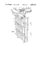
- FIG. 1 is a perspective view of a make-up or ventilation air system for a building constructed in accordance with one embodiment of this invention
- FIG. 2 is a vertical sectional view taken at the line A--A in FIG. 1;
- FIG. 2a is a horizontal sectional view taken at the line B--B in FIG. 2;
- FIG. 3 is a vertical section through a second embodiment of this invention.
- FIG. 3a is a horizontal sectional view taken at the line B--B in FIG. 3;
- FIG. 4 is a vertical sectional view through a third embodiment of this invention.
- FIG. 4a is an enlarged view of a portion of FIG. 4;
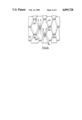
- FIG. 5 is a vertical sectional view taken through a fourth embodiment of this invention.
- FIG. 5a is a horizontal sectional view taken at the line B--B in FIG. 5;
- FIG. 5b is a vertical sectional view, to a larger scale, of one portion of the embodiment shown in FIG. 5;
- FIG. 5c is an elevational view of the same portion as is shown in FIG. 5b;
- FIG. 6 is a vertical sectional view through a further embodiment of this invention utilizing identical overlapping tiles and heated air flow to the air inlet openings;
- FIG. 6a is a vertical sectional view, to a larger scale, of a portion of the embodiment shown in FIG. 6;
- FIG. 6b is an elevational view of the portion shown in FIG. 6a.
- FIG. 6c is an elevational view similar to FIG. 6b, showing an alternative embodiment.
- FIG. 1 shows a partly broken-away perspective view of a system for carrying out the present invention.
- a building wall is shown in part at 10 in the Figure, this being typically a block-and-brick composite structure.
- a steady heat loss is experienced through the wall when the outside temperature is below the inside temperature.
- the wall 10 has an outer surface 12 to which is affixed a mounting plate 14. Secured to the mounting plate 14 are a number of corrugated sub-panels 16', 16", 16'", etc. together constituting the collector panel 16 which is coated on the outside with a solar radiation absorbing material, such as dark paint.
- the panel 16 is composed of a number of overlapping corrugated sub-panels 16', 16", etc. From the top downwardly, they are spaced from the mounting plate 14 at decreasing distances leaving openings 6", 6'" etc. between the sub-panels, which serve as air inlet openings through which the heated outside air enters an air collection space 15.
- the air collection space 15 is defined between and by the collector panels 16 and the mounting plate 14, and in turn communicates with a plenum 22 at the top end of the panel 16.
- the cross-section of the plenum 22 can be made to widen toward a fan housing 30 by adjusting the position of a separator wall 23 such that substantially equal amounts of air are gathered along the length of the plenum 22 from different regions of the air collection space 15.
- the fan housing 30 contains a conventional fan or air impeller 31 and includes motorized dampers 32 which can be adjusted to allow air from the interior of the building to be mixed with heated air coming from the plenum 22.
- a fabric air duct 34 which is preferably flame retardant and made of polyfabric, the duct 34 being suspended by a plurality of duct hangers 36 from a suitably strung support wire or rod 38.
- the air duct has a plurality of openings 40 through which the heated outside air can pass into the building. By appropriately sizing the openings 40, the air can enter the interior of the building as a high velocity air jet, thus promoting good mixing with the air in the building and minimizing stratification.
- the duct 34 be located at the ceiling level for the sake of convenience in industrial and commercial buildings. Other levels and routings for the duct 34 may be chosen in apartment buildings.
- the fan within the housing 30 would typically be sized to meet the ventilation requirements and eliminate any negative pressure in the building.
- a positive pressure can be achieved with outside air entering the building through the fan 31, the air being heated by solar heat, recovered building heat loss, and stratified heat found near a high ceiling. Air can leave the building through cracks and other openings where previously air had entered.
- the plenum 22 overhangs the corrugated panel 16. When the sun stands high in the sky, this arrangement reduces overheating the air.
- the plenum 22 can be provided with a by-pass damper 43 which can be opened when heated air is not required.
- turbulent flow can be prevented, even in windy conditions, if the distance between inlet openings 6', 6" and 6", is chosen to be sufficiently short.
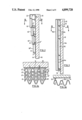
- FIG. 2 is a vertical sectional view of a variant of FIG. 1 at the line A--A and FIG. 2a shows a horizontal sectional view of the structure of FIG. 2 at the line B--B.
- FIG. 2 there is a fourth tier of sub-panels identified by the numeral 6"".
- Both Figures indicate that the openings 6', 6", etc. are placed at the inner portion of each groove 20', 20", etc. by closing off the remainder of the space between overlapping panels, through the insertion of baffles 8 and by positioning the lower plate of plenum 22 so as to leave opening 6'.
- the sub-panel 16"" is open at the bottom as seen at 7 in FIG. 2.
- FIG. 3 is a vertical sectional view, similar to FIG. 2, of another embodiment of the invention.
- a corrugated collector panel 16a is fastened to a wall-mounting plate 14a, at a uniform distance from the bottom to the plenum 22.
- Equal sized inlet holes 6a are provided at the inner portion of the grooves 20 as is more clearly seen in FIG. 3a.
- the latter is a horizontal sectional view of the structure of FIG. 3 taken at line B--B.
- the holes 6a near the panel top are spaced more widely apart than the holes 6a near the bottom of the panel 16.
- the method disclosed permits the construction of collector panels whose surface temperature is the same across the panel. It alternatively permits the construction of panels with increasing or decreasing temperature in any direction or any portion of the panel.
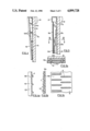
- FIG. 4 shows a vertical sectional view of yet another embodiment of the invention.
- the corrugated panel 116 is spaced at some distance from the wall or the wall mounting plate 114 near the top of the panel, while being closer to the wall at the bottom.
- Identical air inlet opening holes 106 are punched into the panel 116 in the grooves 120 as seen in the enlarged view of the panel 116 in FIG. 4a.
- Suitable support brackets 19a are used where fastening is required.
- the inlet opening holes 106 can be punched on site from the outside. The material of the holes is not punched out, but is rather displaced as shown in FIG. 4a, in order to strengthen the rim 9 of the hole and thus maintain the original strength of the corrugated panel. If the holes, instead of being punched, are produced by a thermal melting method (similar to welding or supersonic heating), the hole material will form a preferred heavy rim framing the hole.
- FIGS. 1 to 4 present facade constructions for ventilation air heating systems which, as embodiments of this invention, are particularly suitable for industrial and commercial buildings.
- the invention is just as attractive for single family dwellings and apartment houses.
- FIGS. 5 and 6 show facade designs which appear particularly acceptable in home building.
- FIG. 5 shows a vertical section through a further embodiment of the invention which consists of a vertical flat panel 16b made of expanded metal sheet with a dark outside house coloring.
- the panel 16b is built up of small sub-panels, each attached to and supported by vertical support-walls 17b as shown in the horizontal sectional view of FIG. 5a, taken at the line B--B in FIG. 5.
- FIGS. 5b and 5c are an enlargement of the panel 16b of FIG. 5, and an elevational view of the panel, respectively.
- the air inlet openings 6b consist of the slits cut into the metal sheet 16b by the conventional metal expanding punch press.
- the flat metal sheet is broken up into a succession of nearly overlapping miniature sub-panels 16b', each row interstitial to the next, creating an attractive image for a house facade.
- the air collection space 15b behind the panel 16b has a cross-section which decreases from the plenum 22 toward the bottom, by virtue of thermal insulation layers 24b increasing in thickness.
- the insulation layers are enclosed in a thin metal film 25b.
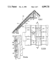
- FIG. 6 is a sectional view of another embodiment of the invention, showing a "porous" solar collector panel acceptable as a facade for domestic housing.
- the panel 216 is made up of a plurality of overlapping small sub-panels 216', 216", etc. shown enlarged in FIG. 6a.
- the two Figures indicate that the construction of the panel is applicable as a roof covering as well as a south-wall facade.
- Rafters 217 and boards 211 serve to support the sub-panels 216', 216", etc.
- the thickness of the individual panel determines the height of the air inlet openings 206.
- the overlap on the sides of the sub-panels limits the width of the openings.
- 6b is an elevational view of the panel 216, and indicates the heated air flow to the air inlet openings 206. From the openings 206, the air flows to the plenum 222 through the air collection channels 215, in part defined by ducting material 225 covering the thermal insulation 224 of the attic room and the rafters 217.
- the sub-panels may be made of a large variety of materials such as ceramic tiles, roofing or siding shingles, metal tiles with a selective coating of desired coloring, glass plates with photovoltaic evaporated films or other types of photovoltaic electric panels etc.
- FIGS. 6-6b show that the inlet airflow provides a very efficient heat transfer from the panels 216 to the air.
- the panels are secured by fastening means 241 which may be used in addition as electrical contacts.
- FIG. 6c shows an alternative tile construction to that illustrated in FIG. 6b.
- the individual tiles are hexagonal and are identified by the numerals 316', 316", etc.
- the air-intake openings are identified with by the numeral 306.
Priority Applications (14)
| Application Number | Priority Date | Filing Date | Title |
|---|---|---|---|
| US07/302,359 US4899728A (en) | 1989-01-27 | 1989-01-27 | Method and apparatus for preheating ventilation air for a building |
| CA000592620A CA1326619C (en) | 1989-01-27 | 1989-03-02 | Method and apparatus for preheating ventilation air for a building |
| US07/444,768 US4934338A (en) | 1989-01-27 | 1989-12-01 | Method and apparatus for preheating ventilation air for a building |
| DE69031540T DE69031540T2 (de) | 1989-01-27 | 1990-01-25 | Vorrichtung zur Vorwärmung von Luft zur Gebäudelüftung |
| ES93104665T ES2106908T3 (es) | 1989-01-27 | 1990-01-25 | Disposicion para precalentar el aire de ventilacion para un edificio. |
| AT93104665T ATE158855T1 (de) | 1989-01-27 | 1990-01-25 | Vorrichtung zur vorwärmung von luft zur gebäudelüftung |
| EP93104665A EP0553893B1 (en) | 1989-01-27 | 1990-01-25 | Arrangement for preheating ventilation air for a building |
| DK90300815.9T DK0380349T3 (da) | 1989-01-27 | 1990-01-25 | Fremgangsmåde og apparat til forvarmning af ventilationsluft til en bygning |
| AT90300815T ATE98010T1 (de) | 1989-01-27 | 1990-01-25 | Nerfahren und vorrichtung zur vorwaermung der luft zur lueftung eines gebaeudes. |
| ES90300815T ES2048964T3 (es) | 1989-01-27 | 1990-01-25 | Metodo y aparato perfeccionados para precalentar aire de ventilacion para edificios. |
| DE69004816T DE69004816T2 (de) | 1989-01-27 | 1990-01-25 | nerfahren und Vorrichtung zur Vorwärmung der Luft zur Lüftung eines Gebäudes. |
| EP90300815A EP0380349B1 (en) | 1989-01-27 | 1990-01-25 | Improved method and apparatus for preheating ventilation air for a building |
| DK93104665.0T DK0553893T3 (da) | 1989-01-27 | 1990-01-25 | Arrangement til forvarmning af ventilationsluft til en bygning |
| HK98100971A HK1001925A1 (en) | 1989-01-27 | 1998-02-09 | Arrangement for preheating ventilation air for a building |
Applications Claiming Priority (1)
| Application Number | Priority Date | Filing Date | Title |
|---|---|---|---|
| US07/302,359 US4899728A (en) | 1989-01-27 | 1989-01-27 | Method and apparatus for preheating ventilation air for a building |
Related Child Applications (1)
| Application Number | Title | Priority Date | Filing Date |
|---|---|---|---|
| US07/444,768 Division US4934338A (en) | 1989-01-27 | 1989-12-01 | Method and apparatus for preheating ventilation air for a building |
Publications (1)
| Publication Number | Publication Date |
|---|---|
| US4899728A true US4899728A (en) | 1990-02-13 |
Family
ID=23167425
Family Applications (2)
| Application Number | Title | Priority Date | Filing Date |
|---|---|---|---|
| US07/302,359 Expired - Lifetime US4899728A (en) | 1989-01-27 | 1989-01-27 | Method and apparatus for preheating ventilation air for a building |
| US07/444,768 Expired - Lifetime US4934338A (en) | 1989-01-27 | 1989-12-01 | Method and apparatus for preheating ventilation air for a building |
Family Applications After (1)
| Application Number | Title | Priority Date | Filing Date |
|---|---|---|---|
| US07/444,768 Expired - Lifetime US4934338A (en) | 1989-01-27 | 1989-12-01 | Method and apparatus for preheating ventilation air for a building |
Country Status (8)
| Country | Link |
|---|---|
| US (2) | US4899728A (da) |
| EP (2) | EP0553893B1 (da) |
| AT (2) | ATE158855T1 (da) |
| CA (1) | CA1326619C (da) |
| DE (2) | DE69031540T2 (da) |
| DK (2) | DK0380349T3 (da) |
| ES (2) | ES2048964T3 (da) |
| HK (1) | HK1001925A1 (da) |
Cited By (31)
| Publication number | Priority date | Publication date | Assignee | Title |
|---|---|---|---|---|
| WO1995020745A1 (de) * | 1994-01-28 | 1995-08-03 | Johann Aschauer | Wärmedämmungs- und wärmekollektoranordnung |
| GB2298705A (en) * | 1995-03-07 | 1996-09-11 | Derek Colin Tolley | Space heating |
| US5692491A (en) * | 1996-04-19 | 1997-12-02 | Midwest Research Institute | Unglazed transpired solar collector having a low thermal-conductance absorber |
| US5931157A (en) * | 1994-01-28 | 1999-08-03 | Aschauer; Johann | Thermal insulation/thermal collector assembly |
| US5935343A (en) * | 1998-03-13 | 1999-08-10 | Hollick; John Carl | Combined solar collector and photovoltaic cells |
| KR20030000938A (ko) * | 2001-06-27 | 2003-01-06 | 한국에너지기술연구원 | 결합 모듈식 무창 기공형 태양열 공기 난방 건축 외장집열판 |
| US20030231826A1 (en) * | 2002-03-21 | 2003-12-18 | Boyd Robert W. | Apparatus with a series of resonator structures situated near an optical waveguide for manipulating optical pulses |
| US20040148933A1 (en) * | 2003-01-30 | 2004-08-05 | Miller Larry D. | Solar-thermal powered generator |
| US6870087B1 (en) | 2001-09-14 | 2005-03-22 | Patrick Gallagher | Assembly method and apparatus for photovoltaic module |
| US6912816B2 (en) | 2001-10-01 | 2005-07-05 | Futura Solar, Llc | Structurally integrated solar collector |
| US20050241633A1 (en) * | 2004-03-24 | 2005-11-03 | Yoursolarhome Inc. | Integrated thermal and photovoltaic solar collector and method for operation and mounting an array of solar collectors |
| EP1596138A2 (en) * | 2004-05-14 | 2005-11-16 | John C. Hollick | Method and apparatus for preheating ventilation air for a building |
| US20060130827A1 (en) * | 2004-12-22 | 2006-06-22 | Bayer Materialscience Ag | Solar thermal collector |
| US20070277811A1 (en) * | 2006-05-18 | 2007-12-06 | Hollick John C | Method and apparatus for cooling ventilation air for a building |
| US20070284077A1 (en) * | 2006-05-29 | 2007-12-13 | Matteo B. Gravina | Smart Solar Roof |
| US20080139106A1 (en) * | 2006-12-12 | 2008-06-12 | Vachon Christian | Roof-mounted ventilation air duct |
| WO2008095502A2 (en) * | 2007-02-05 | 2008-08-14 | Paul Riis Arndt | Solar air heater for heating air flow |
| US20080271399A1 (en) * | 2007-05-01 | 2008-11-06 | James Carolan | Panel |
| US7481057B2 (en) * | 2002-04-01 | 2009-01-27 | Niket Keshav Patwardhan | Low cost solar energy extraction |
| FR2929379A1 (fr) * | 2008-04-01 | 2009-10-02 | Opaly Soc Par Actions Simplifi | Panneau creux de bardage exterieur pour batiment. |
| US20100000520A1 (en) * | 2007-07-26 | 2010-01-07 | Vachon Christian | Perforated transparent glazing for heat recovery and solar air heating |
| US7677243B2 (en) | 2007-01-22 | 2010-03-16 | Wal-Mart Stores, Inc. | Solar heating system and architectural structure with a solar heating system |
| WO2009125159A3 (fr) * | 2008-04-01 | 2010-08-19 | OPALY, Société par actions simplifiée | Procede et dispositif d'habillage de façade ou de couverture de batiment |
| US20110120449A1 (en) * | 2008-07-29 | 2011-05-26 | Ryan Thomas D | Curved Transpired Solar Air Heater and Conduit |
| US20110214364A1 (en) * | 2010-03-04 | 2011-09-08 | Michael Fuller Architects, Pc | Building with integrated natural systems |
| EP2620713A2 (en) | 2012-01-30 | 2013-07-31 | Hollick Solar Systems Limited | Method and apparatus for two stage cooling of ambient air |
| NL2011550C2 (nl) * | 2013-10-03 | 2015-04-07 | Unda Maris Holding N V | Wandsysteem, gevelpaneel daarvoor, en daarmee voorzien gebouw. |
| EP3002454A1 (en) | 2014-10-02 | 2016-04-06 | Hollick Solar Systems Limited | Transpired solar collector chimney tower |
| WO2017009638A1 (en) * | 2015-07-15 | 2017-01-19 | Energy Transitions Limited | Transpired solar collector |
| US9574783B2 (en) | 2006-05-18 | 2017-02-21 | Hollick Solar Systems Limited | Method and apparatus for two stage cooling of ambient air |
| WO2017076773A1 (en) | 2015-11-06 | 2017-05-11 | Tata Steel Ijmuiden B.V. | Transpired solar collector |
Families Citing this family (14)
| Publication number | Priority date | Publication date | Assignee | Title |
|---|---|---|---|---|
| US5186160A (en) * | 1991-08-28 | 1993-02-16 | Klein Ii Richard J | Solar radon reduction |
| CA2230471C (en) * | 1998-02-25 | 2001-09-11 | John Carl Hollick | Combined solar collector and photovoltaic cells |
| US20050103327A1 (en) * | 2003-11-18 | 2005-05-19 | Atomic Energy Council - Institute Of Nuclear Energy Research | Passive energy saving system for a building |
| JP4991849B2 (ja) * | 2006-05-25 | 2012-08-01 | カオ,シュリアン | 大きいサイズの中空セラミック板の製造方法及び応用製品 |
| CN101294747B (zh) * | 2007-04-25 | 2010-05-26 | 富准精密工业(深圳)有限公司 | 自然空调装置 |
| CN101311644B (zh) * | 2007-05-25 | 2010-09-29 | 富准精密工业(深圳)有限公司 | 自然空调装置 |
| CN101319820B (zh) * | 2007-06-08 | 2010-12-22 | 富准精密工业(深圳)有限公司 | 自然空调装置 |
| CN101418974B (zh) * | 2007-10-26 | 2011-10-12 | 富准精密工业(深圳)有限公司 | 自然空调装置 |
| CN101469898B (zh) * | 2007-12-29 | 2010-06-16 | 富准精密工业(深圳)有限公司 | 自然空调装置 |
| WO2010086126A1 (en) | 2009-01-29 | 2010-08-05 | Corus Uk Limited | Heating apparatus using solar energy and method of heating using solar energy |
| DE202010001134U1 (de) | 2010-01-20 | 2010-06-24 | Moser, Peter | Kombination aus fassadenmontierten Solar-Luft-Kollektor mit integrierter Luft-Wärmepumpe |
| EP2553739A2 (en) | 2010-03-30 | 2013-02-06 | Tata Steel UK Limited | Arrangement for generating electricity with thermoelectric generators and solar energy collector means |
| CN102141304A (zh) * | 2011-03-10 | 2011-08-03 | 同济大学 | 一种高效气水复合型太阳能集热装置及其应用 |
| US8850752B1 (en) * | 2013-01-14 | 2014-10-07 | Timothy Michael Graboski | Hybrid sealed attic insulation and ventilation system |
Citations (4)
| Publication number | Priority date | Publication date | Assignee | Title |
|---|---|---|---|---|
| US4126270A (en) * | 1976-01-23 | 1978-11-21 | Hummel Richard L | Solar energy collection system |
| US4471761A (en) * | 1982-03-26 | 1984-09-18 | Purdue Research Foundation | Louvered air-heating solar collector |
| CA1196825A (en) * | 1982-05-04 | 1985-11-19 | John C. Hollick | Method for preheating ventilation air in a building |
| US4774932A (en) * | 1988-02-11 | 1988-10-04 | Hollick John C | Method and apparatus for preheating ventilation air for a building |
Family Cites Families (14)
| Publication number | Priority date | Publication date | Assignee | Title |
|---|---|---|---|---|
| US3412728A (en) * | 1965-10-22 | 1968-11-26 | Harry E. Thomason | Solar heating equipment |
| US4122675A (en) * | 1977-03-17 | 1978-10-31 | Jack Polyak | Solar heat supplemented convection air stack with turbine blades |
| FR2443030A1 (fr) * | 1978-08-16 | 1980-06-27 | Bertin & Cie | Capteur d'energie solaire |
| DE2917098A1 (de) * | 1979-04-27 | 1980-11-06 | Max Planck Gesellschaft | Waermekollektor |
| DE2929219A1 (de) | 1979-07-19 | 1981-02-05 | Wieneke Franz | Solardach absorber |
| FR2469674A1 (fr) * | 1979-11-15 | 1981-05-22 | Omnium Fs Indl Cal | Capteurs d'energie solaire comprenant un absorbeur en materiau cellulosique bitumine et profile |
| GB2073872B (en) * | 1980-01-24 | 1983-10-19 | Limbrey J C S | Fluid permeable sheet |
| DE3006905A1 (de) * | 1980-02-23 | 1981-09-03 | Max-Planck-Gesellschaft zur Förderung der Wissenschaften e.V., 3400 Göttingen | Energieabsorberanlage |
| DE3014445A1 (de) * | 1980-04-15 | 1981-10-22 | SES Friedrich Müller GmbH, 8045 Ismaning | Energiedach zur nutzung von sonnen und umgebungswaerme |
| DE3314637A1 (de) * | 1982-04-27 | 1983-11-17 | BM CHEMIE Kunststoff GmbH, 5678 Wermelskirchen | Dachstein |
| US4471758A (en) * | 1982-08-13 | 1984-09-18 | Jennings Donald E | House siding solar panel |
| FR2537258A1 (fr) * | 1982-12-03 | 1984-06-08 | Hay Georges | Capteurs solaires a effet de serre et soutirage d'air realises a partir de modules ou elements standards integres aux constituants des batiments |
| DE3334052A1 (de) * | 1983-09-21 | 1985-04-18 | August 7000 Stuttgart Ridder | Fassadenverkleidung aus profiliertem blech fuer gebaeude |
| JP5340532B2 (ja) * | 2006-10-30 | 2013-11-13 | 株式会社須山歯研 | イヤモ−ルドの製法及びそのイヤモ−ルド |
-
1989
- 1989-01-27 US US07/302,359 patent/US4899728A/en not_active Expired - Lifetime
- 1989-03-02 CA CA000592620A patent/CA1326619C/en not_active Expired - Lifetime
- 1989-12-01 US US07/444,768 patent/US4934338A/en not_active Expired - Lifetime
-
1990
- 1990-01-25 AT AT93104665T patent/ATE158855T1/de not_active IP Right Cessation
- 1990-01-25 AT AT90300815T patent/ATE98010T1/de not_active IP Right Cessation
- 1990-01-25 ES ES90300815T patent/ES2048964T3/es not_active Expired - Lifetime
- 1990-01-25 DE DE69031540T patent/DE69031540T2/de not_active Expired - Lifetime
- 1990-01-25 EP EP93104665A patent/EP0553893B1/en not_active Expired - Lifetime
- 1990-01-25 DK DK90300815.9T patent/DK0380349T3/da active
- 1990-01-25 DK DK93104665.0T patent/DK0553893T3/da active
- 1990-01-25 EP EP90300815A patent/EP0380349B1/en not_active Expired - Lifetime
- 1990-01-25 ES ES93104665T patent/ES2106908T3/es not_active Expired - Lifetime
- 1990-01-25 DE DE69004816T patent/DE69004816T2/de not_active Expired - Lifetime
-
1998
- 1998-02-09 HK HK98100971A patent/HK1001925A1/xx not_active IP Right Cessation
Patent Citations (4)
| Publication number | Priority date | Publication date | Assignee | Title |
|---|---|---|---|---|
| US4126270A (en) * | 1976-01-23 | 1978-11-21 | Hummel Richard L | Solar energy collection system |
| US4471761A (en) * | 1982-03-26 | 1984-09-18 | Purdue Research Foundation | Louvered air-heating solar collector |
| CA1196825A (en) * | 1982-05-04 | 1985-11-19 | John C. Hollick | Method for preheating ventilation air in a building |
| US4774932A (en) * | 1988-02-11 | 1988-10-04 | Hollick John C | Method and apparatus for preheating ventilation air for a building |
Non-Patent Citations (1)
| Title |
|---|
| PCT International Application, Mar. 20, 1980; Inventors, Grossin et al, 24 pages. * |
Cited By (54)
| Publication number | Priority date | Publication date | Assignee | Title |
|---|---|---|---|---|
| WO1995020745A1 (de) * | 1994-01-28 | 1995-08-03 | Johann Aschauer | Wärmedämmungs- und wärmekollektoranordnung |
| US5931157A (en) * | 1994-01-28 | 1999-08-03 | Aschauer; Johann | Thermal insulation/thermal collector assembly |
| GB2298705A (en) * | 1995-03-07 | 1996-09-11 | Derek Colin Tolley | Space heating |
| GB2298705B (en) * | 1995-03-07 | 1998-09-16 | Derek Colin Tolley | Space Heating |
| US5692491A (en) * | 1996-04-19 | 1997-12-02 | Midwest Research Institute | Unglazed transpired solar collector having a low thermal-conductance absorber |
| US5935343A (en) * | 1998-03-13 | 1999-08-10 | Hollick; John Carl | Combined solar collector and photovoltaic cells |
| KR20030000938A (ko) * | 2001-06-27 | 2003-01-06 | 한국에너지기술연구원 | 결합 모듈식 무창 기공형 태양열 공기 난방 건축 외장집열판 |
| US6870087B1 (en) | 2001-09-14 | 2005-03-22 | Patrick Gallagher | Assembly method and apparatus for photovoltaic module |
| US6912816B2 (en) | 2001-10-01 | 2005-07-05 | Futura Solar, Llc | Structurally integrated solar collector |
| US20030231826A1 (en) * | 2002-03-21 | 2003-12-18 | Boyd Robert W. | Apparatus with a series of resonator structures situated near an optical waveguide for manipulating optical pulses |
| US7481057B2 (en) * | 2002-04-01 | 2009-01-27 | Niket Keshav Patwardhan | Low cost solar energy extraction |
| US20040148933A1 (en) * | 2003-01-30 | 2004-08-05 | Miller Larry D. | Solar-thermal powered generator |
| US7340898B2 (en) * | 2003-01-30 | 2008-03-11 | Miller Larry D | Solar-thermal powered generator |
| US7896000B2 (en) | 2004-03-24 | 2011-03-01 | Yoursolarhome Inc. | Integrated thermal and photovoltaic solar collector and method for operation and mounting an array of solar collectors |
| US20050241633A1 (en) * | 2004-03-24 | 2005-11-03 | Yoursolarhome Inc. | Integrated thermal and photovoltaic solar collector and method for operation and mounting an array of solar collectors |
| US20090133690A1 (en) * | 2004-03-24 | 2009-05-28 | Yoursolarhome Inc. | Integrated thermal and photovoltaic solar collector and method for operation and mounting an array of solar collectors |
| US7484507B2 (en) | 2004-03-24 | 2009-02-03 | Yoursolarhome Inc. | Method and apparatus for mounting an array of solar collectors |
| US20050252507A1 (en) * | 2004-05-14 | 2005-11-17 | John Hollick | Method and apparatus for preheating ventilation air for a building |
| EP1596138A3 (en) * | 2004-05-14 | 2007-05-23 | John C. Hollick | Method and apparatus for preheating ventilation air for a building |
| US7032588B2 (en) | 2004-05-14 | 2006-04-25 | John Hollick | Method and apparatus for preheating ventilation air for a building |
| JP4676808B2 (ja) * | 2004-05-14 | 2011-04-27 | ジョン・ホリック | 建物用の換気空気を予め加熱するための方法及び装置 |
| JP2005326142A (ja) * | 2004-05-14 | 2005-11-24 | John Hollick | 建物用の換気空気を予め加熱するための方法及び装置 |
| EP1596138A2 (en) * | 2004-05-14 | 2005-11-16 | John C. Hollick | Method and apparatus for preheating ventilation air for a building |
| US20060130827A1 (en) * | 2004-12-22 | 2006-06-22 | Bayer Materialscience Ag | Solar thermal collector |
| US9574783B2 (en) | 2006-05-18 | 2017-02-21 | Hollick Solar Systems Limited | Method and apparatus for two stage cooling of ambient air |
| US20070277811A1 (en) * | 2006-05-18 | 2007-12-06 | Hollick John C | Method and apparatus for cooling ventilation air for a building |
| US8827779B2 (en) * | 2006-05-18 | 2014-09-09 | Hollick Solar Systems Limited | Method and apparatus for cooling ventilation air for a building |
| US20070284077A1 (en) * | 2006-05-29 | 2007-12-13 | Matteo B. Gravina | Smart Solar Roof |
| US20080139106A1 (en) * | 2006-12-12 | 2008-06-12 | Vachon Christian | Roof-mounted ventilation air duct |
| US7677243B2 (en) | 2007-01-22 | 2010-03-16 | Wal-Mart Stores, Inc. | Solar heating system and architectural structure with a solar heating system |
| WO2008095502A2 (en) * | 2007-02-05 | 2008-08-14 | Paul Riis Arndt | Solar air heater for heating air flow |
| US20100186734A1 (en) * | 2007-02-05 | 2010-07-29 | Paul Riis Arndt | Solar air heater for heating air flow |
| WO2008095502A3 (en) * | 2007-02-05 | 2009-05-14 | Paul Riis Arndt | Solar air heater for heating air flow |
| US8172972B2 (en) | 2007-05-01 | 2012-05-08 | Kingspan Research And Developments Limited | Panel |
| US8028483B2 (en) | 2007-05-01 | 2011-10-04 | Kingspan Research And Developments Limited | Panel |
| US20080271399A1 (en) * | 2007-05-01 | 2008-11-06 | James Carolan | Panel |
| US20100000520A1 (en) * | 2007-07-26 | 2010-01-07 | Vachon Christian | Perforated transparent glazing for heat recovery and solar air heating |
| FR2929379A1 (fr) * | 2008-04-01 | 2009-10-02 | Opaly Soc Par Actions Simplifi | Panneau creux de bardage exterieur pour batiment. |
| US20110036539A1 (en) * | 2008-04-01 | 2011-02-17 | Opaly | Method and device for trimming for facade or roof of a building |
| WO2009125159A3 (fr) * | 2008-04-01 | 2010-08-19 | OPALY, Société par actions simplifiée | Procede et dispositif d'habillage de façade ou de couverture de batiment |
| US20110120449A1 (en) * | 2008-07-29 | 2011-05-26 | Ryan Thomas D | Curved Transpired Solar Air Heater and Conduit |
| US9206997B2 (en) | 2008-07-29 | 2015-12-08 | Syenergy Integrated Energy Solutions Inc. | Curved transpired solar air heater and conduit |
| US20110214364A1 (en) * | 2010-03-04 | 2011-09-08 | Michael Fuller Architects, Pc | Building with integrated natural systems |
| US8371073B2 (en) | 2010-03-04 | 2013-02-12 | Michael Fuller Architects, Pc | Building with integrated natural systems |
| EP2620713A3 (en) * | 2012-01-30 | 2013-08-07 | Hollick Solar Systems Limited | Method and apparatus for two stage cooling of ambient air |
| EP2620713A2 (en) | 2012-01-30 | 2013-07-31 | Hollick Solar Systems Limited | Method and apparatus for two stage cooling of ambient air |
| NL2011550C2 (nl) * | 2013-10-03 | 2015-04-07 | Unda Maris Holding N V | Wandsysteem, gevelpaneel daarvoor, en daarmee voorzien gebouw. |
| EP3002454A1 (en) | 2014-10-02 | 2016-04-06 | Hollick Solar Systems Limited | Transpired solar collector chimney tower |
| WO2017009638A1 (en) * | 2015-07-15 | 2017-01-19 | Energy Transitions Limited | Transpired solar collector |
| CN107850343A (zh) * | 2015-07-15 | 2018-03-27 | 能源转换有限公司 | 穿透式太阳能集热器 |
| US20180209665A1 (en) * | 2015-07-15 | 2018-07-26 | Energy Transitions Limited | Transpired Solar Collector |
| JP2018528385A (ja) * | 2015-07-15 | 2018-09-27 | エナジー トランジションズ リミテッドEnergy Transitions Limited | 蒸散型太陽光収集器、及び、蒸散型太陽光収集器を製造する方法 |
| RU2749242C2 (ru) * | 2015-07-15 | 2021-06-07 | Энерджи Транзишнс Лимитед | Солнечный коллектор транспирационного типа |
| WO2017076773A1 (en) | 2015-11-06 | 2017-05-11 | Tata Steel Ijmuiden B.V. | Transpired solar collector |
Also Published As
| Publication number | Publication date |
|---|---|
| EP0553893A2 (en) | 1993-08-04 |
| DK0553893T3 (da) | 1997-12-22 |
| ATE98010T1 (de) | 1993-12-15 |
| DE69031540T2 (de) | 1998-01-29 |
| DK0380349T3 (da) | 1994-03-28 |
| US4934338A (en) | 1990-06-19 |
| DE69004816T2 (de) | 1994-05-26 |
| ATE158855T1 (de) | 1997-10-15 |
| EP0553893B1 (en) | 1997-10-01 |
| EP0553893A3 (en) | 1993-10-27 |
| DE69031540D1 (de) | 1997-11-06 |
| HK1001925A1 (en) | 1998-07-17 |
| DE69004816D1 (de) | 1994-01-13 |
| ES2048964T3 (es) | 1994-04-01 |
| EP0380349A1 (en) | 1990-08-01 |
| ES2106908T3 (es) | 1997-11-16 |
| EP0380349B1 (en) | 1993-12-01 |
| CA1326619C (en) | 1994-02-01 |
Similar Documents
| Publication | Publication Date | Title |
|---|---|---|
| US4899728A (en) | Method and apparatus for preheating ventilation air for a building | |
| EP1596138B1 (en) | Method and apparatus for preheating ventilation air for a building | |
| EP2021701B1 (en) | Method and apparatus for cooling ventilation air for a building | |
| US4323054A (en) | Solar energy collection system | |
| US4774932A (en) | Method and apparatus for preheating ventilation air for a building | |
| US8276580B2 (en) | Modular transpired solar air collector | |
| US4557253A (en) | Solar collector employing conventional siding, and air distribution system therefor | |
| US9574783B2 (en) | Method and apparatus for two stage cooling of ambient air | |
| CA1178105A (en) | Stack draft stabilizing device | |
| CA1196825A (en) | Method for preheating ventilation air in a building | |
| JP2846913B2 (ja) | ビルの空気予熱方法および装置 | |
| CN220355509U (zh) | 一种外墙通风立面装置 | |
| JP4541372B2 (ja) | 空気式太陽集熱換気システム | |
| JPS5911818B2 (ja) | 太陽壁の改良 | |
| CA1151038A (en) | Solar energy heating system | |
| JPH0719522A (ja) | 建物の通気装置 | |
| JPS61289241A (ja) | 風防装置 |
Legal Events
| Date | Code | Title | Description |
|---|---|---|---|
| AS | Assignment |
Owner name: SOLARWALL INTERNATIONAL LIMITED, CHANNEL ISLANDS Free format text: ASSIGNMENT OF ASSIGNORS INTEREST.;ASSIGNORS:PETER, ROLF W.;HOLLICK, JOHN C.;REEL/FRAME:005035/0304 Effective date: 19881221 |
|
| STCF | Information on status: patent grant |
Free format text: PATENTED CASE |
|
| FEPP | Fee payment procedure |
Free format text: PAYOR NUMBER ASSIGNED (ORIGINAL EVENT CODE: ASPN); ENTITY STATUS OF PATENT OWNER: SMALL ENTITY |
|
| FPAY | Fee payment |
Year of fee payment: 4 |
|
| FPAY | Fee payment |
Year of fee payment: 8 |
|
| SULP | Surcharge for late payment | ||
| REMI | Maintenance fee reminder mailed | ||
| FPAY | Fee payment |
Year of fee payment: 12 |