US4899261A - Automobile headlamp with small height and high flux recovery - Google Patents
Automobile headlamp with small height and high flux recovery Download PDFInfo
- Publication number
- US4899261A US4899261A US07/257,211 US25721188A US4899261A US 4899261 A US4899261 A US 4899261A US 25721188 A US25721188 A US 25721188A US 4899261 A US4899261 A US 4899261A
- Authority
- US
- United States
- Prior art keywords
- reflector
- light source
- vertical
- headlamp
- optical axis
- Prior art date
- Legal status (The legal status is an assumption and is not a legal conclusion. Google has not performed a legal analysis and makes no representation as to the accuracy of the status listed.)
- Expired - Fee Related
Links
- 230000004907 flux Effects 0.000 title abstract description 12
- 238000011084 recovery Methods 0.000 title description 11
- 239000011521 glass Substances 0.000 claims abstract description 11
- 230000003287 optical effect Effects 0.000 claims description 36
- 230000015572 biosynthetic process Effects 0.000 claims description 7
- 238000004519 manufacturing process Methods 0.000 abstract description 2
- 238000000465 moulding Methods 0.000 description 3
- 230000002035 prolonged effect Effects 0.000 description 3
- 230000000644 propagated effect Effects 0.000 description 3
- 230000008901 benefit Effects 0.000 description 2
- 238000005304 joining Methods 0.000 description 2
- 230000007704 transition Effects 0.000 description 2
- 206010040925 Skin striae Diseases 0.000 description 1
- 238000004026 adhesive bonding Methods 0.000 description 1
- 230000001174 ascending effect Effects 0.000 description 1
- 238000012512 characterization method Methods 0.000 description 1
- 238000009826 distribution Methods 0.000 description 1
- 230000006872 improvement Effects 0.000 description 1
- 239000000463 material Substances 0.000 description 1
- 230000004048 modification Effects 0.000 description 1
- 238000012986 modification Methods 0.000 description 1
- 229920003023 plastic Polymers 0.000 description 1
- 239000004033 plastic Substances 0.000 description 1
- 239000007787 solid Substances 0.000 description 1
- 230000007480 spreading Effects 0.000 description 1
- 238000003892 spreading Methods 0.000 description 1
- 230000000007 visual effect Effects 0.000 description 1
Images


Classifications
-
- F—MECHANICAL ENGINEERING; LIGHTING; HEATING; WEAPONS; BLASTING
- F21—LIGHTING
- F21S—NON-PORTABLE LIGHTING DEVICES; SYSTEMS THEREOF; VEHICLE LIGHTING DEVICES SPECIALLY ADAPTED FOR VEHICLE EXTERIORS
- F21S41/00—Illuminating devices specially adapted for vehicle exteriors, e.g. headlamps
- F21S41/10—Illuminating devices specially adapted for vehicle exteriors, e.g. headlamps characterised by the light source
- F21S41/14—Illuminating devices specially adapted for vehicle exteriors, e.g. headlamps characterised by the light source characterised by the type of light source
-
- F—MECHANICAL ENGINEERING; LIGHTING; HEATING; WEAPONS; BLASTING
- F21—LIGHTING
- F21S—NON-PORTABLE LIGHTING DEVICES; SYSTEMS THEREOF; VEHICLE LIGHTING DEVICES SPECIALLY ADAPTED FOR VEHICLE EXTERIORS
- F21S41/00—Illuminating devices specially adapted for vehicle exteriors, e.g. headlamps
-
- F—MECHANICAL ENGINEERING; LIGHTING; HEATING; WEAPONS; BLASTING
- F21—LIGHTING
- F21S—NON-PORTABLE LIGHTING DEVICES; SYSTEMS THEREOF; VEHICLE LIGHTING DEVICES SPECIALLY ADAPTED FOR VEHICLE EXTERIORS
- F21S41/00—Illuminating devices specially adapted for vehicle exteriors, e.g. headlamps
- F21S41/10—Illuminating devices specially adapted for vehicle exteriors, e.g. headlamps characterised by the light source
- F21S41/14—Illuminating devices specially adapted for vehicle exteriors, e.g. headlamps characterised by the light source characterised by the type of light source
- F21S41/162—Incandescent light sources, e.g. filament or halogen lamps
-
- F—MECHANICAL ENGINEERING; LIGHTING; HEATING; WEAPONS; BLASTING
- F21—LIGHTING
- F21S—NON-PORTABLE LIGHTING DEVICES; SYSTEMS THEREOF; VEHICLE LIGHTING DEVICES SPECIALLY ADAPTED FOR VEHICLE EXTERIORS
- F21S41/00—Illuminating devices specially adapted for vehicle exteriors, e.g. headlamps
- F21S41/20—Illuminating devices specially adapted for vehicle exteriors, e.g. headlamps characterised by refractors, transparent cover plates, light guides or filters
- F21S41/28—Cover glass
-
- F—MECHANICAL ENGINEERING; LIGHTING; HEATING; WEAPONS; BLASTING
- F21—LIGHTING
- F21S—NON-PORTABLE LIGHTING DEVICES; SYSTEMS THEREOF; VEHICLE LIGHTING DEVICES SPECIALLY ADAPTED FOR VEHICLE EXTERIORS
- F21S41/00—Illuminating devices specially adapted for vehicle exteriors, e.g. headlamps
- F21S41/20—Illuminating devices specially adapted for vehicle exteriors, e.g. headlamps characterised by refractors, transparent cover plates, light guides or filters
- F21S41/285—Refractors, transparent cover plates, light guides or filters not provided in groups F21S41/24 - F21S41/2805
-
- F—MECHANICAL ENGINEERING; LIGHTING; HEATING; WEAPONS; BLASTING
- F21—LIGHTING
- F21S—NON-PORTABLE LIGHTING DEVICES; SYSTEMS THEREOF; VEHICLE LIGHTING DEVICES SPECIALLY ADAPTED FOR VEHICLE EXTERIORS
- F21S41/00—Illuminating devices specially adapted for vehicle exteriors, e.g. headlamps
- F21S41/30—Illuminating devices specially adapted for vehicle exteriors, e.g. headlamps characterised by reflectors
- F21S41/32—Optical layout thereof
- F21S41/321—Optical layout thereof the reflector being a surface of revolution or a planar surface, e.g. truncated
-
- F—MECHANICAL ENGINEERING; LIGHTING; HEATING; WEAPONS; BLASTING
- F21—LIGHTING
- F21S—NON-PORTABLE LIGHTING DEVICES; SYSTEMS THEREOF; VEHICLE LIGHTING DEVICES SPECIALLY ADAPTED FOR VEHICLE EXTERIORS
- F21S41/00—Illuminating devices specially adapted for vehicle exteriors, e.g. headlamps
- F21S41/30—Illuminating devices specially adapted for vehicle exteriors, e.g. headlamps characterised by reflectors
- F21S41/32—Optical layout thereof
- F21S41/323—Optical layout thereof the reflector having two perpendicular cross sections having regular geometrical curves of a distinct nature
-
- F—MECHANICAL ENGINEERING; LIGHTING; HEATING; WEAPONS; BLASTING
- F21—LIGHTING
- F21S—NON-PORTABLE LIGHTING DEVICES; SYSTEMS THEREOF; VEHICLE LIGHTING DEVICES SPECIALLY ADAPTED FOR VEHICLE EXTERIORS
- F21S41/00—Illuminating devices specially adapted for vehicle exteriors, e.g. headlamps
- F21S41/30—Illuminating devices specially adapted for vehicle exteriors, e.g. headlamps characterised by reflectors
- F21S41/32—Optical layout thereof
- F21S41/33—Multi-surface reflectors, e.g. reflectors with facets or reflectors with portions of different curvature
- F21S41/331—Multi-surface reflectors, e.g. reflectors with facets or reflectors with portions of different curvature the reflector consisting of complete annular areas
- F21S41/333—Multi-surface reflectors, e.g. reflectors with facets or reflectors with portions of different curvature the reflector consisting of complete annular areas with discontinuity at the junction between adjacent areas
-
- F—MECHANICAL ENGINEERING; LIGHTING; HEATING; WEAPONS; BLASTING
- F21—LIGHTING
- F21S—NON-PORTABLE LIGHTING DEVICES; SYSTEMS THEREOF; VEHICLE LIGHTING DEVICES SPECIALLY ADAPTED FOR VEHICLE EXTERIORS
- F21S41/00—Illuminating devices specially adapted for vehicle exteriors, e.g. headlamps
- F21S41/30—Illuminating devices specially adapted for vehicle exteriors, e.g. headlamps characterised by reflectors
- F21S41/32—Optical layout thereof
- F21S41/33—Multi-surface reflectors, e.g. reflectors with facets or reflectors with portions of different curvature
- F21S41/334—Multi-surface reflectors, e.g. reflectors with facets or reflectors with portions of different curvature the reflector consisting of patch like sectors
- F21S41/336—Multi-surface reflectors, e.g. reflectors with facets or reflectors with portions of different curvature the reflector consisting of patch like sectors with discontinuity at the junction between adjacent areas
Definitions
- the present invention relates generally to headlamps for automobile vehicles, and concerns in particular a headlamp having a small height, which enables a good recovery of the light flux emitted by the lamp, and which forms behind the lens a distribution of light which is particularly well adapted to the desired illuminating function.
- a well known solution to this problem consists of using a headlamp which is conventional in optical design and comprises a lamp the filament (or other light source) of which is focussed in a parabolic reflector, and to truncate the reflector with two flat upper and lower reflecting surfaces.
- Another object of the invention is to give the images of the filament formed by the reflector an orientation which is particularly adapted to the formation of a road beam.
- the visual comfort of a road beam is given, on the one hand, by a point of concentration on the axis of the road (that is to say the optical axis of the lamp) and, on the other hand, by a large width and small depth of the beam.
- a further object of the invention is to provide that a large proportion of the images of the filament participating in the formation of the beam are horizontal or slightly inclined.
- a headlamp for an automobile vehicle of the kind comprising a light, a reflector defining an optical axis and a closing glass
- the reflector comprises a base part substantially in the form of a paraboloid of revolution focussed on the source, and side pieces in the form of parabolic cylinders having a vertical generatrix; and deflecting means extending near the source substantially over the full height of the lamp and adapted to deflect the direction of the light rays coming from the source in order to re-emit them in an essentially horizontal direction towards the said side pieces of the reflector, which reflect them in a direction essentially parallel to the optical axis so that they participate in the formation of the beam.
- the light source is an elongated filament orientated in line with the optical axis.
- the base part of the reflector extends forwards as far as the vertical plane perpendicular to the optical axis and passing through the light source.
- the deflecting means in projection in a horizontal plane, occupy on both sides of the optical axis an angular interval, relative to the light source, substantially equal to the angular interval occupied by the side pieces of the reflector, and the rays re-emitted by the side pieces of the reflector are contained in the respective vertical planes containing the incident rays.
- the deflecting means may comprise two toroidal lens elements centered on the light source and extending over the full height of the lamp, and each constituted by a succession of staged deflecting prisms.
- the deflecting means may comprise two toroidal lens elements centered on the light source and occupying an intermediate part of the height of the lamp, and constituted by a succession of staged deflecting prisms; and two pairs of auxiliary reflectors in the form of toroidal paraboloids having a vertical axis of rotation passing through the source and occupying, respectively above and below the toroidal lens elements, the remainder of the height of the lamp.
- the side pieces of the reflector are parts of a parabolic cylinder with a vertical generatrix, having a vertical line passing through the light source as the focal line and the toroidal lens elements and the two pairs of auxiliary reflectors each occupy a third of the height of the lamp.
- the deflecting means comprise a toroidal lens element centered on the light source, extending over about 180° and in front of the latter, and occupying an intermediate part of the height of the reflector, the said element being constituted by a succession of staged deflecting prisms; and two pairs of auxiliary reflectors in the form of parabolic cylinders having a horizontal generatrix parallel to the optical axis, having the same focal line coincident with the said optical axis, and occupying, respectively above and below the toroidal lens element, the remainder of the height of the lamp, and the side pieces of the reflector comprise at the level of the said toroidal lens element, two parts of parabolic cylinder having a vertical generatrix, having a vertical line passing through the light source as the focal line, and above and below the said two parts, and at the level of the two pairs of auxiliary reflectors respectively, parts of two parabolic cylinders having a vertical generatrix, having respectively for focal
- FIG. 1 is a view in horizontal section of a lamp according to a first embodiment of the invention
- FIG. 2 is a front view of the lamp in FIG. 1, without its glass lens;
- FIG. 3 is a view in vertical axial section of the lamp in FIGS. 1 and 2;
- FIG. 4 is a partial perspective view of the lamp in FIGS. 1 to 3;
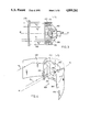
- FIG. 5 is a view in horizontal section of a second embodiment of lamp;
- FIG. 6 is a front view of the lamp in FIG. 5, without its glass lens;
- FIG. 7 is a view in vertical axial section of the lamp in FIGS. 5 and 6;
- FIG. 8 is a partial perspective view of the lamp in FIGS. 5 to 7;
- FIG. 9 is a view from above of a third embodiment of lamp.
- FIG. 10 is a front view of the lamp in FIG. 5, without its glass lens;
- FIG. 11 is a view in vertical axial section of the lamp in FIGS. 9 and 10;
- FIG. 12 is a partial perspective view of the lamp in FIGS. 9 to 11;
- FIG. 13 shows, in a projected plane perpendicular to the optical axis, the position of a certain number of images of the filament, without the glass lens, produced by a part of the lamp in FIGS. 9 to 12;
- FIG. 14 is an alternative embodiment of a part of a lamp in accordance with the present invention.
- a headlamp conforming to a first embodiment of the present invention comprises a lamp 100, a complex reflector, indicated in total by 200, deflecting means 300 acting by refraction, and also a front closing glass 400.
- the lamp 100 is provided with a filament 102 which will be considered to be cylindrical as a first approximation, disposed axially on the optical axis x--x of the lamp.
- the reflector 200 comprises, first of all, a base part 210 which is in the form of a paraboloid of revolution, the focus of which F 1 is situated approximately at the center of the filament 102 on the axis x--x.
- the ratio between its focal distance and the total height of the reflector is of the order of 1:4, for the purposes described hereinafter.
- the reflector 210 extends forwards as far as the vertical plane perpendicular to the optical axis x--x passing through the centre of the filament 102, as indicated by the lateral lines shown in FIG. 2 in the form or arcs of a circle centered on the filament.
- the base part 210 of the reflector is, on the other hand, prolonged towards the front, being delimited above and below by the two horizontal planes between which the lamp is contained. These prolongations are indicated by 212. In this way the reflector 210 covers more than the entire field of light emitted towards the rear by the filament 102.
- the reflector also comprises two side pieces 222, 224 which cooperate with the deflecting means 300. More precisely, the deflecting means are constituted by two toroidal Fresnel lens elements having vertical axes, 302 and 304 respectively, focussed on the center of the filament 102 and comprising on their inner surfaces deflecting prisms staged in succession and contained in respective horizontal planes. The deflecting prisms can alternatively be formed on the outer surfaces of the lenses 302, 304.
- a "toroidal" volume or surface means a volume or surface engendered by the rotation of a planar circumference and, by extension, of any planar curve, about an axis contained in the plane of the circumference or of the curve.
- the two corresponding side reflectors 222, 224 are constituted by two symmetrical parts of the same parabolic cylinder having a vertical generatrix, focussed on a vertical focal line passing through the centre of the filament 102 (line F 2 in FIGS. 2 and 4), and having as plane/axis the vertical plane passing through the optical axis x--x.
- each toroidal lens and the associated side reflector covers the same angular interval of the light field of the filament.
- This interval begins at the level of the line transverse to the optical axis x--x which corresponds to the transition to the reflector base 210 and ends at an angle ⁇ defined by the position of the extreme lateral edge of the part 222 or 224 of the reflector 200 relative to the filament.
- each toroidal lens 302, 304 stops substantially at the level of the line joining the said extreme edge of the associated part of the reflector 222, 224 to the filament 102.
- the closing glass 400 may comprise slightly deflecting prisims or striae enabling a slight lateral spreading of the beam to be produced.
- the headlamp described above behaves optically in the following manner.
- the filament 102 and the reflector base 210 engenders, in a conventional manner, a beam of relatively high intensity light rays parallel to the optical axis (rays R 1 in FIGS. 1 to 4).
- the light rays coming from the filament towards a lens 302 or 304 are bent down by the latter, the deflection being made in a vertical plane, in order to be propagated horizontally towards the associated side reflector 222 or 224. Since, by the very definition of the toroidal lens concerned, the ray thus deflected has as its vertual origin the vertical focal line F 2 of the reflector, it is thus reflected by the latter to be propagated after reflection in a horizontal direction substantially parallel to the optical axis Ox (rays R 2 in FIGS. 1 to 4).
- the prolonged parts 212 of the reflector base 210 are defined starting from two preconsiderations.
- the reflector base thus designed does not obscure any of the light rays destined to be received by the toroidal lenses 302 and 304, the prolongations 212 situated on the same side defining between them a sort of window for these rays (see FIG. 4 in particular).
- such a reflector covers in an optimal way the rectangular zone reserved for the beam coming from this reflector, a zone which is defined by the free space existing on the one hand between the front vertical edges of the lenses 302 and 304 and, on the other hand, between the upper and lower horizontal limits of the lamp, as FIG. 2 clearly shows.
- a headlamp such as that described above provides a recovery of the luminous flux emitted by the filament which is much greater than that of a lamp with a truncated paraboloid of the prior art.
- the steeply ascending or descending rays, such as R 2 ' (FIG. 2) which in the previous lamp would encounter the upper or lower cheek of the reflector and would thus be lost, are in this case to a large extent recovered by one of the lenses 302 and 304 and sent back towards the reflector on the corresponding side to participate in the formation of the beam. Only the rays very steeply inclined beyond about 45° or directed substantially towards the front, that is to say not included in the angular intervals ⁇ are not recovered.
- the means of formation of the beam constituted by the lenses 302 and 304 and the side reflectors 222 and 224 produce images of the filament which are essentially horizontal or slightly inclined relative to the horizontal.
- the lenses, which are disposed to the side relative to the filament form rays which on exit from them correspond to less inclined images of the filament, and reflection on the parabolic cylinders 222 or 224 has the feature of not accentuating this inclination.
- the images of the filament have a predisposition to form a road beam, to which conventionally it would not be desirable to give an excessive depth so as not to illuminate the road too close to the vehicle.
- FIGS. 5 to 8 a headlamp is shown which conforms to a second embodiment of the present invention.
- the reflector base 210 which in this case again is in the form of a paraboloid of revolution focussed approximately on the centre of the filament 102, no longer comprises parts prolonged towards the front. Its contour is therefore (FIGS. 6 and 8) a circle centered on the filament 102 and contained in the plane perpendicular to the optical axis x--x passing through the filament.
- the deflecting means 300 are composed of a plurality of elements, each respectively occupying about a third of the total height of the reflector.
- the deflecting means are constituted by two toroidal lenses 302, 304 analogous to those of the first embodiment of the invention, except for the fact that they occupy a reduced height in the lamp.
- the deflecting means 300 also comprise, above and below the toroidal lenses, four auxiliary reflectors 312, 322, 314, 324, each of which has the property of reflecting the light rays in such a way that after reflection they are propagated horizontally in the vertical plane containing the incident rays (rays R 3 ).
- the reflecting surfaces having such a property are toroidal paraboloids, that is to say surfaces respectively produced by the rotation of a parabola, having a horizontal axis and a focus situated at the center of the filament 102, about a vertical axis passing through the center of the said filament.
- each of the two reflectors 312, 322, and 314, 324 are respectively situated on the same side belonging to one toroidal paraboloid, and the two toroidal paraboloids intersect each other at two points situated on the vertical line passing through the centre of the filament, at the levels of the upper and lower edges respectively of the toroidal lenses 302 and 304.
- the side reflectors 222 and 224 are then two symmetrical parts of the same parabolic cylinder having a horizontal generatrix, with a focal line F 2 and having as its plane-axis the vertical plane incorporating the optical axis x--x.
- the different elements constituting the deflecting means in projection in a horizontal plane, have an operating angular extent (angle ⁇ ) comprised on each side between the horizontal line perpendicular to the optical axis x--x and the line joining the filament 102 to the extreme edge of the cylindrical-parabolic reflector concerned.
- FIGS. 9 to 12 of the drawings A third practical embodiment of the invention is shown in FIGS. 9 to 12 of the drawings. The elements or parts identical or similar to the preceding Figures will not be described in detail again.
- deflecting means 300/side reflectors may be separated into three distinct stages having heights which may be similar.
- the most obvious difference from the second embodiment is that the structural differences between the different stages is in this case also exhibited at the level of the side reflectors, as is shown particularly in FIG. 12.
- the deflecting means comprise a toroidal lens element 306 similar in concept to the lenses 302, 304 of the preceding Figures, but which extends angularly, in projection in a horizontal plane, over 180° in front of the source.
- This lens 306 cooperates with the homologous reflecting zones 222 and 224 of the side pieces of the reflector which are symmetrical parts of a parabolic cylinder having a vertical generatrix as has been defined above.
- the deflecting means comprise, in the upper and lower stages respectively, auxiliary reflectors 312, 314 and 322, 324, which are in the form of parabolic cylinders. More precisely, each auxiliary reflector is defined by a horizontal generatrix parallel to the optical axis x--x, being held on a parabola contained in a vertical plane perpendicular to the optical axis, having a horizontal axis and with a focus centered approximately at the centre of the filament 102.
- the two upper and lower auxiliary reflectors situated on the same side of the lamp form part of the same parabolic cylinder, and the two parabolic cylinders forming four auxiliary reflectors are symmetrical with respect to a vertical longitudinal plane of the reflector and cut each other off along central lines (reference D in FIG. 9) situated at the heights of the upper and lower edges of the lens 306.
- these parabolic cylinders defining a part of the deflecting means 300 do not produce a line such as F 2 (FIGS. 6 to 8) as virtual source of reflected rays, but each produced another vertical line, F 2 ' and F 2" respectively, which can be demonstrated to be contained in the vertical plane passing through the center of the filament and perpendicular to the optical axis x--x, displaced laterally to the side opposite to that of the auxiliary reflector concerned.
- the two parabolic cylinders providing the top and bottom parts of the deflecting means 300 create in contrast to side reflectors, virtual sources in the form of vertical lines displaced respectively on each side of the filament at a distance about twice the focal distance of the said generatrices.
- the side reflectors in so far as the upper and lower stages are concerned, are parabolic cylinders having a vertical generatrix with a vertical plane-axis parallel to the optical axis x--x and focussed on the vertical focal lines F 2 ' and F 2 " respectively. Consequently there is an offset, visible in particular in FIG. 12, between the upper and lower side reflectors, indicated by the references 234 and 242, 244, associated respectively with the cylindrical-parabolic auxiliary reflectors 312, 314 and 322, 324 of the deflecting means 300, and the intermediate side reflectors 222, 224 associated with the toroidal lens 306.
- the rays coming from the filament towards any of the constitutive elements of the deflecting means 300 are first of all deflected by refraction (ray R 2 ) or reflection (ray R 3 ) in order to take a horizontal direction of propagation, then are received by the side reflectors 222, 224, 232, 234, 242, 244 to be reflected in a direction substantially parallel to the optical axis.
- the toroidal lens extends in front of the filament.
- the rays directed towards this lens and not received by the side reflectors contribute to form the part of the beam with a large width and small height over an angular extent of about 45° on both sides of the optical axis (ray R 4 in FIG. 11).
- FIG. 13 shows, in a plane perpendicular to the optical axis, the position of a certain number of images of the filament of the sort which are produced by a part of the lamp in FIGS. 9 to 12, without its closing glass, and more particularly by the combination of auxiliary reflectors forming part of the deflecting means 300 and the corresponding side reflectors.
- Model A A lamp of prior art in which the reflector was constituted by a paraboloid truncated by upper and lower cheeks has been compared with lamps made according to each of the three embodiments of the invention (Models No. 1 to 3 respectively).
- each lamp having a substantially identical depth.
- FIG. 14 shows, in front view, a variant of the base part 210 of the main reflector 200.
- the base 210 comprises two side pieces 213, 214 and two parts respectively upper and lower 215 and 216, delimited by two planes P 1 and P 2 inclined at the same angle ⁇ in two opposite directions on either side of the vertical axial plane of the lamp.
- the four parts are focussed on the filament or in its vicinity.
- the side parts have a focal distance substantially equal to that of the side pieces in the form of parabolic cylinders 222, 224 of the reflector, whereas the upper and lower parts 215, 216 have a focal distance which, as described above, is determined as a function of this height of the reflector and, more precisely, equal to a quarter of this height.
- the angle ⁇ which characterizes the transition between the various parts of the reflector base 210 is itself preferably determined as a function of the focal distance of the side parts 213 and 214 and of the height of the reflector in such a way these parts d not project beyond the upper and lower limits of the said reflector. More precisely, the relationship 4f. sin ⁇ h should be checked.
- This bifocal configuration of the reflector base is advantageous since it enables the reflector to extend laterally as far as the start of the lateral parabolic cylinders and moreover to provide an optional recovery of flux above and below, taking into account the height to which the reflector is limited.
- this can be made either by moulding in one piece, in which case its various parts will be kept attached, for example by lugs formed during moulding, or by moulding the various parts individually, and then subsequently assembling them for example by glueing.
- the closing glass may also be moulded from plastics material.
- the reflector base preferably has, at least in its upper and lower regions, a focal distance equal to a quarter of the height of the lamp. In practice this enables the reflector to be given, when it is cut off at the level of the transverse vertical plane passing through its focus (through the filament) a height equal to that of the lamp, as can easily be demonstrated. However, it should be clearly understood that this will not constitute a limitation of the invention.
Landscapes
- Engineering & Computer Science (AREA)
- General Engineering & Computer Science (AREA)
- Physics & Mathematics (AREA)
- Geometry (AREA)
- Non-Portable Lighting Devices Or Systems Thereof (AREA)
Applications Claiming Priority (2)
| Application Number | Priority Date | Filing Date | Title |
|---|---|---|---|
| FR8714114 | 1987-10-13 | ||
| FR8714114A FR2621679B1 (fr) | 1987-10-13 | 1987-10-13 | Projecteur de route de faible hauteur a grande recuperation de flux pour vehicule automobile |
Publications (1)
| Publication Number | Publication Date |
|---|---|
| US4899261A true US4899261A (en) | 1990-02-06 |
Family
ID=9355768
Family Applications (1)
| Application Number | Title | Priority Date | Filing Date |
|---|---|---|---|
| US07/257,211 Expired - Fee Related US4899261A (en) | 1987-10-13 | 1988-10-13 | Automobile headlamp with small height and high flux recovery |
Country Status (6)
| Country | Link |
|---|---|
| US (1) | US4899261A (ja) |
| EP (1) | EP0312442B1 (ja) |
| JP (1) | JP2622996B2 (ja) |
| DE (1) | DE3867416D1 (ja) |
| ES (1) | ES2029723T3 (ja) |
| FR (1) | FR2621679B1 (ja) |
Cited By (15)
| Publication number | Priority date | Publication date | Assignee | Title |
|---|---|---|---|---|
| US5077644A (en) * | 1989-08-25 | 1991-12-31 | Rayovac Corporation | Reflector for hand held flashlight |
| US5299101A (en) * | 1992-02-05 | 1994-03-29 | Koito Manufacturing Co., Ltd. | Discharge-type headlamp having reduced glare |
| EP0786622A1 (en) * | 1996-01-29 | 1997-07-30 | Autopal S.R.O. | Headlamp with complex reflector |
| US6161946A (en) * | 1998-11-09 | 2000-12-19 | Bishop; Christopher B. | Light reflector |
| US6231221B1 (en) * | 1997-12-05 | 2001-05-15 | Valeo Vision | Indicating light unit with a flux recovery and distributor mechanism disposed between a light source and an optical plate that controls illumination of the illuminating area, and a method of manufacturing the mechanism for a light unit of this kind |
| US6485170B2 (en) * | 2000-09-11 | 2002-11-26 | Koito Manufacturing Co., Ltd. | Vehicular lamp |
| US6502963B1 (en) * | 1996-10-18 | 2003-01-07 | Walter Wadey & Co. Pty Ltd. | Flood light or luminaire construction |
| US20050030759A1 (en) * | 2003-08-04 | 2005-02-10 | Guide Corporation | Bifocal hyperbolic catadioptric collection system for an automotive lamp |
| US20050162854A1 (en) * | 2004-01-23 | 2005-07-28 | Guide Corporation | Catadioptric light distribution system |
| US20060028831A1 (en) * | 2004-08-06 | 2006-02-09 | Koito Manufacturing Co., Ltd. | Vehicle headlamp and lamp unit |
| US20070211471A1 (en) * | 2003-10-27 | 2007-09-13 | Wimberly Randal L | Dual Reflector System |
| US20130083543A1 (en) * | 2011-09-29 | 2013-04-04 | Sl Lighting Corporation | Double reflecting structure |
| US20140226354A1 (en) * | 2013-02-12 | 2014-08-14 | Hella Kgaa | Optical system for an illumination device for vehicles |
| CN105698089A (zh) * | 2016-03-14 | 2016-06-22 | 斯比夫(西安)照明技术有限公司 | 铁路机车室外照明用高聚光型反光镜 |
| US20180023783A1 (en) * | 2016-07-23 | 2018-01-25 | JST Performance, LLC | Method and apparatus for subtending light downwardly |
Families Citing this family (4)
| Publication number | Priority date | Publication date | Assignee | Title |
|---|---|---|---|---|
| JPH0666121B2 (ja) * | 1988-05-06 | 1994-08-24 | スタンレー電気株式会社 | 車両用前照灯 |
| JPH0270302U (ja) * | 1988-11-18 | 1990-05-29 | ||
| FR2729740B1 (fr) * | 1995-01-19 | 1997-04-18 | Valeo Vision | Projecteur de vehicule automobile comportant des moyens dioptriques interposes entre la source et le miroir |
| FR2853718B1 (fr) * | 2003-04-08 | 2005-09-23 | Valeo Vision | Projecteur d'eclairage pour vehicule automobile comportant des moyens pour etaler transversalement le faisceau lumineux |
Citations (8)
| Publication number | Priority date | Publication date | Assignee | Title |
|---|---|---|---|---|
| US1562111A (en) * | 1924-03-24 | 1925-11-17 | Matthyssen George | Headlight lens |
| FR674139A (fr) * | 1928-04-27 | 1930-01-23 | Projecteur pour véhicules automobiles | |
| FR36397E (fr) * | 1929-01-11 | 1930-05-10 | Perfectionnements apportés aux phares d'automobiles non éblouissants | |
| US2165305A (en) * | 1936-07-24 | 1939-07-11 | Robert J Ruths | Signal device |
| US2262098A (en) * | 1938-08-29 | 1941-11-11 | Crook Ernest William | Head lamp of motor vehicles |
| US2407829A (en) * | 1944-07-12 | 1946-09-17 | John R Gorder | Illuminating device |
| GB2164435A (en) * | 1984-08-03 | 1986-03-19 | Stanley Electric Co Ltd | Headlamp for vehicle |
| US4811174A (en) * | 1985-12-04 | 1989-03-07 | Karl Zizala Metallwarenfabrik | Vehicle lighting device |
-
1987
- 1987-10-13 FR FR8714114A patent/FR2621679B1/fr not_active Expired - Lifetime
-
1988
- 1988-10-11 EP EP88402564A patent/EP0312442B1/fr not_active Expired - Lifetime
- 1988-10-11 DE DE8888402564T patent/DE3867416D1/de not_active Expired - Lifetime
- 1988-10-11 ES ES198888402564T patent/ES2029723T3/es not_active Expired - Lifetime
- 1988-10-12 JP JP63256872A patent/JP2622996B2/ja not_active Expired - Lifetime
- 1988-10-13 US US07/257,211 patent/US4899261A/en not_active Expired - Fee Related
Patent Citations (8)
| Publication number | Priority date | Publication date | Assignee | Title |
|---|---|---|---|---|
| US1562111A (en) * | 1924-03-24 | 1925-11-17 | Matthyssen George | Headlight lens |
| FR674139A (fr) * | 1928-04-27 | 1930-01-23 | Projecteur pour véhicules automobiles | |
| FR36397E (fr) * | 1929-01-11 | 1930-05-10 | Perfectionnements apportés aux phares d'automobiles non éblouissants | |
| US2165305A (en) * | 1936-07-24 | 1939-07-11 | Robert J Ruths | Signal device |
| US2262098A (en) * | 1938-08-29 | 1941-11-11 | Crook Ernest William | Head lamp of motor vehicles |
| US2407829A (en) * | 1944-07-12 | 1946-09-17 | John R Gorder | Illuminating device |
| GB2164435A (en) * | 1984-08-03 | 1986-03-19 | Stanley Electric Co Ltd | Headlamp for vehicle |
| US4811174A (en) * | 1985-12-04 | 1989-03-07 | Karl Zizala Metallwarenfabrik | Vehicle lighting device |
Cited By (21)
| Publication number | Priority date | Publication date | Assignee | Title |
|---|---|---|---|---|
| US5077644A (en) * | 1989-08-25 | 1991-12-31 | Rayovac Corporation | Reflector for hand held flashlight |
| US5299101A (en) * | 1992-02-05 | 1994-03-29 | Koito Manufacturing Co., Ltd. | Discharge-type headlamp having reduced glare |
| EP0786622A1 (en) * | 1996-01-29 | 1997-07-30 | Autopal S.R.O. | Headlamp with complex reflector |
| US5826964A (en) * | 1996-01-29 | 1998-10-27 | Autopal S.R.O. | Headlamp with complex reflector |
| US6502963B1 (en) * | 1996-10-18 | 2003-01-07 | Walter Wadey & Co. Pty Ltd. | Flood light or luminaire construction |
| US6231221B1 (en) * | 1997-12-05 | 2001-05-15 | Valeo Vision | Indicating light unit with a flux recovery and distributor mechanism disposed between a light source and an optical plate that controls illumination of the illuminating area, and a method of manufacturing the mechanism for a light unit of this kind |
| US6161946A (en) * | 1998-11-09 | 2000-12-19 | Bishop; Christopher B. | Light reflector |
| US6485170B2 (en) * | 2000-09-11 | 2002-11-26 | Koito Manufacturing Co., Ltd. | Vehicular lamp |
| US20050030759A1 (en) * | 2003-08-04 | 2005-02-10 | Guide Corporation | Bifocal hyperbolic catadioptric collection system for an automotive lamp |
| US20070211471A1 (en) * | 2003-10-27 | 2007-09-13 | Wimberly Randal L | Dual Reflector System |
| US20050162854A1 (en) * | 2004-01-23 | 2005-07-28 | Guide Corporation | Catadioptric light distribution system |
| US7029150B2 (en) | 2004-01-23 | 2006-04-18 | Guide Corporation | Catadioptric light distribution system |
| US20060028831A1 (en) * | 2004-08-06 | 2006-02-09 | Koito Manufacturing Co., Ltd. | Vehicle headlamp and lamp unit |
| US7281830B2 (en) * | 2004-08-06 | 2007-10-16 | Koito Manufacturing Co., Ltd. | Vehicle headlamp and lamp unit |
| US20130083543A1 (en) * | 2011-09-29 | 2013-04-04 | Sl Lighting Corporation | Double reflecting structure |
| US8757848B2 (en) * | 2011-09-29 | 2014-06-24 | Kia Motors Corporation | Double reflecting structure |
| US20140226354A1 (en) * | 2013-02-12 | 2014-08-14 | Hella Kgaa | Optical system for an illumination device for vehicles |
| CN105698089A (zh) * | 2016-03-14 | 2016-06-22 | 斯比夫(西安)照明技术有限公司 | 铁路机车室外照明用高聚光型反光镜 |
| CN105698089B (zh) * | 2016-03-14 | 2018-06-22 | 斯比夫(西安)照明技术有限公司 | 铁路机车室外照明用高聚光型反光镜 |
| US20180023783A1 (en) * | 2016-07-23 | 2018-01-25 | JST Performance, LLC | Method and apparatus for subtending light downwardly |
| WO2018022454A1 (en) * | 2016-07-23 | 2018-02-01 | JST Performance, LLC | Method and apparatus for subtending light downwardly |
Also Published As
| Publication number | Publication date |
|---|---|
| JPH01132001A (ja) | 1989-05-24 |
| EP0312442A1 (fr) | 1989-04-19 |
| FR2621679B1 (fr) | 1990-02-09 |
| FR2621679A1 (fr) | 1989-04-14 |
| EP0312442B1 (fr) | 1992-01-02 |
| DE3867416D1 (de) | 1992-02-13 |
| JP2622996B2 (ja) | 1997-06-25 |
| ES2029723T3 (es) | 1992-09-01 |
Similar Documents
| Publication | Publication Date | Title |
|---|---|---|
| US4899261A (en) | Automobile headlamp with small height and high flux recovery | |
| JP2548150B2 (ja) | 車両用照明装置 | |
| US4851968A (en) | Automotive projector type headlight | |
| US4562519A (en) | Headlamp for an automobile | |
| US4823246A (en) | Shallow indicator light for a motor vehicle | |
| US4351018A (en) | Lamp with stepped reflector surface containing vertical ribs | |
| KR102048876B1 (ko) | 가동부들이 없고 로우빔 출력 및 하이빔 출력 양측 모두를 특징으로 하는 헤드램프 | |
| US4918580A (en) | Vehicle headlamp | |
| US6416210B1 (en) | Headlamp for a vehicle | |
| US6386743B1 (en) | Projection-type light | |
| JP3005955B2 (ja) | 灯 具 | |
| KR19990083118A (ko) | 램프 | |
| JP4548981B2 (ja) | プロジェクタ型ランプ | |
| US6367954B1 (en) | Multi-lens projector lamp | |
| CN211875915U (zh) | 遮光板、近光光学模组、近光照明模组、车灯及车辆 | |
| JP2000133017A (ja) | プロジェクター型ヘッドランプ | |
| US7121705B2 (en) | Headlight for a motor vehicle comprising a reflector and an optical deviation element | |
| JP2008535199A (ja) | 眩しくない長距離照明を提供するヘッドランプ | |
| JP4536859B2 (ja) | 車両に用いられるヘッドライト | |
| KR20220082495A (ko) | 차량용 슬림형 램프 장치 | |
| US4992911A (en) | Motor vehicle headlight | |
| GB2254684A (en) | Headlamp unit for vehicles | |
| US6561688B2 (en) | Elliptical headlights for motor vehicles | |
| CN208074867U (zh) | 车灯 | |
| CN216131883U (zh) | 车辆用灯具 |
Legal Events
| Date | Code | Title | Description |
|---|---|---|---|
| AS | Assignment |
Owner name: CIBIE PROJECTEURS, FRANCE Free format text: ASSIGNMENT OF ASSIGNORS INTEREST;ASSIGNORS:BLUSSEAU, ERIC;BRUN, NORBERT;SIGNING DATES FROM 19880913 TO 19881012;REEL/FRAME:004978/0885 Owner name: CIBIE PROJECTEURS, 17, RUE HENRI GAUTIER, 93012 BO Free format text: ASSIGNMENT OF ASSIGNORS INTEREST.;ASSIGNORS:BLUSSEAU, ERIC;BRUN, NORBERT;REEL/FRAME:004978/0885;SIGNING DATES FROM 19880913 TO 19881012 |
|
| AS | Assignment |
Owner name: VALEO VISION Free format text: CHANGE OF NAME;ASSIGNOR:CIBIE PROJECTORS;REEL/FRAME:005146/0026 Effective date: 19881222 |
|
| FEPP | Fee payment procedure |
Free format text: PAYOR NUMBER ASSIGNED (ORIGINAL EVENT CODE: ASPN); ENTITY STATUS OF PATENT OWNER: LARGE ENTITY |
|
| FPAY | Fee payment |
Year of fee payment: 4 |
|
| REMI | Maintenance fee reminder mailed | ||
| LAPS | Lapse for failure to pay maintenance fees | ||
| FP | Lapsed due to failure to pay maintenance fee |
Effective date: 19980211 |
|
| STCH | Information on status: patent discontinuation |
Free format text: PATENT EXPIRED DUE TO NONPAYMENT OF MAINTENANCE FEES UNDER 37 CFR 1.362 |