US4890430A - Device and method for protecting a building against earthquake tremors - Google Patents
Device and method for protecting a building against earthquake tremors Download PDFInfo
- Publication number
- US4890430A US4890430A US07/096,012 US9601287A US4890430A US 4890430 A US4890430 A US 4890430A US 9601287 A US9601287 A US 9601287A US 4890430 A US4890430 A US 4890430A
- Authority
- US
- United States
- Prior art keywords
- rigidity
- building
- members
- detent
- control device
- Prior art date
- Legal status (The legal status is an assumption and is not a legal conclusion. Google has not performed a legal analysis and makes no representation as to the accuracy of the status listed.)
- Expired - Fee Related
Links
Images


Classifications
-
- E—FIXED CONSTRUCTIONS
- E02—HYDRAULIC ENGINEERING; FOUNDATIONS; SOIL SHIFTING
- E02D—FOUNDATIONS; EXCAVATIONS; EMBANKMENTS; UNDERGROUND OR UNDERWATER STRUCTURES
- E02D27/00—Foundations as substructures
- E02D27/32—Foundations for special purposes
- E02D27/34—Foundations for sinking or earthquake territories
-
- E—FIXED CONSTRUCTIONS
- E04—BUILDING
- E04H—BUILDINGS OR LIKE STRUCTURES FOR PARTICULAR PURPOSES; SWIMMING OR SPLASH BATHS OR POOLS; MASTS; FENCING; TENTS OR CANOPIES, IN GENERAL
- E04H9/00—Buildings, groups of buildings or shelters adapted to withstand or provide protection against abnormal external influences, e.g. war-like action, earthquake or extreme climate
- E04H9/02—Buildings, groups of buildings or shelters adapted to withstand or provide protection against abnormal external influences, e.g. war-like action, earthquake or extreme climate withstanding earthquake or sinking of ground
- E04H9/021—Bearing, supporting or connecting constructions specially adapted for such buildings
- E04H9/0235—Anti-seismic devices with hydraulic or pneumatic damping
-
- E—FIXED CONSTRUCTIONS
- E04—BUILDING
- E04H—BUILDINGS OR LIKE STRUCTURES FOR PARTICULAR PURPOSES; SWIMMING OR SPLASH BATHS OR POOLS; MASTS; FENCING; TENTS OR CANOPIES, IN GENERAL
- E04H9/00—Buildings, groups of buildings or shelters adapted to withstand or provide protection against abnormal external influences, e.g. war-like action, earthquake or extreme climate
- E04H9/02—Buildings, groups of buildings or shelters adapted to withstand or provide protection against abnormal external influences, e.g. war-like action, earthquake or extreme climate withstanding earthquake or sinking of ground
- E04H9/021—Bearing, supporting or connecting constructions specially adapted for such buildings
- E04H9/0237—Structural braces with damping devices
-
- E—FIXED CONSTRUCTIONS
- E04—BUILDING
- E04H—BUILDINGS OR LIKE STRUCTURES FOR PARTICULAR PURPOSES; SWIMMING OR SPLASH BATHS OR POOLS; MASTS; FENCING; TENTS OR CANOPIES, IN GENERAL
- E04H9/00—Buildings, groups of buildings or shelters adapted to withstand or provide protection against abnormal external influences, e.g. war-like action, earthquake or extreme climate
- E04H9/02—Buildings, groups of buildings or shelters adapted to withstand or provide protection against abnormal external influences, e.g. war-like action, earthquake or extreme climate withstanding earthquake or sinking of ground
- E04H9/028—Earthquake withstanding shelters
-
- Y—GENERAL TAGGING OF NEW TECHNOLOGICAL DEVELOPMENTS; GENERAL TAGGING OF CROSS-SECTIONAL TECHNOLOGIES SPANNING OVER SEVERAL SECTIONS OF THE IPC; TECHNICAL SUBJECTS COVERED BY FORMER USPC CROSS-REFERENCE ART COLLECTIONS [XRACs] AND DIGESTS
- Y10—TECHNICAL SUBJECTS COVERED BY FORMER USPC
- Y10T—TECHNICAL SUBJECTS COVERED BY FORMER US CLASSIFICATION
- Y10T403/00—Joints and connections
- Y10T403/32—Articulated members
- Y10T403/32254—Lockable at fixed position
- Y10T403/32262—At selected angle
- Y10T403/32319—At selected angle including pivot stud
- Y10T403/32393—At selected angle including pivot stud including bridging keeper
-
- Y—GENERAL TAGGING OF NEW TECHNOLOGICAL DEVELOPMENTS; GENERAL TAGGING OF CROSS-SECTIONAL TECHNOLOGIES SPANNING OVER SEVERAL SECTIONS OF THE IPC; TECHNICAL SUBJECTS COVERED BY FORMER USPC CROSS-REFERENCE ART COLLECTIONS [XRACs] AND DIGESTS
- Y10—TECHNICAL SUBJECTS COVERED BY FORMER USPC
- Y10T—TECHNICAL SUBJECTS COVERED BY FORMER US CLASSIFICATION
- Y10T403/00—Joints and connections
- Y10T403/32—Articulated members
- Y10T403/32254—Lockable at fixed position
- Y10T403/32262—At selected angle
- Y10T403/32319—At selected angle including pivot stud
- Y10T403/32409—Members locked in axial alignment
Definitions
- This invention relates in general to means to vary the rigidity of a building responsive to a forecasting system based on sensed seismic motion to vary the natural frequency of a building, thereby maintaining the structural integrity of the building, and enhancing the safety of its residents.
- this invention relates to a device for varying the rigidity of a structural member of a building.
- the device is adaptable to maintain a structural member rigid, resistant to forces of compression, resistant to forces of tension; or selectively resistant to forces of compression and/or tension.
- the devices are adapted to be computer controlled to variably adjust the rigidity of a building to withstand destructive forces of vibration caused by earthquake tremors.
- the invention in its various embodiments herein described, shall be called a "rigidity control device.”
- Prior art earthquake-proofing means include the use of laminated rubber supports and dampers interposed between a building and its foundation; seismic energy absorbing building members designed to fail upon the impact of seismic stress; and building flex enhancement means provided by slits in walls, support columns, and the like.
- FIGS. 1 and 2 are respectively a schematic view and a block diagram showing the concept of the present invention.
- rigidity control devices are provided between pillars, beams, braces, walls and some or all of these connections and/or between the building and the foundation and/or an adjacent building to vary the structural support rigidity based on a command of a computer.
- the rigidity control device protects the building against an earthquake tremor in the following manner:
- the occurrence of an earthquake is sensed by quake sensors 3a and 3b installed in wide and narrow regions around a building 1 to transmit observed data to the computer 2 through wire and wireless communication networks.
- the quake sensors in the wide region are connected to seismographs placed at quake observing spots or seismographs installed exclusively through microcircuits, telephone circuits or the like.
- the quake sensors in the narrow region consist of seismographs placed around the building or in the building foundation 6 and oscillation sensors 4 installed at the base of the building and in the building, wherein the effects of earthquake tremors, wind force or the like are sensed.
- the computer 2 judges the magnitude of the sensed earthquake, analyzes frequency characteristics, estimates the correct reponse, and determines whether or not the oscillation of the building should be controlled. When the oscillation is determined to be controlled, the location and the amount to be controlled are calculated to give optimum rigidity.
- the commands of the computer are transmitted to rigidity control devices which are placed at each section of the building and operated so that the rigidity of the building is varied to provide the optimum rigidity based on the forecast of the computer.
- the rigidity of the building is adjusted, for example, by turning on and off rigidity control devices by actuating means such as hydraulic mechanisms, electromagnets, and/or the introduction of selected tensile forces or special alloys.
- a variable rigidity building 1 resting on a foundation 6, comprises method and apparatus to vary the rigidity of the whole building by varying the rigidity of each critical member such as pillars, beams, braces, frames, floor members, wall members, and other member connections. This is accomplished by varying the connecting conditions of the critical members.
- the present invention is not limited only to the use of the method of controlling the building against an earthquake, but also may be used to control the rigidity of a building for any purpose.
- the rigidity of the critical members may be varied, for example, by using members constituted from a plurality of parts to give the variation between the basic rigidity and zero rigidity or several discontinuous stages of change in the rigidity by the restraint between respective parts and release of the restraint by applying computer-controlled force to a member which is capable of varying the rigidity of the member on demand.
- These members are properly combined in the building for computer control of the rigidity of the whole building and its respective sections during an occurring earthquake, thereby preventing the building from destructively resonating responsive to earthquake-induced vibrations.
- FIG. 1 is a schematic diagram showing an application of the inventive concept.
- FIG. 2 is a block diagram of an application of the inventive concept schematically shown in FIG. 1;
- FIG. 3(a) is a fragmentary elevational view of a rigidity control device employed in a first preferred embodiment of the invention
- FIG. 3(b) is a sectional view of the rigidity control device of FIG. 3(a) taken on the line 3(b)--3(b) of FIG. 3(a);
- FIG. 3(c) is a modified sectional view of the rigidity control device of FIG. 3(a) shown in the restraint released condition:
- FIG. 4(a) is a modified rigidity control device similar to FIG. 3(a);
- FIG. 4(b) is a sectional view of the rigidity control device of FIG. 4(a) taken on the line 4(b)--4(b) of FIG. 4(a);
- FIG. 4(c) is a schematic top plan view of the rigidity control device taken on the line 4(c)--4(c) of FIG. 4(b);
- FIG. 4(d) is a modified sectional view of the rigidity control device of FIG. 4(a) shown in the restraint released condition;
- FIG. 4(e) is a schematic top plan view of the rigidity control device taken on the line 4(e)--4(e) of FIG. 4(d);
- FIG. 5 is a sectional view of rigidity control device showing a modified restraining means
- FIG. 6 is a sectional view of a rigidity control device showing another modified restraining means
- FIGS. 7(a), 7(b) and 7(c) are schematic sketches showing the invention reacting to stress in a structural member
- FIGS. 8(a) to 8(f) are also schematic sketches showing the invention exposed to dynamic stress conditions of a structure
- FIG. 9(a) is an elevational front view of a load supporting pillar protected by one embodiment of the invention.
- FIGS. 9(b) to 9(d) are bending moment diagrams
- FIGS. 10(a) to 10(c) are front elevational views showing a three-pin rigidity control device
- FIG. 11 is a front elevational view showing an application of a three-pin rigidity control device
- FIG. 12(a) is a schematic elevational sketch of a building provided with rigidity control-protected pillars
- FIG. 12(b) is a schematic partial elevational sketch of the building shown in FIG. 12(a) in which one of the pillars has yielded to a bending force in accordance with the invention
- FIGS. 13(a) and 13(b) are elevational views, partially in section, showing the basic structure of a second embodiment of the invention under the restrained condition and under the restrain released condition respectively;
- FIG. 14(a) is a top plan view, partially in section, of another embodiment of the invention.
- FIG. 14(b) is a front elevational view of the device shown in FIG. 14(a);
- FIG. 14(c) is an elevational view in section taken along the line 14(c)--14(c) of FIG. 14(a);
- FIG. 14(d) is an elevational view in section taken along the line 14(d)--14(d) of FIG. 14(b);
- FIGS. 15 and 16 are fragmentary elevational views of modified drive mechanisms
- FIG. 17(a) is a top plan view of a modified version of the second embodiment of the invention.
- FIG. 17(b) is a front elevational view of the device shown in FIG. 17(a);
- FIG. 17(c) is a side elevational view, partially sectioned, of the device shown in FIG. 17(a);
- FIG. 17(d) is an exploded elevational view of several basic elements of the device shown in FIG. 17(a);
- FIG. 18 is a front elevational view showing the inventive device applied to a cross brace of a structure
- FIGS. 19(a ) and 19(b) are front elevational views of a building wherein inventive devices are applied to pillars disposed at the lower end of the building;
- FIGS. 20 and 21 are front elevational views of a modified version of the inventive device applied to a cross brace of a building;
- FIGS. 22(a) and 22(b) are front elevational views of a building showing rigidity control devices applied to pillars of the building;
- FIGS. 23 (a) and 23(b) are schematic diagrams showing the basic structure of a third embodiment of the invention.
- FIGS. 24(a), 25(a), 26(a), 27(a), 29(a), and 29(b) are schematic diagrams of the invention shown under different stress conditions
- FIGS. 24(b), 25(b) 26(b), 27(b) and 28 are force diagrams showing the relationship between force and displacement of the inventive device
- FIGS. 29(a) and 29(b) are front schematic views showing a method of operating connecting members
- FIG. 30 is a front elevational view of the inventive device shown schematically in FIGS. 24-27:
- FIGS. 31(a) to 31(d) are respectively end views in section taken along the lines 31(a)--31(a); 31(b)--31(b); 31(c)--31(c); and 31(d)--31(d) of FIG. 30;
- FIG. 32 is a schematic elevational view showing the inventive device applied to a cross brace of a structure
- FIG. 33 is a schematic elevational view wherein the inventive device is adapted to vary resistance to force in a plurality of stages;
- FIGS. 34(a) to 34(f) are schematic elevational views showing the inventive device in various conditions of resistance
- FIG. 35 is a force diagram showing the relationship between force and displacement with the use of the inventive device shown in FIG. 33;
- FIG. 36 is a schematic elevational view showing the inventive device with a single connecting member usable for both tension and compression;
- FIG. 37 is a front elevational view showing a fourth embodiment of the inventive device.
- FIG. 38 is a sectional view showing a drive unit for use with the inventive device of FIG. 37;
- FIG. 39 is a front elevational view showing a modification of the fourth embodiment of the invention.
- FIG. 40 is a sectional view showing a modified drive unit of the device shown in FIG. 39;
- FIGS. 41(a), 41(b), 41(c), 42(a), 42(b), 43(a), and 43(b) are schematic sketches to illustrate the principle underlying the present invention.
- FIG. 44 is a graph showing the rate of change in structural rigidity
- FIG. 45 is a simplified schematic sketch showing force applied to a brace
- FIG. 46 is a graph showing the rate of change in rigidity of a structural member
- FIG. 47 is a force diagram showing the relationship between the axial force and the displacement of a structural member
- FIGS. 48(a) to 48(d) illustrate another modification of the fourth embodiment of the invention, wherein:
- FIG. 48(a) is a front elevational view of the device
- FIG. 48(b) is an elevational view, partially sectioned, taken along the line 48(b)--48(b) of FIG. 48(a);
- FIG. 48(c) is an elevational view in section taken along the line 48(c)--48(c) of FIG. 48(a);
- FIG. 48(d) is an elevational view, partially sectioned, similar to FIG. 48(b), but with a modified drive means;
- FIG. 49 is a schematic sketch illustrating a fifth embodiment of the invention.
- FIGS. 50(a) and 50(b) are schematic sketches further illustrating the fifth embodiment of the invention.
- FIG. 51 is a front view showing an example of the fifth embodiment of the invention applied to a structural brace
- FIG. 52 is a schematic front elevational sketch of a building structure showing an inventive device applied to moment resisting pillars;
- FIGS. 53(a) to 53(c) are schematic elevational sketches showing the inventive device applied to a structural brace at the lowest level of the building;
- FIGS. 54(a) to 54(c) are views of a sixth embodiment of a rigidity control device in which is provided a compressive resistance material
- FIGS. 55(a) and 55(b) are sectional views of a modified sixth embodiment of the inventive device wherein the rigidity control device is adapted to provide the compressive resistant material of FIG. 54 in a tensionresisting mode;
- FIGS. 56 and 57 are elevational views illustrating an application of the inventive device to a structural brace
- FIG. 58 is a schematic elevational sketch of a building structure showing the rigidity control device utilized for a pillar capable of resisting compression at the lowest level of the building;
- FIG. 59(a) is a schematic elevational sketch of a building structure showing the rigidity control device utilized for the pillar capable of resisting tension;
- FIG. 59(b) is a fragmentary elevational view in partial section showing an enlargement of the inventive device.
- FIGS. 60(a) and 60(b) are elevational views showing the inventive device applied to an earthquake-proof wall.
- FIGS. 3(a), 3(b) and 3(c) show a first embodiment of a rigidity control device 11 consisting of two elongate members 11a and 11b with a joint 12 capable of being changed over to either a pivotal pin joint or rigid joint.
- the pivotal pin-type joint 12 which provides a fulcrum of rotation is fixed by restrainers 13 which interconnect elongate members 11a and 11b.
- a drive unit for moving restrainers 13 may be of any known means, such as a hydraulic cylinder, electric motor or magnetic means.
- an engaging arm 14 extending from one elongate member 11a to the other elongate member 11b may be provided to limit the rotational direction in the pin joint.
- the restrainer 13 may be provided between the engaging arm 14 and elongate member 11b.
- the pivotal pin-type joint may be changed over to a rigid-type joint by a control program of a computer.
- the rigidity of the building may be controlled by the computer according to external vibrational force such as an earthquake. Therefore, the rigidity, connecting condition or the like of members in each section of the building may be varied to avoid harmonic resonance by changing the natural period of the whole building.
- FIGS. 4(a) to 4(e) shown a modified embodiment of the rigidity control device 11.
- Members 11a and 11b are connected to each other through the pivotal pin joint 12 and the rotational direction in the pin joint 12 is limited by the engaging arm 14 extending from one member 11a to the other member 11b.
- Restrainers 13 are mounted on the engaging arm 14 perpendicularly to the longitudinal axis of the rigidity control device by means of hinges 15 so as to sandwich member 11b therebetween. Restrainers 13 are provided near their upper ends with engaging projections 16 which may clamp or release member 11b by rotation about the hinges 15.
- the resistance may be provided by frictional contact between restrainers 13 and member 11b contacting therewith, instead of the positive resistance provided by the engaging projections 16 of restrainers 13.
- a magnet 19 mounted on restrainers 13 or the adjacent member 11b may provide the required resistance.
- the rotation of restrainers 13 may be automatically controlled by a simple actuator such as an electric servo motor 17 provided on member 11b.
- a simple actuator such as an electric servo motor 17 provided on member 11b.
- rigid materials such as steel bars are used as connectors 18 for joining restrainers 13 to the servo motor 17, restrainers 13 and member 11b need not make surface-to-surface contact with each other. If the connector 18 is tensioned but not compressed, a cushion member is provided between restrainers 13 and the adjacent member 11b to dampen shocks.
- the power of the servo motor 17 used for an actuator should have sufficient torque to pivot restrainerd 13 to overcome the engaging projections 16 or magnets 19. Also, when resistance is provided by friction, the motor torque must be sufficient to provide the necessary friction force.
- the restrainers 13 may be secured to member 11b and the servo motor may be secured to the engaging arm 14.
- restrainers 13 opposed to each other may be interconnected by a hydraulic cylinder or the like. In this case, the hydraulic cylinder is extended or contracted to open or close the restrainers 13.
- the restrainers 13 are released when the engaging arm 14 is pivoted into contact with member 11b.
- the maximum rotation in the pin joint 12 is such that the maximum deformation of the building stays within allowable limits.
- the rigidity control device 11 may be used with building structures such as pillars, beams, and braces until they provide sufficient flexibility in the structures to withstand earthquake vibrations. Thus, even with uncertain frequency characteristics of earthquakes or the like, the building may be adapted not to resonate by constantly changing the rigidity of the building as controlled by the computer.
- FIGS. 7(a) to 7(c) show the variation of a dynamic mechanism with respect to the horizontal load when the rigidity control device 11 according to the present invention is used for the beams or pillars of a building structure.
- FIG. 7(a) shows a condition in which both of two pivotal pin joints 12 provided at ends of a beam A are restrained to provide the rigid joints.
- FIG. 7(b) shows a condition in which one of the rigid joints is released from the restraint and only the other joint provides rigidity.
- FIG. 7(c) shows a condition in which both pin joints are released from their respective restraints.
- FIGS. 8(a) to 8(f) show similarly the variation of the dynamic mechanism with respect to the vertical load of the beam B provided with pin joints at both ends and in the central portion of the member.
- FIG. 9(a) shows rigidity control devices applied to a pillar or the like at the lowest story of the building.
- the rigidity control devices 11 are provided at their upper and lower ends with pin joints 12 capable of being restrained by the restrainers 13.
- the upper pin joints 12 are journaled in lost motion slots 12a so as to yield without resistance to an axial force.
- FIGS. 9(b) to 9(d) are bending moment diagrams.
- FIG. 9(b) shows both moment pillars which are restrained
- FIG. 9(c) shows one pillar which is released from the restraint at the upper and lower portions
- FIG. 9(d) shows one pillar which is released from the restraint only at the upper end, thereby providing no resistance within the lost motion slot.
- FIGS. 10(a) to 10(c) show an application of the rigidity control device 11 according to the present invention, in which the pin joint 12 in the central portion of a three-pin structure member is provided with the restrainer 13 to permit the change-over from restraint to non-restraint.
- the central pin joint 12 is provided with the engaging arm 14 protruding from one member 11a to the other member 11b.
- the pin joint 12 is thus rotatable only in one direction when the compressive force is applied at the time of having no resistance against compression.
- the engaging arm 14 is provided on the end with a weak spring 21 which is enough to push out member 11b in the rotational direction.
- Restrainers 13 will be adequate with a relatively small cross section so as to withstand buckling when the rigidity control device is employed as a compression resisting member. It may be used in coaction with braces, pillars and leg portions of earthquake-proof walls or the like to vary the rigidity of a building frame.
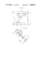
- FIG. 11 shows the rigidity control device utilized for the brace of a building frame, in which the rigidity control device 11 is diagonally disposed between pillars 22 and beams 23 with both ends 24 mounted on gusset plates 24a of pillars 22 and beams 23 by pins 12b and 12c.
- the central pin joint 12 may be changed over to either a flexible or rigid mode. When in the flexible mode, the pin does not resist the axial compressive force in the pin joint but does resist the compressive force in the pin joint while in the rigid mode.
- FIGS. 12(a) and 12(b) show an example in which the rigidity control devices 11 of the three-pin structure on the lowermost story of the building are disposed on both sides of a central pillar 25 as earthquake-resistant pillars.
- the central pin joint 12 is restrained or released from the restraint to change the rigidity of the building according to the characteristics of the earthquake, as shown in FIG. 12(b).
- reference numeral 26 designates braces or earthquake-proof walls.
- a second embodiment 31 of the rigidity control device consists of two members 31a, 31b secured together by restrainer plates 33.
- the connecting rod 34 is mounted on the corresponding planar surfaces of members 31a, 31b to prevent misalignment therebetween.
- Means to actuate the rigidity control device 31, such as a servo motor, may be activated by the control program of the computer 2 (FIG. 1). Namely, the rigidity may be controlled by the computer according to external vibrational forces, such as an earthquake, to change the rigidity of the structural members in each section of the building and the natural period of the whole building, thereby avoiding destructive harmonic resonance.
- FIGS. 14(a) to 14(d) show in greater mechanical detail the rigidity control device shown schematically in FIGS. 13(a) and 13(b), wherein like numbers refer to like members.
- Mounting flanges 37a and 37b are provided to carry threaded rod connecting members 34.
- the threaded pintle 35 is adapted to be rotated by a servo motor 38, which is controlled by the computer 2, through gears 39a, 39b.
- the threaded pintle 35 is rotatably supported by a lower support bracket 40 fixed to the lower side of member 31a and by an upper bracket 41 fixed to the upper side of member 31a.
- Pintle 35 engages through nuts 36 the respective upper and lower restrainer plates 33 provided on opposite surfaces of members 31a and 31b.
- the two restrainer plates 33 are movable simultaneously by rotation of the drive shaft of servo motor 38.
- Restrainer plates 33 are shaped symmetrically about the threaded pintle 35 to provide balance and stability.
- the restrainer plates 33 are provided on the side of member 31a with gudgeons 42 to receive therein in sliding engagement therewith a plain pintle member 43 extending through member 31a.
- FIGS. 15 and 16 show modifications of a drive mechanism for use in association with the device of FIGS. 13 and 14.
- a motor 38' is mounted on the shaft 38a of the threaded pintle 35 and secured to the upper support bracket 41.
- a support bracket 41' for the threaded pintle 35 is mounted directly on the member 31a.
- reference numeral 44 designates a detent for limiting the movement of the restrainer plates 33.
- FIGS. 17(a) to 17(d) show several examples of drive mechanisms mounted on the side of member 31a.
- the threaded pintle 35 and nut 36 for shifting restrainer plates 33 are mounted on one side of the member 31a and restrainer plates 33.
- a plain pintle 43 and gudgeons 42 fixed to the restrainer plates 33 are mounted on the opposite side of the member 31a.
- the servo motor 38, FIG. 17(d) is supported by a bracket 45 protruding sidewise from the member 31a to drive the threaded pintle 35 through gears 39a, 39b.
- pintle nuts 36 and motors 38 may be provided on both sides of the member 31a for increased torque to operate restrainer plates 33.
- FIG. 18 illustrates a rigidity control device 31 attached to a cross brace 31b in a building frame.
- the members 31a, 31b of the rigidity control device 31 are restrained by the restrainer plates 33, a structure capable of resisting compressive and tensile forces is obtained similar to that of an ordinary cross brace.
- the rigidity control device 31 cannot resist the forces of tension or compression when the restrainer plates 33 are separated.
- the restrainer plates 33 are selectively separated by computer command, the rigidity of the entire building is changed.
- FIGS. 19(a) and 19(b) illustrate rigidity control devices 31 according to the present invention used for building pillars 46a and 46b on both sides of pillar 46 to resist earthquake-imposed forces at the lowermost level of the building. Both rigidity control devices are restrained as shown in FIG. 19(a). In FIG. 19(b), a rigidity control device 31 on pillar 46b is no longer restrained, thereby permitting pillar 46b to yield to forces imposed thereon by an earthquake tremor.
- Reference numeral 47 in FIG. 19(a) designates a brace or earthquake-proof wall.
- FIGS. 20 and 21 show rigidity control devices applied to a building brace in which rigidity is maintained with respect to the tensile forces, while being flexible with respect to the axial compressive force.
- members 31b', 31c' (FIG. 20) or members 31a', 31b' (FIG. 21) of a rigidity control device 31' are interconnected with each other by a common pin 51.
- the example of the rigidity control device 31' shown in FIG. 20 is comprised of three members 31a', 31b' and 31c'.
- the pin 51 is provided so that the restrainer plates 33 maintain rigidity with respect to tensile forces between the members 31a' and 31b'.
- the rigidity control device 31A is comprised of two members 31e and 31f so that the restrainer plates 33 have lost motion slots 51a in which pins 51 shift responsive to a compressive force.
- FIG. 22(a) shows rigidity control devices 31' which resist both compressive and tensile forces.
- FIG. 22(b) shows the condition in which the pillar for the axial force at the left side in the drawing is adapted to resist tensile force but not compressive force, while the pillar at the right side is adapted to resist compressive force, but not tensile force.
- the rigidity of respective pillars and whole buildings may be changed responsive to the various forces imposed on a building by earthquake tremors.
- a third embodiment A of a rigidity control device is formed of pin joints 65a, 65b, main members 61, 62 opposed to each other in the dog-legged form and a connecting member 63 disposed between said pin joints 65a, 65b. Both ends of the main members 61, 62 have the pin joints 64a, 64b in common to receive the axial force N therefrom.
- the connecting members 63 disposed between the intermediate pin joints 65a, 65b are removably attached to at least one of pin joints 65a, 65b.
- Members 61a, 61b, 62a, and 62b, constituting the main members 61, 62, and the connecting members 63 have sections defined to have the basic axial rigidity capable of resisting the axial force N for a stable structure.
- the basic rigidity of the rigidity control device A for the axial force resisting member when said member A has the stable structure may be selected according to angle ⁇ of the dog-legged form (an angle made between the axial direction and the member constituting the main members 61, 62).
- the rigidity may be selected in a plurality of stages for the axial force resisting material if the connecting member 63 is detachably disengaged from the intermediate pin joints 65a, 65b at a plurality of positions.
- the connecting member 63 may be either a combination of both the tension resisting member 63a resisting the axially outward movement of the intermediate pin joints 65a, 65b and the compression resisting member 63b resisting the axially inward movement, or a single member which may resist either tension or compression.
- the change-over of the connecting member 63 between the engagement with and disengagement from the pin joints 65a, 65b may be carried out by utilizing the rotational motion (see FIG. 29(a)) of a servo motor, pulse motor, or the like, or by utilizing the linear motion (see FIG. 29(b)) of a hydraulic jack 62c.
- the method of change-over operation is not limited. Since the building avoids the resonant phenomenon caused by an earthquake through the removable engagement of connecting member 63, said change-over operation is effectively carried out when the rigidity is required to be changed. Namely, the connecting member 63 may be automatically controlled on the basis of the control program of the computer so that the rigidity of the members in each section of the building may be changed according to external vibrations forces to change the natural period of the entire building, thereby avoiding destructive resonances.
- the tension resisting member 63a for the connecting member 63 is pivotable about the pin joint 65a and an engaging portion 66a at the end of the connecting member engages the outside of the pin joint 65b.
- the compression resisting member 63b is pivotable about the pin joint 65b and an engaging portion 66b at the end of said member 63b engages the inside of the pin joint 65a to be operated as follows:
- FIG. 24(a) shows both tension resisting member 63a and compression resisting member 63b for the connecting member 63 released from engagement.
- the rigidity control device A provides an unstable structure which does not resist axial force N.
- FIG. 25(a) shows only the compression resisting member 63b engaging the pin joint, in which the compression resisting member 63b works when force N acts on the rigidity control device A.
- the rigidity control device A shows compression resistance. In this case, the rigidity control device A does not resist tension force N.
- FIG. 26(a) shows only the tension resisting member 63a engaging the pin joint 65b, on which the tension resisting member 63a works when force N acts on the rigidity control device A.
- the rigidity control device A shows the tensile resistance. In this case, the rigidity control device A does not resist the compressive force N.
- FIG. 27(a) shows both tension resisting member 63a and compression resisting member 63b engaging the pin joint 65a and 65b, respectively.
- the rigidity control device A may resist either tension or compression, as shown in FIG. 27(b).
- the connecting condition may be varied between the conditions (1) to (4) noted above by the engagement and disengagement of the connecting members 63a and 63b so that the forces on the rigidity control device are as shown in FIG. 28 to permit the two stage change in rigidity.
- the rigidity of building structural members may be varied in a plurality of stages.
- FIGS. 30 and 31(a) to 31(d) illustrate a particular example of the third embodiment of the invention, in which members 61a, 61b, 62a and 62b, made of H-beam structural steel, are interconnected with pin joints 64a, 64b, 65a and 65b and the outboard ends of compression resisting member 63b and tension resisting member 63a are respectively mounted on the intermediate pin joints 65a, 65b.
- the compression resisting member 63b has at its pin-secured end a pulley 72a mounted about the axis of the pin joint 65a and is rotated by a belt 73a drivingly connected to pulleys 71a and 72a.
- a motor 69a to drive belt 73a is fixed to the member 61a by means of a mounting plate 70, FIG. 31(b).
- the compression resisting member 63b is formed on the end with an open L-shaped engaging portion 66b capable of engaging the inside of a shaft of the opposed pin joint 65b by the rotation of the compression resisting member 63b.
- the tension resisting member 63a has similarly at its pin-secured end a pulley 72b mounted about the axis of the pin joint 65b to be pivoted by a motor 69b fixed to the member 62b.
- a closed L-shaped engaging end portion 66a engages the outside of the shaft of the opposed pin joint 65a.
- Reference numerals 74, 75 in FIG. 31(a) designate respectively detents for preventing the engaging portions 66b, 66a of respective compression resisting member 63b and tension resisting member 63a from shifting toward the opposite sides of the pin joints 65a, 65b.
- the compression resisting member 63b is made of I-beam structural steel and the tension resisting member 63a is made of channel beam structural steel.
- FIG. 32 illustrates the inventive device applied to a brace of a building frame in which the rigidity control device A according to the present invention is disposed on a diagonal between pillars 76 and beam 77.
- the seismic motion which varies continuously during an earthquake is analyzed by a computer which commands the rigidity control device A to change the connecting condition so that rigidity may be varied to avoid destructive resonance.
- FIG. 33 shows an example of the rigidity control device A' capable of changing the rigidity of a structural member in a plurality of stages.
- FIGS. 34(a) to 34(f) show the manner of change in rigidity.
- the tension resisting member 63a' for the connecting member 63 is pivotable about the pin joint 65a. Any one of three engaging portions 68a, 68b or 68c near the end may engage the outside of the pin joint 65b, and the rigidity control device A' may change the rigidity of a structural member from complete rigidity to zero rigidity in four stages with respect to compressive forces.
- the compression resisting member 63b' is pivotable about the pin joint 65b such that any one of the three engaging portions 67a, 67b or 67c near the end may engage the inside of the pin joint 65a.
- the rigidity control device A' may change the rigidity in four stages with respect to tensile forces.
- FIG. 35 shows the change in rigidity as the relationship between the axial force N acting on the rigidity control device A' and the displacement ⁇ thereof in the direction of the axial force N.
- resisting member 63 consists of two members 63a and 63b in the example noted above, a single connecting member 63 may resist tension and compression as shown in FIG. 36.
- a fourth embodiment of the rigidity control device as shown in FIG. 37 uses a main member 81 which is arcuately formed to resist bending forces from pillar 83 or cross beam 84.
- a drive unit 82 for applying force perpendicular to a straight line passing through joints 88 at opposite ends of the main member 81.
- the drive unit 82 may be a hydraulic or electric actuator or the like having a servo mechanism. While the size and direction of the force acting on the main member 81 or any change in the linear distance between ends of the member are detected by sensors, the actuator may be operated on the basis of the control program of the computer such as a microcomputer to obtain the proper rigidity with the automatic control. Namely, the rigidity may be controlled by the computer according to external vibrational force such as an earthquake, so that the rigidity and connecting condition of the members in each section of the building may be changed to change the natural period of the whole building and thereby avoid destructive earthquake resonance.
- the rise span ratio should be selected as carefully as possible.
- FIGS. 41(a), 41(b) and 41(c) show schematically the principle in the use of arcuately bent main member 81 of the rigidity control device.
- FIG. 42(c) by applying the force P to the bent member on which the axial force N acts may be adjusted an amount of the axial deformation ⁇ 3 .
- FIGS. 41(a), 41(b) and 41(c) show the examples of tensile force, the fact noted above applies to the compressive force.
- the main members formed in the dog-legged manner may be considered similarly.
- ⁇ xl and ⁇ yl are represented respectively by the following formulas (1) and (2).
- ⁇ x2 and 67 y2 are respectively represented by the following formulas (3) and (4).
- the main member will do with about 3 times section of an ordinary axial force resisting member when controlled to make ⁇ minus, i.e., only to increase the rigidity.
- the section of member used for the rigidity control device will do with about 3 times the section necessary for a linear member when the rigidity is controlled only in the direction of increasing the rigidity.
- FIG. 37 illustrates the utilization of a rigidity control device for a brace.
- the main member 81 which is arcuately bent is disposed on a diagonal in a plane between pillars 83 and beams 84, to be connected at opposite ends to gusset plates 89.
- an actuator 82 hydraulically controlled between the upper corner and the central portion of main member 81 so that force may be applied perpendicularly to the main member 81 by the extension and contraction of the actuator.
- FIG. 38 shows an example of the structure of the actuator 82 for the drive unit, in which oil pressure may be varied by a servo valve 87 to control applied force.
- a piston 86 in the actuator 82 is connected to the main member 81 through pressure plates 91 which secure the main member 81 by bolt means 92. Force may be applied to the main member 81 through pressure plate 91.
- a structural steel H-beam is used for the main member 81.
- FIGS. 45 and 46 are schematic diagrams for analyzing the embodiment of the rigid-release device in which the reaction of the control force acting on the main member 81 through the actuator 82 has to be considered to act on the pillars 83 and beams 84.
- axial force ⁇ N will be applied to the main member 81 for a brace in the action of the control force.
- FIG. 47 shows a graph representing the relationship between the axial force N and the axial deformation ⁇ x (extension and contraction) when the rigidity is varied with the axial variable member.
- the change in rigidity may be controlled by measuring strain between A and B in FIG. 45.
- FIGS. 39 and 40 show also an example of the main member 81 used for a brace, in which an actuator 93 is mounted to interconnect the central portions of a pair of two angle members.
- the actuator 93 for a control unit is received in the brace to provide a compact control unit. Also, it is advantageous in that it is not affected by the reaction of said example.
- the rigidity of the axial resisting member may be easily varied by a combination of bent or dog-legged formed main member and the actuator or the like.
- the rigidity change may be controlled by strain measurement or the like so that it may immediately respond to external vibrational force like an earthquake to provide an element for changing the rigidity and natural frequency of the whole building through the control of the computer. Further, the strength of the member may be easily ensured by enlarging the section of the member.
- the rigidity control device B is an axial force resisting member in which the intermediate portions of dog-legged main members 101, 102 having in common points (shown by pins 104a, 104b in the drawing) which receive the axial force N are interconnected respectively by pins 105a, 105b which are interconnected by a connecting member 103.
- the axis of the connecting member 103 is at a right angle to the direction of the axial force N and has a drive unit 106 receiving force perpendicular to the axial force.
- Members 101a, 101b, 102a and 102b constituting the main members 101, 102 and members 103a, 103b constituting the connecting member 103 have sections defined to provide the basic axial rigidity which may resist the axial force N respectively as a stable structure.
- the basic rigidity for the axial force resisting member may be selected according to an angle ⁇ of the dog-legged member in the stationary condition (angle made between the axial direction and members constituting the main members 101, 102) and the basic rigidity of the connecting member 103. That is, even if the control force by the drive unit 106 of the connecting member 103 is not considered, the basic rigidity may be at will changed according to the angle ⁇ .
- a hydraulic actuator having a servo valve, a digital type hydraulic actuator using an electric pulse motor, and a unit utilizing a nut within which to rotate a bolt by an electric servo motor for varying the gap between members 103a, 103b of the connecting member 103.
- the control force P caused by these drive units 106 acts effectively when it is required that the rigidity be varied continuously to dampen the resonant phenomenon of the building during an earthquake.
- the drive unit 106 may be automatically controlled on the basis of the control program of the computer so that the rigidity of members in each section of the building may be varied according to an external vibrational force to change the natural period of the entire building to avoid destructive resonance.
- a coiled spring or the like may be interposed in parallel to the drive unit 106, if necessary, to ensure predetermined rigidity even if the drive unit 106 is not operated.
- the basic rigidity Ko is unconditionally defined such that the deformation in the direction of the axial force N is proportional to the axial force, while the control force P caused by the drive unit 106 provided on the connecting member 103 varies the basic rigidity Ko. Namely, by further adding or subtracting the control force P to or from the extension or contraction of the connecting member 103, force N may be increased in the direction perpendicular to the direction of the axial force N in the joints of pins 105a, 105b.
- the basic rigidity Ko in the operative direction of the axial force N defines unconditionally the relationship between the axial force N and the deformation ⁇ in the operative direction of the axial force N as shown in the following formula (14) (see FIG. 50(a)), while the deformation may be varied only by ⁇ when the control force P acts on the connecting member (see FIG. 50(b)). Therefore, the same variation of rigidity as that of rigidity K is obtained as shown in the following formula (15): ##EQU1##
- FIGS. 48(a) to 48(c) show respectively an example of a structure of the variable rigidity control device B.
- Opposed main members 101, 102 interconnect respectively members 101a, 101b and 102a, 102b through pins 105a, 105b and interconnect both ends which receive the axial force through common pins 104a, 104b.
- the sections of respective members 101a, 101b, 102a and 102b are of I-beam type sections as shown in FIG. 48(c), they are not limited thereto.
- the joints of the pins 105a, 105b are interconnected by the connecting member 103 which has U-shaped members 103a, 103b disposed back to back as shown in FIG. 48(b) for example and interconnected by a bolt 107.
- the connecting member 103 which has U-shaped members 103a, 103b disposed back to back as shown in FIG. 48(b) for example and interconnected by a bolt 107.
- the member 103a moves toward or away from the other member 103b by means of a nut 108 fixed to the member 103a to provide the control force P.
- Reference numeral 109 in the drawing designates a detent.
- FIG. 48(d) shows an example in which the hydraulic cylinder 106b having a servo valve may be used for control with direct force, instead of the electric servo motor 106a.
- the rigidity K is reduced according to the formula (15) noted above by operating the drive unit 106 to activate the control force for converging a gap between the pins 105a, 105b. Conversely, by activating the control force for diverging the gap between the pins 105a, 105b, ⁇ in the formula (15) takes a minus value to increase the rigidity K.
- the change in the rigidity K may be obtained from the formula (15).
- FIG. 51 shows an example of the rigidity control device B applied to a brace.
- FIG. 52 illustrates rigidity control devices used on both sides of a pillar 110 to be utilized for pillars resisting bending moment during an earthquake.
- the rigidity K of the rigidity control device B may be changed by the control force caused by the operation of the drive unit 106 to avoid destructive resonance.
- Reference numeral 111 in the drawing designates an earthquake-proof wall or brace.
- FIGS. 53(a) to 53(c) show the rigidity control device B interconnected through pins at the lowermost level of the building to be used for a brace.
- the horizontal rigidity at the lowermost level is determined by the control force.
- the rigidity of the brace is adapted to increase against lateral force against the building side such as wind (see FIG. 53(a)).
- the control force is adjusted to reduce the rigidity of the brace against force coming from an earthquake (see FIGS. 53(b) and 53(c)).
- the above-mentioned mechanisms are basically identical with each other except increasing somewhat the horizontal rigidity of the pillar even in the use of rigid joint instead of the pin joint for the connection so long as the pillar is used for an ordinary building.
- the pillar rigid joint facilitates the steel skeleton construction and the arrangement in erection to give advantages in economy and execution.
- Said mechanisms may be also used as dampeners to cancel swings by the control force of the drive unit 106 against large deformation.
- a sixth embodiment of the rigidity control device utilizes the principle of a casting method for metal by which, after dry sand or sand-like substance is enveloped in a film such as vinyl, the internal air is removed by a vacuum pump to compact the sand firmly. When the vacuum pump is stopped and a valve is opened, the sand is returned to its original condition instantly.
- the rigidity control device may be interposed in members such as pillars, beams and braces or between connecting members, earthquake-proof walls and other building members. Further, since sealed sand or sand-like substance may be maintained in a firmly compacted condition for a considerably long time (2-3 hours for example) by closing the valve immediately after the vacuum pump is stopped, the sand may be utilized as a rigidity control device which may be varied as required.
- FIGS. 54(a), 54(b) and 54(c) show rigidity control devices in which sand 123 is sealed in a film 124 to provide a compression resisting member 121 which receives the axial force N in the compressive direction to be varied between a solidly compacted condition and a loosened condition.
- the compression resisting member 121 either resists or does not resist the axial force N.
- the rigidity control device is one in which the film 124 is mounted on a frame member 125 made of metal sections or the like, into which sand 123 is packed and hardened by means of a vacuum pump which removes air from the sand.
- the suction of the pump is carried out from a suction port 126 of the hollow frame member 125 to remove the internal air through a plurality of orifices provided in a filter or the like contacting the sand 123.
- a flexible frame support member 127 interconnects members 121a, 121b constituting the compression resisting member 121 and the frame member 125.
- FIG. 54(b) is a sectional view showing a portion of the rigidity control device when resisting a compressive force.
- pressure in the film 124 is reduced through a suction port 126 by a vacuum pump to provide the required solidly compacted condition of sand 123.
- About 400-500 mmHg will suffice for vacuum pressure.
- FIG. 54(c) shows the condition of no resistance wherein the sand 123 is loosened by returning the pressure in the film 124 to the original condition.
- FIGS. 55(a) and 55(b) show an embodiment of the device wherein the sand 123 is sealed in the film 124 to provide a tension resisting member 122 to receive the axial force N.
- the device may be varied between the firmly compacted condition and the loosened condition so that the tension resisting member 122 may or may not resist the axial force N.
- One member 122a extends through the other member 122b and the sand 123 sealed in the film 124 to transmit stress through the head 122a' during the firmly compacted condition of the sand 123.
- FIG. 56 shows the compression resisting member 121 provided in the cross brace of a building frame.
- the sand 123 resists the axial force in the compressive direction when vacuum pressure is applied to the sand 123 to compact the sand firmly. Conversion between resistance and no resistance is controlled by the computer.
- FIG. 57 shows an example of the tension resisting member 122 having the rigidity device interposed in the joint end of the brace through a support bracket 129. In this case, the rigidity control device can not resist an axial compressive force, but may be varied to resist a tensile force.
- FIG. 58 shows the rigidity control device provided on the lower ends of pillars to receive axial compressive force at the lowermost level of the building, whereby the resistance and non-resistance against the axial compressive force.
- FIG. 59(a) shows the tension resisting members 122 as pillars which are varied between the resistance and non-resistance against the axial tensile force. As shown in FIG. 59(b), the lower end 122' of the tension resisting member 122 engages a support member 130 through the sand 123 sealed by the film 124.
- the pillars for the axial forces shown in FIGS. 58 and 59(a) and 59(b) may be used in combination in a building frame.
- FIGS. 60(a) and 60(b) show structures in which the sand 123 sealed by the film 124 is interposed between the earthquake-proof wall 128, pillar 131 and beam 132.
- the sand may be selectively and firmly compacted by the operation of a vacuum pump.
- the earthquake-proof wall 128 will not resist seismic forces when the sand is in the loosend condition.
- the sixth embodiment utilizes the sand or sand-like substance which is sealed by film, firmly compacted under vacuum-created pressure reduction and returned to the original loosened condition when the pressure is returned to the original condition.
- the sand may be applied to the component members of the building frame or the joints of the component members to vary the rigidity of the building.
Abstract
Description
δxl=Nl/EA+Na.sup.2 l/3EI (1)
δyl=Nal.sup.2 /12EI (2)
δx2=Pal.sup.2 /12EI (3)
δy2=Pl/48EI (4)
(δx2/P)/(δxl/N)=1/4[(l/a) (3/λ)+(a/l)] (5)
a/l=√3/λ (6)
(δx1/P)/(δx1/N)=λ/8√3 (7)
K=N/(δx1+δxz)=(N/δx1) φ=kφ (8)
φ=1/[1=β(λ/8√3)] (9)
β=P/N (10)
σmax=N/A(3.12+0.306βλ) (11)
ΔN=-0.5P=-0.5βN (12)
φ'=φ/(1-0.5β) (13)
Claims (13)
Applications Claiming Priority (12)
| Application Number | Priority Date | Filing Date | Title |
|---|---|---|---|
| JP21540286A JPH0615780B2 (en) | 1986-09-12 | 1986-09-12 | Axial variable stiffness material for building frame |
| JP61-215402 | 1986-09-12 | ||
| JP61-221143 | 1986-09-19 | ||
| JP22114386A JPS6378936A (en) | 1986-09-19 | 1986-09-19 | Variable rigid material of building housing |
| JP25879586A JPS63114771A (en) | 1986-10-30 | 1986-10-30 | Variable rigid material of building housing |
| JP25879486A JPS63114770A (en) | 1986-10-30 | 1986-10-30 | Axial variable rigid material |
| JP61-258795 | 1986-10-30 | ||
| JP61-258794 | 1986-10-30 | ||
| JP61-278427 | 1986-11-21 | ||
| JP27842786A JPH0617598B2 (en) | 1986-11-21 | 1986-11-21 | Axial variable stiffness material for building frame |
| JP30103686A JPS63156170A (en) | 1986-12-17 | 1986-12-17 | Variable rigid building |
| JP61-301036 | 1986-12-17 |
Related Child Applications (1)
| Application Number | Title | Priority Date | Filing Date |
|---|---|---|---|
| US07/400,691 Division US4922667A (en) | 1986-09-12 | 1989-08-30 | Device and method for protecting a building against earthquake tremors |
Publications (1)
| Publication Number | Publication Date |
|---|---|
| US4890430A true US4890430A (en) | 1990-01-02 |
Family
ID=27553911
Family Applications (1)
| Application Number | Title | Priority Date | Filing Date |
|---|---|---|---|
| US07/096,012 Expired - Fee Related US4890430A (en) | 1986-09-12 | 1987-09-10 | Device and method for protecting a building against earthquake tremors |
Country Status (1)
| Country | Link |
|---|---|
| US (1) | US4890430A (en) |
Cited By (21)
| Publication number | Priority date | Publication date | Assignee | Title |
|---|---|---|---|---|
| US5036633A (en) * | 1989-02-07 | 1991-08-06 | Kajima Corporation | Variable damping and stiffness structure |
| US5046290A (en) * | 1989-02-23 | 1991-09-10 | Kajima Corporation | Safety monitoring device for use in active seismic response and wind control system |
| US5065552A (en) * | 1989-02-07 | 1991-11-19 | Kajima Corporation | Active seismic response control system for use in structure |
| US5163256A (en) * | 1989-08-04 | 1992-11-17 | Kajima Corporation | Elasto-plastic damper for structure |
| FR2683558A1 (en) * | 1991-11-07 | 1993-05-14 | Public Works Research Inst | Variable shock-absorption system for a bridge |
| US5259159A (en) * | 1990-11-08 | 1993-11-09 | Shimizu Construction Co., Ltd | Construction having a damping device |
| US5347771A (en) * | 1991-06-20 | 1994-09-20 | Kajima Corporation | High damping device for seismic response controlled structure |
| US5375382A (en) * | 1992-01-21 | 1994-12-27 | Weidlinger; Paul | Lateral force resisting structures and connections therefor |
| US5491938A (en) * | 1990-10-19 | 1996-02-20 | Kajima Corporation | High damping structure |
| US5732802A (en) * | 1994-03-08 | 1998-03-31 | Tsukagoshi; Isamu | Method of damping vibration of structure |
| US6170202B1 (en) * | 1997-06-12 | 2001-01-09 | University Of Puerto Rico | Building system using shape memory alloy members |
| US6397528B1 (en) * | 1997-09-10 | 2002-06-04 | The Cantor Seinuk Group, P.C. | Coupled truss systems with damping for seismic protection of buildings |
| US20030095027A1 (en) * | 2001-06-15 | 2003-05-22 | City University Of Hong Kong | Planar printed circuit-board transformers with effective electromagnetic interference (EMI) shielding |
| US20060207196A1 (en) * | 2003-04-29 | 2006-09-21 | Zoran Petraskovic | System of seismic strengthening of structure |
| US20080163559A1 (en) * | 2007-01-05 | 2008-07-10 | Lee Frank A | Electromagnetically reinforced structural assembly and associated method |
| US20100313496A1 (en) * | 2009-06-15 | 2010-12-16 | Rahimian Ahmad | Energy dissipation damper system in structure subject to dynamic loading |
| US20130118098A1 (en) * | 2011-11-11 | 2013-05-16 | Michael C. Constantinou | Negative stiffness device and method |
| CN103628565A (en) * | 2013-12-09 | 2014-03-12 | 大连理工大学 | Framework-supported swaying-span structural system |
| US9206616B2 (en) | 2013-06-28 | 2015-12-08 | The Research Foundation For The State University Of New York | Negative stiffness device and method |
| US20180334826A1 (en) * | 2017-05-17 | 2018-11-22 | WSP USA Buildings Inc. | Asymmetric damping system for, and method of, protecting structures subjected to external dynamic forces |
| CN115075643A (en) * | 2022-07-08 | 2022-09-20 | 安徽工业大学 | Controllable post system that sways based on earthquake early warning system |
Citations (16)
| Publication number | Priority date | Publication date | Assignee | Title |
|---|---|---|---|---|
| US849638A (en) * | 1906-12-28 | 1907-04-09 | Roy G Platt | Folding rule. |
| US2352565A (en) * | 1942-12-10 | 1944-06-27 | Edward H Ranson | Movable mast support |
| US2965399A (en) * | 1959-02-19 | 1960-12-20 | Angelo A Rizzuto | Hinged butt joint |
| US3184261A (en) * | 1963-10-18 | 1965-05-18 | Charles H Young | Collapsible and extendable standard |
| FR1425887A (en) * | 1965-03-02 | 1966-01-24 | B C Barton & Son Ltd | rigid structural element formed from an assembly of similar parts |
| US3796017A (en) * | 1972-04-24 | 1974-03-12 | M Meckler | Hydraulic structural apparatus |
| JPS5219436A (en) * | 1975-08-05 | 1977-02-14 | Ohbayashigumi Ltd | Frame with flexible diagonal beams |
| SU623923A1 (en) * | 1975-12-08 | 1978-09-15 | Военный Инженерный Краснознаменный Институт Им.А.Ф.Можайского | Screen for protecting foundations of buildings, structures against vibration of base |
| SU838014A1 (en) * | 1979-09-21 | 1981-06-15 | Ленинградский Ордена Ленина Институтинженеров Железнодорожного Транспортаим. Акад. B.H.Образцова | Arrangement for protecting structure in earthquake |
| DE3015997A1 (en) * | 1980-04-25 | 1981-11-05 | Messerschmitt-Bölkow-Blohm GmbH, 8000 München | Extensible, telescopic mast with working platform - has position stabilising nozzles or propellers on platform in extended state |
| US4389141A (en) * | 1980-12-31 | 1983-06-21 | Mobil Oil Corporation | Marine structure having a deck or work platform supported by absorbing mechanisms |
| SU1030496A1 (en) * | 1981-08-07 | 1983-07-23 | Ордена Ленина Институт Физики Земли Им.О.Ю.Шмидта | Method for protecting development area against seismic action |
| US4429496A (en) * | 1980-12-24 | 1984-02-07 | University Of Southern California | Method and apparatus for active control of flexible structures |
| JPS60164520A (en) * | 1984-02-08 | 1985-08-27 | Mitsubishi Electric Corp | Earthquake resisting device |
| US4587777A (en) * | 1981-10-09 | 1986-05-13 | General Dynamics Corporation/Convair Div. | Deployable space truss beam |
| SU1328465A1 (en) * | 1985-12-03 | 1987-08-07 | Государственный проектный институт "Ленпроектстальконструкция" | Metal tied-up skeleton for multistorey earthquake-proof building |
-
1987
- 1987-09-10 US US07/096,012 patent/US4890430A/en not_active Expired - Fee Related
Patent Citations (16)
| Publication number | Priority date | Publication date | Assignee | Title |
|---|---|---|---|---|
| US849638A (en) * | 1906-12-28 | 1907-04-09 | Roy G Platt | Folding rule. |
| US2352565A (en) * | 1942-12-10 | 1944-06-27 | Edward H Ranson | Movable mast support |
| US2965399A (en) * | 1959-02-19 | 1960-12-20 | Angelo A Rizzuto | Hinged butt joint |
| US3184261A (en) * | 1963-10-18 | 1965-05-18 | Charles H Young | Collapsible and extendable standard |
| FR1425887A (en) * | 1965-03-02 | 1966-01-24 | B C Barton & Son Ltd | rigid structural element formed from an assembly of similar parts |
| US3796017A (en) * | 1972-04-24 | 1974-03-12 | M Meckler | Hydraulic structural apparatus |
| JPS5219436A (en) * | 1975-08-05 | 1977-02-14 | Ohbayashigumi Ltd | Frame with flexible diagonal beams |
| SU623923A1 (en) * | 1975-12-08 | 1978-09-15 | Военный Инженерный Краснознаменный Институт Им.А.Ф.Можайского | Screen for protecting foundations of buildings, structures against vibration of base |
| SU838014A1 (en) * | 1979-09-21 | 1981-06-15 | Ленинградский Ордена Ленина Институтинженеров Железнодорожного Транспортаим. Акад. B.H.Образцова | Arrangement for protecting structure in earthquake |
| DE3015997A1 (en) * | 1980-04-25 | 1981-11-05 | Messerschmitt-Bölkow-Blohm GmbH, 8000 München | Extensible, telescopic mast with working platform - has position stabilising nozzles or propellers on platform in extended state |
| US4429496A (en) * | 1980-12-24 | 1984-02-07 | University Of Southern California | Method and apparatus for active control of flexible structures |
| US4389141A (en) * | 1980-12-31 | 1983-06-21 | Mobil Oil Corporation | Marine structure having a deck or work platform supported by absorbing mechanisms |
| SU1030496A1 (en) * | 1981-08-07 | 1983-07-23 | Ордена Ленина Институт Физики Земли Им.О.Ю.Шмидта | Method for protecting development area against seismic action |
| US4587777A (en) * | 1981-10-09 | 1986-05-13 | General Dynamics Corporation/Convair Div. | Deployable space truss beam |
| JPS60164520A (en) * | 1984-02-08 | 1985-08-27 | Mitsubishi Electric Corp | Earthquake resisting device |
| SU1328465A1 (en) * | 1985-12-03 | 1987-08-07 | Государственный проектный институт "Ленпроектстальконструкция" | Metal tied-up skeleton for multistorey earthquake-proof building |
Cited By (25)
| Publication number | Priority date | Publication date | Assignee | Title |
|---|---|---|---|---|
| US5036633A (en) * | 1989-02-07 | 1991-08-06 | Kajima Corporation | Variable damping and stiffness structure |
| US5065552A (en) * | 1989-02-07 | 1991-11-19 | Kajima Corporation | Active seismic response control system for use in structure |
| US5046290A (en) * | 1989-02-23 | 1991-09-10 | Kajima Corporation | Safety monitoring device for use in active seismic response and wind control system |
| US5163256A (en) * | 1989-08-04 | 1992-11-17 | Kajima Corporation | Elasto-plastic damper for structure |
| US5491938A (en) * | 1990-10-19 | 1996-02-20 | Kajima Corporation | High damping structure |
| US5259159A (en) * | 1990-11-08 | 1993-11-09 | Shimizu Construction Co., Ltd | Construction having a damping device |
| US5347771A (en) * | 1991-06-20 | 1994-09-20 | Kajima Corporation | High damping device for seismic response controlled structure |
| FR2683558A1 (en) * | 1991-11-07 | 1993-05-14 | Public Works Research Inst | Variable shock-absorption system for a bridge |
| US5375382A (en) * | 1992-01-21 | 1994-12-27 | Weidlinger; Paul | Lateral force resisting structures and connections therefor |
| US5732802A (en) * | 1994-03-08 | 1998-03-31 | Tsukagoshi; Isamu | Method of damping vibration of structure |
| US6170202B1 (en) * | 1997-06-12 | 2001-01-09 | University Of Puerto Rico | Building system using shape memory alloy members |
| US6397528B1 (en) * | 1997-09-10 | 2002-06-04 | The Cantor Seinuk Group, P.C. | Coupled truss systems with damping for seismic protection of buildings |
| US20030095027A1 (en) * | 2001-06-15 | 2003-05-22 | City University Of Hong Kong | Planar printed circuit-board transformers with effective electromagnetic interference (EMI) shielding |
| US20060207196A1 (en) * | 2003-04-29 | 2006-09-21 | Zoran Petraskovic | System of seismic strengthening of structure |
| US20080163559A1 (en) * | 2007-01-05 | 2008-07-10 | Lee Frank A | Electromagnetically reinforced structural assembly and associated method |
| US20100313496A1 (en) * | 2009-06-15 | 2010-12-16 | Rahimian Ahmad | Energy dissipation damper system in structure subject to dynamic loading |
| US8136309B2 (en) * | 2009-06-15 | 2012-03-20 | Rahimian Ahmad | Energy dissipation damper system in structure subject to dynamic loading |
| US20130118098A1 (en) * | 2011-11-11 | 2013-05-16 | Michael C. Constantinou | Negative stiffness device and method |
| US8857110B2 (en) * | 2011-11-11 | 2014-10-14 | The Research Foundation For The State University Of New York | Negative stiffness device and method |
| US9206616B2 (en) | 2013-06-28 | 2015-12-08 | The Research Foundation For The State University Of New York | Negative stiffness device and method |
| CN103628565A (en) * | 2013-12-09 | 2014-03-12 | 大连理工大学 | Framework-supported swaying-span structural system |
| CN103628565B (en) * | 2013-12-09 | 2015-10-28 | 大连理工大学 | Frame-brace waves across structural system |
| US20180334826A1 (en) * | 2017-05-17 | 2018-11-22 | WSP USA Buildings Inc. | Asymmetric damping system for, and method of, protecting structures subjected to external dynamic forces |
| CN115075643A (en) * | 2022-07-08 | 2022-09-20 | 安徽工业大学 | Controllable post system that sways based on earthquake early warning system |
| CN115075643B (en) * | 2022-07-08 | 2024-04-09 | 安徽工业大学 | Controllable swing column system based on earthquake early warning system |
Similar Documents
| Publication | Publication Date | Title |
|---|---|---|
| US4922667A (en) | Device and method for protecting a building against earthquake tremors | |
| US4890430A (en) | Device and method for protecting a building against earthquake tremors | |
| Kurata et al. | Forced vibration test of a building with semi‐active damper system | |
| US5713162A (en) | Aseismatic system for constructions such as buildings, dry bridges, tanks and like | |
| Sivakumaran | Seismic response of multi-storey steel buildings with flexible connections | |
| Baktash et al. | Seismic tests on a model shear wall with friction joints | |
| US20040154258A1 (en) | Building structure configured to exhibit a prescribed load-deflection relationship when a force is applied thereto | |
| US5671569A (en) | Seismic response controlled frame of bending deformation control type | |
| JPH0615780B2 (en) | Axial variable stiffness material for building frame | |
| JPH0686774B2 (en) | Variable bending stiffness device for structures | |
| JP2749391B2 (en) | Building frame | |
| JPH01203571A (en) | Variable rigidity construction of building frame | |
| JP3520487B2 (en) | Seismic reinforcement structure of existing buildings | |
| JP3463085B2 (en) | Seismic building | |
| JP7409969B2 (en) | Lifting mechanism and reinforced concrete columns and reinforced concrete structures equipped with the same | |
| JP3690468B2 (en) | Seismic reinforcement structure | |
| JPH10266620A (en) | Vibration damping frame structure and construction method therefor | |
| US20040098930A1 (en) | Sliding concave foundation system | |
| JP3028034B2 (en) | Damping structure | |
| JP3283949B2 (en) | Soil structure of unit building | |
| JP2001140497A (en) | Earthquake-resistant house | |
| JP3028033B2 (en) | Damping structure | |
| JP3254322B2 (en) | Seismic isolation device | |
| JPS5924955B2 (en) | flat bottom cylindrical tank | |
| JPH01131741A (en) | Variable rigid brace |
Legal Events
| Date | Code | Title | Description |
|---|---|---|---|
| AS | Assignment |
Owner name: KAJIMA CORPORATION, A CORP. OF JAPAN Free format text: ASSIGNMENT OF ASSIGNORS INTEREST.;ASSIGNORS:KOBORI, TAKUJI;YAMADA, SHUNICHI;KAMAGATA, SHUICHI;REEL/FRAME:004779/0218 Effective date: 19870818 Owner name: KAJIMA CORPORATION, A CORP. OF JAPAN,JAPAN Free format text: ASSIGNMENT OF ASSIGNORS INTEREST;ASSIGNORS:KOBORI, TAKUJI;YAMADA, SHUNICHI;KAMAGATA, SHUICHI;REEL/FRAME:004779/0218 Effective date: 19870818 |
|
| FEPP | Fee payment procedure |
Free format text: PAYOR NUMBER ASSIGNED (ORIGINAL EVENT CODE: ASPN); ENTITY STATUS OF PATENT OWNER: LARGE ENTITY |
|
| FPAY | Fee payment |
Year of fee payment: 4 |
|
| FEPP | Fee payment procedure |
Free format text: PAYOR NUMBER ASSIGNED (ORIGINAL EVENT CODE: ASPN); ENTITY STATUS OF PATENT OWNER: LARGE ENTITY Free format text: PAYER NUMBER DE-ASSIGNED (ORIGINAL EVENT CODE: RMPN); ENTITY STATUS OF PATENT OWNER: LARGE ENTITY |
|
| REMI | Maintenance fee reminder mailed | ||
| FPAY | Fee payment |
Year of fee payment: 8 |
|
| SULP | Surcharge for late payment | ||
| REMI | Maintenance fee reminder mailed | ||
| LAPS | Lapse for failure to pay maintenance fees | ||
| STCH | Information on status: patent discontinuation |
Free format text: PATENT EXPIRED DUE TO NONPAYMENT OF MAINTENANCE FEES UNDER 37 CFR 1.362 |
|
| FP | Lapsed due to failure to pay maintenance fee |
Effective date: 20020102 |