US4845414A - Method of protecting the electric drive of a vehicle against overload - Google Patents
Method of protecting the electric drive of a vehicle against overload Download PDFInfo
- Publication number
- US4845414A US4845414A US07/120,121 US12012187A US4845414A US 4845414 A US4845414 A US 4845414A US 12012187 A US12012187 A US 12012187A US 4845414 A US4845414 A US 4845414A
- Authority
- US
- United States
- Prior art keywords
- electric drive
- power
- vehicle
- speed
- current
- Prior art date
- Legal status (The legal status is an assumption and is not a legal conclusion. Google has not performed a legal analysis and makes no representation as to the accuracy of the status listed.)
- Expired - Fee Related
Links
Images


Classifications
-
- H—ELECTRICITY
- H02—GENERATION; CONVERSION OR DISTRIBUTION OF ELECTRIC POWER
- H02H—EMERGENCY PROTECTIVE CIRCUIT ARRANGEMENTS
- H02H7/00—Emergency protective circuit arrangements specially adapted for specific types of electric machines or apparatus or for sectionalised protection of cable or line systems, and effecting automatic switching in the event of an undesired change from normal working conditions
- H02H7/08—Emergency protective circuit arrangements specially adapted for specific types of electric machines or apparatus or for sectionalised protection of cable or line systems, and effecting automatic switching in the event of an undesired change from normal working conditions for dynamo-electric motors
- H02H7/085—Emergency protective circuit arrangements specially adapted for specific types of electric machines or apparatus or for sectionalised protection of cable or line systems, and effecting automatic switching in the event of an undesired change from normal working conditions for dynamo-electric motors against excessive load
-
- Y—GENERAL TAGGING OF NEW TECHNOLOGICAL DEVELOPMENTS; GENERAL TAGGING OF CROSS-SECTIONAL TECHNOLOGIES SPANNING OVER SEVERAL SECTIONS OF THE IPC; TECHNICAL SUBJECTS COVERED BY FORMER USPC CROSS-REFERENCE ART COLLECTIONS [XRACs] AND DIGESTS
- Y02—TECHNOLOGIES OR APPLICATIONS FOR MITIGATION OR ADAPTATION AGAINST CLIMATE CHANGE
- Y02T—CLIMATE CHANGE MITIGATION TECHNOLOGIES RELATED TO TRANSPORTATION
- Y02T10/00—Road transport of goods or passengers
- Y02T10/60—Other road transportation technologies with climate change mitigation effect
- Y02T10/72—Electric energy management in electromobility
Definitions
- the invention relates to a method of protecting the electric drive of a vehicle, in particular an electric automobile, against overload when the nominal (i.e. the "rated") power is temporarily exceeded.
- An advantage of electric vehicles is that they can be overloaded for short periods or, in other words, their nominal (i.e. "rated") power (maximum permissible contnuous power) can be exceeded for a short period.
- this advantage is used for starting and accelerating and for driving up slopes and ramps.
- the operation at overload must be limited timewise in order to protect the electric drive from damage.
- One overload protection is provided by the thermal monitoring of all of the drive components.
- specified temperature thresholds When specified temperature thresholds are exceeded, the power of the drive is automatically reduced. The reduction in power leads to a reduction in the traveling speed. The speed reduction occurs as a surprise to the vehicle operator, which can lead to dangerous traffic situations.
- Another possiblity for overload protection is to monitor operating current integrated over time.
- a circuit configuration is known from German Patent DE-PS 24 31 540 for protecting an electrical machine against excessive heating.
- the rotor temperature is influenced by limiting the motor current in such a way that the maximum permissible temperature is not exceeded.
- the square of the measured current is integrated and the integral value is compared with a temperature value corresponding to the nominal power.
- the motor current is reduced in the case of excessive integral values. If this control is used for electric vehicles, surprising effects can again occur for the vehicle operator because the maximum speed of the vehicle depends on the previous history of the driving power. It is not possible to select a predictable and reproducible driving power (maximum speed).
- a method for protecting the electric drive of a vehicle, especially an electric automobile, against overload when the nominal (i.e. the "rated") power is temporarily exceeded which comprises measuring the traveling speed of the vehicle, and automatically limiting the traveling speed to prevent the exceeding, at least for a short period of a continuous speed obtained at nominal operation of the electric drive corresponding to traveling resistances independent of acceleration,
- the method is implemented as soon as the nominal (i.e. the "rated") power of the nominal current of the electric drive is exceeded. Short-term power exceeding the nominal power is then made available for acceleration only.
- the nominal power of the electric drive which includes the components from the energy source used for driving the vehicle wheels, is equal to the maximum permissible continuous power of the drive.
- This continuous power corresponds to a maximum permissible continuous speed of the vehicle which occurs with the given resistances to travel that are independent of acceleration.
- the rolling resistance, the slope resistance, the aerodynamic drag and the curve resistance can, for example, be considered as traveling resistances which are independent of acceleration.
- the method according to the invention provides reproducible driving performance because the maximum permissible continuous speed is based on the power of the nominal operation and not on the maximum power of the drive. Unexpected events caused by a sudden reduction in power and speed initiated by overload protection can be avoided.
- a method which comprises determining a maximum permissible continuous speed from current traveling resistances and from the nominal power of the electric drive, comparing the continuous speed with the currently existing vehicle speed, and reducing the drive power (or the drive current) to the nominal power (or nominal current) whenever the vehicle speed is equal to or greater than the maximum permissible continuous speed.
- the nominal value of the power or current can be exceeded for a short period during acceleration and until the continuous speed corresponding to the nominal operation of the drive is reached. No acceleration can then occur beyond this continuous speed.
- the measured values which are used are preferably those which can be determined directly within the vehicle. These are, for example, the drive current, the drive voltage, the rotational speed of the electrical motor and the speed of the vehicle.
- the determination of the continuous speed can take place by means of Equation (12) given below.
- a method which comprises limiting the vehicle power whenever the difference between the electrical power to be provided under given operating conditions and the nominal electrical power of the drive is greater than the acceleration power of the electrical vehicle divided by the efficiency of the electric drive.
- a method which comprises limiting or reducing the drive current of the electrical drive to a nominal current in order to limit the vehicle power.
- all of the measured data which is necessary can be determined directly within the vehicle.
- the efficiency of the electric drive is equal to the quotient of the power at the wheel of the vehicle and the electrical power of the drive.
- a method which comprises limiting the drive power or the drive current with a time constant of a few seconds (such as 10 seconds). This is done in order to avoid a sudden change between the drive current and the nominal current in the case of a power reduction. In this way, an acceleration process is not abruptly interrupted.
- FIG. 1 is a graph showing the variation of speed according to time when a vehicle is accelerated
- FIG. 2 is a flow chart showing the method in accordance with one embodiment of the invention.
- FIG. 3 is a flow chart showing the method in accordance with another embodiment of the invention.
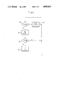
- FIG. 4 is a block circuit diagram showing a circuit configuration for carrying out the method.
- the resistance to travel F is obtained by adding
- the individual resistances can be determined from the following equations:
- A vehicle area
- Equation (5) If the constants are combined into k, Equation (5) becomes:
- the acceleration resistance F b is composed of a translatory part and a rotational part.
- the rotational part is made up of the sum of the moments of inertia referred to the wheel (multiplication by the square of the gear ratios) multiplied by the acceleration b.
- the rotational proportion is taken into account in the form of a mass factor c.
- the acceleration resistance is therefore given by the equation:
- the transmission ratio uml i is obtained from the measurement of the speed v (km/h), the motor speed n (r.p.m.) and the tire radius r (m).
- the different transmission rations uml i can be associated with known mass factors c i , such that:
- the acceleration b can be determined from the change in speed per unit time (V 2 ,V 1 ,t).
- the acceleration resistance F b is calculated from Equations (7) to (9).
- the power requirement P r at the wheel of a vehicle can, in principle, be determined from the constants (m, g, f r , k, r, c j ) and measured values (v, n, alpha, v w ).
- the slope alpha and the angular velocity are not immediately available from a measurement made at the vehicle.
- both the parameters can be combined as a first approximation in order to gibe the value of an apparent slope angle alpha because head wind and rear wind act like an upward or a downwards slop, when conisdered from within the vehicle.
- the power P r at the wheels is obtained from the measurement of the drive voltage U and the drive current I as:
- ETA is the total efficiency of the electric drive from the electrical power supply to the wheel.
- ETA is fundamentally known and can be specified by means of a characteristic field, as a function of power, rotational speed and transmission ratio.
- Equation (11) contains only constants of known magnitude and measured quantities (I, U, v, n), which can be directly determined within the vehicle, the slope angle alpha can be determined at any time from within the vehicle.
- the continuous speed v D can be determined by solving Equation (12).
- An iteration method can be used, for example, in order to solve Equation (12).
- FIG. 1 there is seen a more detailed explanation by showing, on one hand, the timewise variation of the speed during acceleration at the nominal power P n and, on the other hand, at an overload power P k permitted for a short period.
- the vehicle At the nominal power P n , the vehicle is accelerated up to the continuous speed v D (according to the definition).
- the overload power P k At the overload power P k , the vehicle is more strongly accelerated. however, the acceleration process is interrupted at a time A in order to avoid overloading the drive.
- the drive is controlled down to nominal operation and the vehicle continues to travel at its continuous speed v D . Two methods are described for this below, using FIGS. 2 and 3.
- an interrogation 10 determines whether or not the current I of the electric drive is greater than the nominal current I n . If this is not the case, there is no overload and a possible current limitation is eliminated in a step 11. The current interrogation 10 can then be repeated at specified intervals. If the measured drive current I is greater than the nominal current I n , the continuous speed v D is calculated in a step 12 using Equation (12). The calculation can take place by means of an appropriate electrical circuit or by means of a computer. A further interrogation 13 then determines whether the traveling speed v of the vehicle is greater than the calculated continuous speed v D . If this is not the case, the interrogation cycle is repeated.
- step 14 If the traveling speed v is greater than the continuous speed v D , a limitation of the drive current I to the nominal current In is undertaken in a step 14. The interrogation cycle is then repeated.
- the current limitation in step 14 does not take place abruptly but is instead subject to a time constant of, for example, 10 seconds. This avoids an acceleration procedure being abruptly interrupted as soon as the continuous speed v D is reached.
- an interrogation 15 first checks whether or not the vehicle is traveling. If this is the case, an interrogation 16 determines whether or not the current I of the electric drive is greater than the nominal current I n . If this is not the case, the vehicle is not being driven with overload an and a possible current limitation possibly present is eliminated in a step 17. If the measured current I is greater than the nominal current I n , the acceleration power P b is determined in a step 18 in accordance with Equation (16), using the derivative of the traveling speed v with respect to time (by differentiation). An interrogation 19 then follows in accordance with Equation (17). If Equation (17) is satisfied, the interrogation cycle is repeated. Otherwise, the current I of the electric drive is limited to the nominal current I n by a step 20. In this case as well, it is desirable to undertake the current limitation gradually (with a time constant).
- the method operates independently of all disturbing influences which are located outside the vehicle and can only be determined by calculation (wind speed, slope, curve travel, road surface) because these are obtained by differentiation in accordance with Equation (17). Parameters which are normally measured in the vehicle provide information.
- FIG. 4 shows a circuit configuration by means of which the step 18 and the interrogation 19 of FIG. 3 can be effected.
- the measured values of the motor speed n and the vehicle speed v are used by an operator 22 to determine the transmission ration Uml by eans of Equation (8) and the associated mass factor c i determined.
- the number 1 is added to the mass factor c i in an adder 23.
- the acceleration b is formed from the measured speed value v in a differentiator 24 and the acceleration b is multiplied by the vehicle mass m in a multiplier 25.
- the result from the multiplier 25 is multiplied by the result from the adder 23 in a multiplier 26 disposed downstream.
- the output signal of the multiplier 26 is divided by the efficiency ETA of the electric drive in a divider element 27.
- the result is multiplied by the measured speed value v in a further multiplier 28. This gives a signal which is equal to the acceleration power P b divided by the efficiency ETA.
- the interrogation 19 is effected by a multiplier 29, an addition element 30 and a threshold element 31.
- the product of the measured values of the drive current I and the drive voltage U is formed in the multiplier 29.
- the quotient of the acceleration power P b and the efficiency ETA which has already been obtained, is subtracted from this product value in the addition or summation element 30.
- the difference value is supplied to the threshold element 31 where it is compared with the specified value of the maximum permissible electrical continuous power P e1D of the electric drive. If the difference value is greater than P e1D , a current limitation is unnecessary. This information is transmitted through the output A for further processing.
Landscapes
- Electric Propulsion And Braking For Vehicles (AREA)
Applications Claiming Priority (2)
| Application Number | Priority Date | Filing Date | Title |
|---|---|---|---|
| DE19863638946 DE3638946A1 (de) | 1986-11-14 | 1986-11-14 | Verfahren zum schutz des elektroantriebes eines fahrzeuges gegen ueberlast |
| DE3638946 | 1986-11-14 |
Publications (1)
| Publication Number | Publication Date |
|---|---|
| US4845414A true US4845414A (en) | 1989-07-04 |
Family
ID=6313949
Family Applications (1)
| Application Number | Title | Priority Date | Filing Date |
|---|---|---|---|
| US07/120,121 Expired - Fee Related US4845414A (en) | 1986-11-14 | 1987-11-13 | Method of protecting the electric drive of a vehicle against overload |
Country Status (4)
| Country | Link |
|---|---|
| US (1) | US4845414A (de) |
| EP (1) | EP0270850B1 (de) |
| JP (1) | JPS63136903A (de) |
| DE (2) | DE3638946A1 (de) |
Cited By (4)
| Publication number | Priority date | Publication date | Assignee | Title |
|---|---|---|---|---|
| US20050137060A1 (en) * | 2003-12-23 | 2005-06-23 | Caterpillar Inc. | Retarding control for an electric drive machine |
| US6982534B2 (en) | 2001-10-10 | 2006-01-03 | Ebm-Papst St. Georgen Gmbh & Co. Kg | Method for operating an electronically commutated motor, and motor for carrying out one such method |
| US20070284170A1 (en) * | 2006-06-13 | 2007-12-13 | Kuras Brian D | Retarding control for hydromechanical drive machine |
| WO2011148050A2 (en) * | 2010-05-25 | 2011-12-01 | Sandvik Mining And Construction Oy | Rock drilling rig, method for transfer drive of the same, and speed controller |
Families Citing this family (3)
| Publication number | Priority date | Publication date | Assignee | Title |
|---|---|---|---|---|
| US5123081A (en) * | 1990-07-27 | 1992-06-16 | Raymond Corporation | Temperature control system for motors and power components of a material handling vehicle |
| JPH0511703U (ja) * | 1991-07-22 | 1993-02-12 | 株式会社四国製作所 | 電動車の走行制御装置 |
| DE102011005000B4 (de) * | 2011-03-02 | 2023-07-20 | Bayerische Motoren Werke Aktiengesellschaft | Geschwindigkeitsabregelung zur Vermeidung des Überschreitens einer Maximalgeschwindigkeit eines Kraftfahrzeugs |
Citations (7)
| Publication number | Priority date | Publication date | Assignee | Title |
|---|---|---|---|---|
| US3243681A (en) * | 1962-11-26 | 1966-03-29 | Yale And Towne Inc | Transistorized speed control for industrial truck |
| US3551773A (en) * | 1967-03-22 | 1970-12-29 | Eaton Yale & Towne | Drive system for an electric truck |
| US3944899A (en) * | 1973-06-30 | 1976-03-16 | Joseph Lucas (Industries) Limited | Control circuit for electrically driven vehicles |
| JPS525111A (en) * | 1975-06-30 | 1977-01-14 | Hitachi Ltd | Safety apparatus for electric car |
| US4423362A (en) * | 1982-05-19 | 1983-12-27 | General Electric Company | Electric vehicle current regulating system |
| JPS5995616A (ja) * | 1982-11-25 | 1984-06-01 | Tokai Rika Co Ltd | 車両定速走行装置 |
| EP0184339A1 (de) * | 1984-11-08 | 1986-06-11 | Mitsubishi Denki Kabushiki Kaisha | Elektrisch angetriebenes Schienenfahrzeug |
Family Cites Families (2)
| Publication number | Priority date | Publication date | Assignee | Title |
|---|---|---|---|---|
| DE2431540C2 (de) * | 1974-07-01 | 1984-09-13 | Brown, Boveri & Cie Ag, 6800 Mannheim | Schaltungsanordnung zum Schutz einer elektrischen Maschine gegen zu hohe Erwärmung mit einer Simulationseinrichtung |
| US4490656A (en) * | 1983-06-30 | 1984-12-25 | The Singer Company | Overload protection in a motor control system |
-
1986
- 1986-11-14 DE DE19863638946 patent/DE3638946A1/de active Granted
-
1987
- 1987-11-07 EP EP87116463A patent/EP0270850B1/de not_active Expired - Lifetime
- 1987-11-07 DE DE8787116463T patent/DE3774087D1/de not_active Expired - Fee Related
- 1987-11-13 JP JP62285666A patent/JPS63136903A/ja active Pending
- 1987-11-13 US US07/120,121 patent/US4845414A/en not_active Expired - Fee Related
Patent Citations (7)
| Publication number | Priority date | Publication date | Assignee | Title |
|---|---|---|---|---|
| US3243681A (en) * | 1962-11-26 | 1966-03-29 | Yale And Towne Inc | Transistorized speed control for industrial truck |
| US3551773A (en) * | 1967-03-22 | 1970-12-29 | Eaton Yale & Towne | Drive system for an electric truck |
| US3944899A (en) * | 1973-06-30 | 1976-03-16 | Joseph Lucas (Industries) Limited | Control circuit for electrically driven vehicles |
| JPS525111A (en) * | 1975-06-30 | 1977-01-14 | Hitachi Ltd | Safety apparatus for electric car |
| US4423362A (en) * | 1982-05-19 | 1983-12-27 | General Electric Company | Electric vehicle current regulating system |
| JPS5995616A (ja) * | 1982-11-25 | 1984-06-01 | Tokai Rika Co Ltd | 車両定速走行装置 |
| EP0184339A1 (de) * | 1984-11-08 | 1986-06-11 | Mitsubishi Denki Kabushiki Kaisha | Elektrisch angetriebenes Schienenfahrzeug |
Cited By (11)
| Publication number | Priority date | Publication date | Assignee | Title |
|---|---|---|---|---|
| US6982534B2 (en) | 2001-10-10 | 2006-01-03 | Ebm-Papst St. Georgen Gmbh & Co. Kg | Method for operating an electronically commutated motor, and motor for carrying out one such method |
| US20050137060A1 (en) * | 2003-12-23 | 2005-06-23 | Caterpillar Inc. | Retarding control for an electric drive machine |
| US6986727B2 (en) | 2003-12-23 | 2006-01-17 | Caterpillar Inc. | Retarding control for an electric drive machine |
| US20070284170A1 (en) * | 2006-06-13 | 2007-12-13 | Kuras Brian D | Retarding control for hydromechanical drive machine |
| WO2011148050A2 (en) * | 2010-05-25 | 2011-12-01 | Sandvik Mining And Construction Oy | Rock drilling rig, method for transfer drive of the same, and speed controller |
| WO2011148050A3 (en) * | 2010-05-25 | 2012-01-19 | Sandvik Mining And Construction Oy | Rock drilling rig, method for transfer drive of the same, and speed controller |
| CN102905932A (zh) * | 2010-05-25 | 2013-01-30 | 山特维克矿山工程机械有限公司 | 岩石钻机、用于岩石钻机的转移驱动的方法和速度控制器 |
| AU2011257101B2 (en) * | 2010-05-25 | 2013-10-03 | Sandvik Mining And Construction Oy | Rock drilling rig, method for transfer drive of the same, and speed controller |
| RU2523880C1 (ru) * | 2010-05-25 | 2014-07-27 | Сандвик Майнинг Энд Констракшн Ой | Установка для бурения по коренным породам, способ транспортировки указанной установки и регулятор скорости транспортировки установки |
| CN102905932B (zh) * | 2010-05-25 | 2016-01-20 | 山特维克矿山工程机械有限公司 | 岩石钻机、用于岩石钻机的转移驱动的方法和速度控制器 |
| EP2576280A4 (de) * | 2010-05-25 | 2017-04-12 | Sandvik Mining and Construction Oy | Steinbohrvorrichtung, verfahren zur übertragung von deren drehmoment und geschwindigkeitskontrollgerät |
Also Published As
| Publication number | Publication date |
|---|---|
| JPS63136903A (ja) | 1988-06-09 |
| DE3638946A1 (de) | 1988-05-26 |
| EP0270850A1 (de) | 1988-06-15 |
| EP0270850B1 (de) | 1991-10-23 |
| DE3774087D1 (de) | 1991-11-28 |
| DE3638946C2 (de) | 1989-04-20 |
Similar Documents
| Publication | Publication Date | Title |
|---|---|---|
| US7091678B2 (en) | Device and method for controlling prime mover | |
| US6208097B1 (en) | Traction vehicle adhesion control system without ground speed measurement | |
| CA1252182A (en) | Control system for maintaining traction in a rolling stock | |
| US4765430A (en) | Method and arrangement for propulsion regulation of an automobile | |
| US7509193B2 (en) | Method and device for limiting the driving speed of a motor vehicle | |
| US4799161A (en) | Control apparatus for maintaining traction in electric rolling stock | |
| EP0219238B1 (de) | Anlage und Verfahren für eine Blockierschutz-Bremssteuerung | |
| US4763263A (en) | Propulsion control using longitudinal acceleration to determine slip thresholds | |
| US6758087B2 (en) | Method, system and storage medium for determining a vehicle reference speed | |
| EP0145374A2 (de) | Automatische Geschwindigkeitssteuerungssysteme | |
| US4823269A (en) | Wheel spin control apparatus | |
| SE461515B (sv) | Anordning foer att begraensa motoreffekten vid ett fordon daa instabila koerningstillstaand upptraeder | |
| US5841254A (en) | Torque maximization and vibration control for AC locomotives | |
| US5898281A (en) | Method and device for the common regulation of several electric motors driving the driving wheels of a motor vehicle | |
| US4845414A (en) | Method of protecting the electric drive of a vehicle against overload | |
| EP0310270B1 (de) | Verfahren und System zur Steuerung des Radschlupfes eines Fahrzeugs | |
| EP0576013B1 (de) | Strassenoberfläche-Zustands-Sensor zur Bremsensteuerung | |
| US5117933A (en) | Drive slip regulating system for a four-wheel drive vehicle | |
| US5113820A (en) | Method of avoiding excessive engine drag torque | |
| KR950021968A (ko) | 토크추정을 갖춘 와류 브레이크장치 | |
| JPH04501592A (ja) | 駆動すべり制御装置 | |
| JPS63306253A (ja) | 車輪加速スリップ制御装置 | |
| JPH0599015A (ja) | 牽引制御装置 | |
| JPH03203508A (ja) | 電気牽引車両の空転またはスキッドの防止方法並びにかかる車両の空転またはスキッドの検出及び粘着力の測定における該方法の使用 | |
| US4037143A (en) | Means in a motor-driven rail-vehicle |
Legal Events
| Date | Code | Title | Description |
|---|---|---|---|
| AS | Assignment |
Owner name: BBC BROWN, BOVERI AKTIENGESSELSCHAFT, A CORP. OF G Free format text: ASSIGNMENT OF ASSIGNORS INTEREST.;ASSIGNORS:ANGELIS, JURGEN;SCHERF, HARTMUT;HAASE, HELMUT;REEL/FRAME:005063/0746 Effective date: 19871106 |
|
| FEPP | Fee payment procedure |
Free format text: PAYOR NUMBER ASSIGNED (ORIGINAL EVENT CODE: ASPN); ENTITY STATUS OF PATENT OWNER: LARGE ENTITY |
|
| FPAY | Fee payment |
Year of fee payment: 4 |
|
| REMI | Maintenance fee reminder mailed | ||
| LAPS | Lapse for failure to pay maintenance fees | ||
| FP | Lapsed due to failure to pay maintenance fee |
Effective date: 19970709 |
|
| STCH | Information on status: patent discontinuation |
Free format text: PATENT EXPIRED DUE TO NONPAYMENT OF MAINTENANCE FEES UNDER 37 CFR 1.362 |