US4782706A - Holding device for mounting an electric transducer - Google Patents
Holding device for mounting an electric transducer Download PDFInfo
- Publication number
- US4782706A US4782706A US07/012,443 US1244387A US4782706A US 4782706 A US4782706 A US 4782706A US 1244387 A US1244387 A US 1244387A US 4782706 A US4782706 A US 4782706A
- Authority
- US
- United States
- Prior art keywords
- holding
- rings
- holding device
- holding rings
- clamping
- Prior art date
- Legal status (The legal status is an assumption and is not a legal conclusion. Google has not performed a legal analysis and makes no representation as to the accuracy of the status listed.)
- Expired - Fee Related
Links
Images




Classifications
-
- G—PHYSICS
- G01—MEASURING; TESTING
- G01G—WEIGHING
- G01G19/00—Weighing apparatus or methods adapted for special purposes not provided for in the preceding groups
- G01G19/08—Weighing apparatus or methods adapted for special purposes not provided for in the preceding groups for incorporation in vehicles
- G01G19/12—Weighing apparatus or methods adapted for special purposes not provided for in the preceding groups for incorporation in vehicles having electrical weight-sensitive devices
-
- G—PHYSICS
- G01—MEASURING; TESTING
- G01B—MEASURING LENGTH, THICKNESS OR SIMILAR LINEAR DIMENSIONS; MEASURING ANGLES; MEASURING AREAS; MEASURING IRREGULARITIES OF SURFACES OR CONTOURS
- G01B7/00—Measuring arrangements characterised by the use of electric or magnetic techniques
- G01B7/16—Measuring arrangements characterised by the use of electric or magnetic techniques for measuring the deformation in a solid, e.g. by resistance strain gauge
- G01B7/24—Measuring arrangements characterised by the use of electric or magnetic techniques for measuring the deformation in a solid, e.g. by resistance strain gauge using change in magnetic properties
-
- G—PHYSICS
- G01—MEASURING; TESTING
- G01G—WEIGHING
- G01G19/00—Weighing apparatus or methods adapted for special purposes not provided for in the preceding groups
- G01G19/02—Weighing apparatus or methods adapted for special purposes not provided for in the preceding groups for weighing wheeled or rolling bodies, e.g. vehicles
- G01G19/07—Weighing apparatus or methods adapted for special purposes not provided for in the preceding groups for weighing wheeled or rolling bodies, e.g. vehicles for weighing aircraft
-
- G—PHYSICS
- G01—MEASURING; TESTING
- G01G—WEIGHING
- G01G3/00—Weighing apparatus characterised by the use of elastically-deformable members, e.g. spring balances
- G01G3/12—Weighing apparatus characterised by the use of elastically-deformable members, e.g. spring balances wherein the weighing element is in the form of a solid body stressed by pressure or tension during weighing
- G01G3/15—Weighing apparatus characterised by the use of elastically-deformable members, e.g. spring balances wherein the weighing element is in the form of a solid body stressed by pressure or tension during weighing measuring variations of magnetic properties
-
- G—PHYSICS
- G01—MEASURING; TESTING
- G01L—MEASURING FORCE, STRESS, TORQUE, WORK, MECHANICAL POWER, MECHANICAL EFFICIENCY, OR FLUID PRESSURE
- G01L1/00—Measuring force or stress, in general
- G01L1/14—Measuring force or stress, in general by measuring variations in capacitance or inductance of electrical elements, e.g. by measuring variations of frequency of electrical oscillators
Definitions
- the present invention refers to a holding device for the mounting of an electric transducer, particularly a shear-strain gauge, within a tubular construction part, particularly an airplane axle, the transducer consisting of a coil part having two magnet coils spaced apart from each other and of a disk part which has a disk which in normal position extends equidistantly between the magnet coils, with two holding rings arranged at a given distance axially from each other, the coil part being adapted to be fastened to one holding ring and the disk part being adapted to be fastened to the other holding ring.
- Such shear-strain gauges are known from U.S. Pat. No. 4,269,070. They serve for installation in an axle of an aircraft in order to detect the deformation of the axle there. Strain values determined thereby are required for determining the weight and the center of gravity of the aircraft. In this way, optimum loading can, in particular, be effected.
- the shear-strain gauge is held by holding rings in the airplane axle which is developed as a tubular structural part, radially directed screw bolts arranged on the holding rings being screwed in until they rest against the inner wall of the airplane axle.
- the holding rings (16, 17) are developed with radial resilience and with a smaller outside diameter than the inside diameter of the tubular structural part (1) and they have radially protruding holding lugs (23) which can rest under initial spring tension against the inner wall of the tubular structural part (1), and the holding rings (16, 17) have support parts (28, 28'), the coil part (18) being adapted to be fastened to the support part (28) of the one holding ring (17) and the disk part (20) being adapted to be fastened to the support part (28') of the other holding ring (16).
- the holding rings are thus held in the tubular structural part in simple manner solely by the radial tension with which they rest resiliently against the inner wall of the tubular structural part.
- This radial tension can be changed by changing the size of the holding extensions.
- the support parts (28, 28') which serve for the attachment are preferably developed on the holding rings (16, 17), so that they can be machined together with the holding rings without any great problems as to tolerance.
- Coil part (18) and/or disk part (20) can thus be adapted to be fastened in favorable manner on the holding ring (16, 17) by a screw fastening.
- the coil part (18) and/or disk part (20) can be fastened to a support element (29, 30) which can be connected to the holding ring (16, 17).
- guide groove (31) and guide extension (36, 36') are preferably of V-shaped cross section.
- the guide extension (36, 36') has an axial slot (37) which opens outwards towards the bottom of the guide groove (31), then the guide extension can adapt itself to the guide groove, overcoming the manufacturing tolerances.
- the guide grooves (31) preferably extend in a plane which is parallel to the longitudinal axis of the tubular structural part (1), said plane extending vertically insofar as possible. In this way the transducer can be adjusted by displacing the support elements in the guide grooves with its lengthwise direction into the horizontally extending neutral plane of bend of the tubular structural part.
- a recess (38, 39) extending axially to the longitudinal axis of the tubular structural part (1) can be passed through on same by a fastening screw (40, 41) which can be screwed into a threaded hole (32, 33) of the holding ring (16, 17).
- the support element can also be shifted for the adjustment.
- the recess (38) is preferably a slot which extends in the same direction as the guide groove (31).
- the support elements (29, 30) of both holding rings (16, 17) are arranged on the end sides of the holding rings (16, 17) facing a mouth opening (5) of the tubular structural part (1) which forms a mounting opening.
- the threaded hole (32) of that holding ring (16) which is closer to the mounting opening be a continuous hole whose inside diameter is greater than the largest outside diameter of a wrench by which the fastening screw (34) of that holding ring (17) which is further from the mounting opening can be screwed.
- the holding rings (16, 17) have at least two holding lugs (23) which are diametrically opposite each other, the holding lugs (23) being shifted about 90° to the support parts (28, 28'), then the position of the holding rings in the tubular structural part is unequivocally defined in simple manner.
- a shift in position of the holding rings by a bending of the tubular structural part which is to be detected is avoided in the manner that the holding lugs (23) are webs of slight axial length.
- the holding rings (16, 17) can have radially inward extending grip extensions (24) in the region of the holding lugs (23). These grip extensions (24) are particularly easily grasped if they have undercut recesses (25). The recesses (25) of the grip extensions (24) can be preferably engaged behind by radially inwardly movable clamping jaws (58, 58') of a clamping device (54).
- Such a clamping device for the radially inward clamping of the holding rings of a holding device of the type described above can have two clamping jaws (58, 58') which are movable radially towards each other and are provided at their radially outward directed ends with gripping hooks (60) which are arranged approximately in circumferential direction and by which the circular extensions (grip extensions 24) of the holding rings (16, 17) can be gripped behind.
- the clamping jaws (58, 58') are preferably movable parallel to each other.
- both holding rings can be installed simultaneously into the tubular structural part.
- the clamping device can have a stop (61) which limits the movement of introduction of the clamping device into the tubular structural part (1).
- an installation template for installing the holding rings of a holding device of the above-described type into a tubular structural part can be developed in such a manner that the holding rings (16, 17) can be connected by the installation template (47) corresponding to their installation length so as to form an assembly unit (48) correctly associated with each other.
- the installation template (47) preferably has two fastening extensions (50, 51) which are connected to each other and can be detachably fastened to the sides of the holding rings (16, 17) facing the mounting opening (assembly unit 48) of the tubular structural part (1).
- the installation template (47) can preferably be fastened to two support parts (28, 28') of the holding rings (16, 17) which are associated axially with each other.
- the installation template (47) is provided with guide extensions (36') corresponding to the guide extensions (36) of the support elements (29, 30) and can be fastened to the holding rings (16, 17) by means of fastening screws (52, 53) which can be screwed into the threaded holes (32, 33) of the holding rings (16, 17), then disassembly of the installation template can be effected after the insertion of the holding rings in the same manner as the assembling of the support elements is effected.
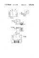
- FIG. 1 is a cross section through a view of an airplane axle
- FIG. 1a is a cross section through a top view of the airplane axle of FIG. 1;
- FIG. 2 is a front view of an outer holding ring
- FIG. 2a is a side view, in section, of the holding ring of FIG. 2;
- FIG. 2b is a rear view of the holding ring of FIG. 2;
- FIG. 2c is a top view in, section of, the holding ring of FIG. 2;
- FIG. 3 is a front view of an inner holding ring
- FIG. 3a is a side view, in section, of the holding ring of FIG. 3;
- FIG. 3b is a rear view of the holding ring of FIG. 3;
- FIG. 3c is a top view, in section, of the holding ring of FIG. 3;
- FIG. 4 is a front view of an outer support element
- FIG. 4a is a top view of the support element of FIG. 4;
- FIG. 4b is a rear view of the support element of FIG. 4;
- FIG. 4c is an enlarged portion of the support element of FIG. 4a;
- FIG. 5 is a front view of an inner support element
- FIG. 5a is a top view of the support element of FIG. 5;
- FIG. 5b is a rear view of the support element of FIG. 5;
- FIG. 5c is an enlarged portion of the support element of FIG. 5a;
- FIG. 6 is a view of the holding device with resistance gauges in half section
- FIG. 6a is a front view of the holding device of FIG. 6;
- FIG. 6b is a front view of the holding device of FIG. 6a;
- FIG. 6c is a rear view of the holding device of FIG. 6a;
- FIG. 7 is an assembly unit, consisting of installation template and holding rings, seen in half section;
- FIG. 8 is an adjustment tool, seen in front view
- FIG. 8a is the adjustment tool of FIG. 8, in top view
- FIG. 8b is an enlarged sectional view of the head of the adjustment tool of FIG. 8;
- FIG. 8c is a top view of the head of FIG. 8b;
- FIG. 9 is a view of a cable guide ring
- FIG. 9a is a side view of the cable guide ring of FIG. 9, seen in section;
- FIG. 10 is a perspective view of a clamping device
- FIG. 11 is a side view of a shear strain gauge.
- FIGS. 1 and la show a half of an airplane axle 1 for the nose wheel of an airplane.
- the rim 3 of a wheel 4 is turnably mounted on this tubular airplane axle via antifriction bearing 2.
- a drive cap 6 which covers the outer mouth opening 5 and which has a drive pin 7 which extends coaxially into the guide axle 1.
- a tachogenerator 8 which is arranged fixed against rotation in the aircraft axle 1 can be driven.
- the connecting cable 9 of the tachogenerator 8 is prevented, by a cable guide ring 10 and a protector plate 11 borne by the latter, from placing itself in uncontrolled manner against a shear strain measuring system arranged in the inner region of the airplane axle 1 alongside the cable guide ring 10.
- the connecting cable is conducted to the central region of the airplane axle 1 without it being possible to influence the measured values of the shear strain measuring arrangement.
- the shear strain gauges 14 are held in the airplane axle 1 by means of a holding ring 16 which is closer to the mouth opening 5 and a holding ring 17 which is at a given distance therefrom and further away from the mouth opening 5.
- the two shear strain gauges 14 extend axially alongside of each other in the horizontal neutral plane of bend of the airplane axle 1 so that they are not deflected vertically out of their zero position when the landing gear is not under load.
- FIG. 11 shows such a shear strain gauge 14. It consists of a coil part 18 which can be fastened to the holding ring 16 and has two magnet coils 19 which are spaced apart from each other and a disk part 20 which has a disk 21 which in unloaded normal position is equidistant between the magnet coils 19.
- the coil part 18 also has a cable connection 22 for the connecting of the connecting cable 13.
- the holding ring 16 is shown on a larger scale in FIGS. 2 to 2c and the holding ring 17 is shown on a larger scale in FIGS. 3 to 3c.
- Both holding rings 16 and 17 are radially resilient and have radially protruding holding lugs 23.
- the latter are arranged in two vertically diametrically opposite groups of two holding lugs 23 each. They are formed by arms of slight axial length.
- the diameter measured over the holding lugs 23 is somewhat greater than the inside diameter of the airplane axle so that the holding rings 16 and 17 which bear the shear strain gauge 14 are held under initial spring tension in the airplane axle 1.
- the holding rings 16 and 17 Radially inwardly directed and opposite each other the holding rings 16 and 17 have grip extensions 24 developed in the region of the holding lugs 23 with recesses 25, which can be gripped behind. These recesses 25 can be gripped behind by clamping jaws of a clamping device, shown in FIG. 10, and the holding rings 16 and 17 are thus elastically radially inwardly deformable for insertion into the airplane axle.
- the holding rings 17 and 16 also have radially inwardly directed support parts 28 and 28' developed thereon.
- support elements 29 and 30 can be fastened by screw attachments, as shown in FIGS. 4 to 4c and 5 to 5c, they, in their turn, bearing the coil parts 18 and disk parts 20.
- the support parts 28 and 28' are provided on their sides facing the mouth opening 5 with guide grooves 31 of V-shaped cross section which extend vertically transverse to the lengthwise direction of the airplane axle 1.
- the support parts 28 and 28' are provided with continuous threaded holes 32 and 33 which are developed axially to the airplane axle 1 and centrally to the guide grooves 31.
- the inside diameter of the threaded hole 32 is sufficiently large that a wrench, in particular an Allen wrench, can be passed from the mouth opening 5 through the threaded hole 32 in order to tighten or loosen the Allen screws 34 which fasten the support elements 30 to the support part 28.
- the support elements 29 and 30 have holding pedestals 35 on which the coil parts 18 and the disk parts 20 can be screwed fast in their correct position already before installation into the holding rings 16 and 17 which have already been inserted in the airplane axle 1.
- the support elements 29 and 30 have guide extensions 36 of V-shaped cross section which are developed in a manner corresponding to the guide grooves 31 and extend into them.
- These guide extensions 36 have, both centrally and on their side regions, slots 37 extending in the lengthwise direction of the guide extensions 36, said slots opening outwards towards the bottom of the guide groove 31.
- the guide extensions 36 are somewhat elastic transverse to their lengthwise dimension and can adapt themselves in centering fashion to the guide groove 31, overcoming the manufacturing tolerances.
- the recesses 38 of the support elements 29 are developed as slots with their length corresponding to the lengthwise direction of the guide grooves 31 so that the support element 29 bearing the coil part 28 can be shifted in the guide groove 31. In this way, an adjustment in position to a precise coaxial position of coil part 18 and disk part 20 can be effected.
- the support element 29 is provided on its side facing away from the guide extension with stops 42 extending coaxial to the recess 38 and transverse to the length of the guide extension.
- an adjustment tool 43 such as shown in FIGS. 8 to 8c.
- This adjustment tool has a sleeve-like head 44 whose inner bore 45 has a diameter corresponding approximately to the head of the fastening screw 40.
- the cylindrical outer contour 46 of the head 44 is eccentric to the inner bore 45 and has a diameter which corresponds approximately to the spacing of the stops 42.
- the holding rings 16 and 17 are connected by installation templates 47 to form an assembly unit, as shown in FIG. 7.
- the installation templates 47 have two fastening extensions 50 and 51 which are connected to each other by an arm 49 which extends through the central recess of the holding ring 16, said fastening extensions being adapted to be fastened by means of fastening screws 52 and 53 to the side of the support parts 28 and 29 facing the mouth opening 5 of the airplane axle 1.
- the fastening extensions 50 and 51 are developed with the same guide extensions 36', slots 37' and recesses 38' and 39' as the support elements 29 and 30 and also grip via the guide extensions 36' into the guide grooves 31.
- fastening screws 52 and 53 also correspond to the fastening screws 40 and 34, disassembly of the installation templates 47 after insertion of the assembly unit 48 into the airplane axle 1 is possible. It is effected, first of all, by loosening the fastening screws 52, then loosening the fastening screws 51 by means of a wrench passed through the threaded hole 32, and then removing the installation template through the central recess in the holding ring 16.
- clamping device 54 shown in FIG. 10 is used.
- This clamping device 54 has a cylindrical body 55 with two pairs of grooves arranged at right angles to each other, namely clamping grooves 56 and guide grooves 57, which are developed extending axially on the cylindrical outer surface of the body 55.
- clamping grooves 56 there extend the claw-shaped ends of clamping jaws 58 and 58'.
- the inner clamping jaws 58 are movable in opposite direction to the outer clamping jaws 58'.
- the clamping jaws 58 are provided at their end extending into the lower clamping groove 56 with gripping hooks 60, not shown, while the clamping jaws 58' have gripping hooks 60 at the end thereof extending into the upper clamping groove 56'.
- the lateral pushing-on is effected until the end sides of the arms 48 come against the axial ends of the guide grooves 57.
- the clamping jaws 58 and 58' are moved radially inward and the holding rings 16 and 17 are elastically deformed in such a manner that the mounting unit 48 can be introduced with the clamping device 54 into the airplane axle 1. This takes place until the radial widening of the cylindrical body 55 which forms a stop at 61 comes against the mouth opening 5. In this way, the exact positioning of the holding rings 16 and 17 in the airplane axle 1 is reached.
- the assembly unit 48 is installed. There is now effected the removal as described above of the installation template 47 and the installation of the shear strain gauge 14, provided with the support elements 29 and 30, from the mouth opening 5.
- the cable guide ring 10 shown in FIGS. 9 and 9a is, in principle, of the same construction and is inserted in the same manner as the holding rings 16 and 17. It also has grip extensions 24 and holding lugs 23.
- the cable guide ring 10 has holding lugs 23 spaced axially apart in two planes. In order to obtain an uncoupling of the two planes of the holding lugs 23, the cable guide ring 10 is substantially separated by radial slits 62 into two axially adjacent parts rings.
Landscapes
- Physics & Mathematics (AREA)
- General Physics & Mathematics (AREA)
- Engineering & Computer Science (AREA)
- Aviation & Aerospace Engineering (AREA)
- Clamps And Clips (AREA)
- Force Measurement Appropriate To Specific Purposes (AREA)
- Magnetic Resonance Imaging Apparatus (AREA)
Applications Claiming Priority (2)
| Application Number | Priority Date | Filing Date | Title |
|---|---|---|---|
| DE19863604030 DE3604030A1 (de) | 1986-02-08 | 1986-02-08 | Halteeinrichtung zur halterung eines elektrischen wandlers |
| DE3604030 | 1986-02-08 |
Publications (1)
| Publication Number | Publication Date |
|---|---|
| US4782706A true US4782706A (en) | 1988-11-08 |
Family
ID=6293725
Family Applications (1)
| Application Number | Title | Priority Date | Filing Date |
|---|---|---|---|
| US07/012,443 Expired - Fee Related US4782706A (en) | 1986-02-08 | 1987-02-09 | Holding device for mounting an electric transducer |
Country Status (5)
| Country | Link |
|---|---|
| US (1) | US4782706A (de) |
| EP (1) | EP0232535B1 (de) |
| JP (1) | JPH0621824B2 (de) |
| DE (2) | DE3604030A1 (de) |
| ES (1) | ES2026131T3 (de) |
Cited By (16)
| Publication number | Priority date | Publication date | Assignee | Title |
|---|---|---|---|---|
| US4928531A (en) * | 1987-04-11 | 1990-05-29 | Vdo Adolf Schindling Ag | Fastening device for the attaching of an electric transmitter |
| US5205514A (en) * | 1990-10-20 | 1993-04-27 | Vdo Adolf Schindling Ag | Arrangement of at least one sensor on the landing gear of an aircraft for measuring its weight and position of center of gravity |
| US5257756A (en) * | 1990-09-13 | 1993-11-02 | Adolf Schindling Ag | Arrangement of sensors on the landing gear of an aircraft for measuring the weight and position of center of gravity of the aircraft |
| US5521827A (en) * | 1994-09-16 | 1996-05-28 | General Electrodynamics Corporation | On-board aircraft weighting and center of gravity determing apparatus and method |
| US5681998A (en) * | 1992-06-09 | 1997-10-28 | Yazaki Corporation | Load measuring device for a vehicle |
| US6032090A (en) * | 1997-05-06 | 2000-02-29 | General Electrodynamics Corporation | System and method for on-board determination of aircraft weight and load-related characteristics |
| US20060114126A1 (en) * | 2002-07-16 | 2006-06-01 | Francis Gibert | Apparatus for monitoring an aircraft flap and application of a dynamometric rod |
| US20080125980A1 (en) * | 2004-12-24 | 2008-05-29 | El-Bakry Murad | Apparatus And Method For Measuring Loads Sustained By A Bearing Pin |
| US20100264263A1 (en) * | 2009-04-19 | 2010-10-21 | Rockwell Collins, Inc. | Integrated load sensing system |
| US8033500B1 (en) | 2008-04-28 | 2011-10-11 | Rockwell Collins, Inc. | Actuator load path monitoring system |
| US20120280092A1 (en) * | 2011-05-03 | 2012-11-08 | Airbus Operations (S.A.S.) | Fixture device for an aircraft tubing |
| US8496204B1 (en) | 2011-07-06 | 2013-07-30 | Rockwell Collins, Inc. | Method and system for minimizing axial backlash in a dual load path fail-safe aircraft actuator system |
| US20140055283A1 (en) * | 2011-08-01 | 2014-02-27 | Greenwave Reality, Pte Ltd. | Multiple and interchangeable meter reading probes |
| US8714479B1 (en) | 2011-08-11 | 2014-05-06 | Rockwell Collins, Inc. | Centering, release and reset mechanism |
| US20150034395A1 (en) * | 2013-07-30 | 2015-02-05 | The Boeing Company | Modal acoustic aircraft weight system |
| US10837823B2 (en) | 2017-02-03 | 2020-11-17 | Safran Landing Systems | Aircraft landing gear |
Families Citing this family (1)
| Publication number | Priority date | Publication date | Assignee | Title |
|---|---|---|---|---|
| FR3062722B1 (fr) * | 2017-02-03 | 2019-04-19 | Safran Landing Systems | Cible de mesure magnetique |
Citations (2)
| Publication number | Priority date | Publication date | Assignee | Title |
|---|---|---|---|---|
| US3521484A (en) * | 1967-03-06 | 1970-07-21 | Electro Dev Corp | Load measuring system |
| US4269070A (en) * | 1979-09-28 | 1981-05-26 | Weico Corporation | Strain/deflection sensitive variable reluctance transducer assembly |
Family Cites Families (3)
| Publication number | Priority date | Publication date | Assignee | Title |
|---|---|---|---|---|
| US3426586A (en) * | 1966-06-17 | 1969-02-11 | Blh Electronics | Aircraft weight measurements |
| US3975685A (en) * | 1975-01-30 | 1976-08-17 | Allmanna Svenska Elektriska Aktiebolaget | Magnetoelastic shear force measuring means for measuring shear stress in tubular axles |
| FR2545170B1 (fr) * | 1983-04-29 | 1986-02-21 | Sfena | Procede de realisation de bague palier de support d'elements pour pieces cylindriques en creux ou en plein et bague palier ainsi obtenue |
-
1986
- 1986-02-08 DE DE19863604030 patent/DE3604030A1/de not_active Withdrawn
- 1986-12-22 ES ES198686117912T patent/ES2026131T3/es not_active Expired - Lifetime
- 1986-12-22 EP EP86117912A patent/EP0232535B1/de not_active Expired - Lifetime
- 1986-12-22 DE DE8686117912T patent/DE3681580D1/de not_active Expired - Lifetime
-
1987
- 1987-02-05 JP JP62023710A patent/JPH0621824B2/ja not_active Expired - Lifetime
- 1987-02-09 US US07/012,443 patent/US4782706A/en not_active Expired - Fee Related
Patent Citations (2)
| Publication number | Priority date | Publication date | Assignee | Title |
|---|---|---|---|---|
| US3521484A (en) * | 1967-03-06 | 1970-07-21 | Electro Dev Corp | Load measuring system |
| US4269070A (en) * | 1979-09-28 | 1981-05-26 | Weico Corporation | Strain/deflection sensitive variable reluctance transducer assembly |
Cited By (25)
| Publication number | Priority date | Publication date | Assignee | Title |
|---|---|---|---|---|
| US4928531A (en) * | 1987-04-11 | 1990-05-29 | Vdo Adolf Schindling Ag | Fastening device for the attaching of an electric transmitter |
| US5257756A (en) * | 1990-09-13 | 1993-11-02 | Adolf Schindling Ag | Arrangement of sensors on the landing gear of an aircraft for measuring the weight and position of center of gravity of the aircraft |
| US5205514A (en) * | 1990-10-20 | 1993-04-27 | Vdo Adolf Schindling Ag | Arrangement of at least one sensor on the landing gear of an aircraft for measuring its weight and position of center of gravity |
| US5681998A (en) * | 1992-06-09 | 1997-10-28 | Yazaki Corporation | Load measuring device for a vehicle |
| US5684254A (en) * | 1992-06-09 | 1997-11-04 | Yazaki Corporation | Load measuring device for a vehicle |
| US5521827A (en) * | 1994-09-16 | 1996-05-28 | General Electrodynamics Corporation | On-board aircraft weighting and center of gravity determing apparatus and method |
| US6032090A (en) * | 1997-05-06 | 2000-02-29 | General Electrodynamics Corporation | System and method for on-board determination of aircraft weight and load-related characteristics |
| US20060114126A1 (en) * | 2002-07-16 | 2006-06-01 | Francis Gibert | Apparatus for monitoring an aircraft flap and application of a dynamometric rod |
| US7299702B2 (en) * | 2002-07-16 | 2007-11-27 | Fgb Instrumentation | Apparatus for monitoring an aircraft flap and application of a dynamometric rod |
| CN101103259B (zh) * | 2004-12-24 | 2011-10-05 | 空中客车英国运营有限责任公司 | 用于测量轴承销所承受的负载的设备和方法 |
| US20080125980A1 (en) * | 2004-12-24 | 2008-05-29 | El-Bakry Murad | Apparatus And Method For Measuring Loads Sustained By A Bearing Pin |
| US7747396B2 (en) * | 2004-12-24 | 2010-06-29 | Airbus Uk Limited | Apparatus and method for measuring loads sustained by a bearing pin |
| US8033500B1 (en) | 2008-04-28 | 2011-10-11 | Rockwell Collins, Inc. | Actuator load path monitoring system |
| US20100264263A1 (en) * | 2009-04-19 | 2010-10-21 | Rockwell Collins, Inc. | Integrated load sensing system |
| US8191824B2 (en) | 2009-04-19 | 2012-06-05 | Rockwell Collins, Inc. | Integrated load sensing system |
| US9400066B2 (en) * | 2011-05-03 | 2016-07-26 | Airbus Operations (S.A.S.) | Fixture device for an aircraft tubing |
| US20120280092A1 (en) * | 2011-05-03 | 2012-11-08 | Airbus Operations (S.A.S.) | Fixture device for an aircraft tubing |
| US8496204B1 (en) | 2011-07-06 | 2013-07-30 | Rockwell Collins, Inc. | Method and system for minimizing axial backlash in a dual load path fail-safe aircraft actuator system |
| US8941509B2 (en) * | 2011-08-01 | 2015-01-27 | Greenwave Systems Pte. Ltd. | Multiple and interchangeable meter reading probes |
| US9046390B2 (en) | 2011-08-01 | 2015-06-02 | Greenwave Systems Pte Ltd | Image sensing meter reading probe |
| US20140055283A1 (en) * | 2011-08-01 | 2014-02-27 | Greenwave Reality, Pte Ltd. | Multiple and interchangeable meter reading probes |
| US8714479B1 (en) | 2011-08-11 | 2014-05-06 | Rockwell Collins, Inc. | Centering, release and reset mechanism |
| US20150034395A1 (en) * | 2013-07-30 | 2015-02-05 | The Boeing Company | Modal acoustic aircraft weight system |
| US9551609B2 (en) * | 2013-07-30 | 2017-01-24 | The Boeing Company | Modal acoustic aircraft weight system |
| US10837823B2 (en) | 2017-02-03 | 2020-11-17 | Safran Landing Systems | Aircraft landing gear |
Also Published As
| Publication number | Publication date |
|---|---|
| ES2026131T3 (es) | 1992-04-16 |
| JPH0621824B2 (ja) | 1994-03-23 |
| EP0232535A3 (en) | 1989-08-30 |
| DE3604030A1 (de) | 1987-08-13 |
| EP0232535B1 (de) | 1991-09-18 |
| DE3681580D1 (de) | 1991-10-24 |
| EP0232535A2 (de) | 1987-08-19 |
| JPS62191728A (ja) | 1987-08-22 |
Similar Documents
| Publication | Publication Date | Title |
|---|---|---|
| JPH0621824B2 (ja) | 電気的な変換器を保持するための保持装置 | |
| JP2933993B2 (ja) | ケーブル用支持構造 | |
| US9457443B2 (en) | Machine locating pin | |
| US3889542A (en) | Wheel mounting apparatus | |
| EP0769326A2 (de) | Vorrichtung zur Befestigung einer Trennkammer auf einer mechanischen Spannvorrichtung | |
| US5601295A (en) | Tool holder system for industrial cutting tools | |
| CN111174066A (zh) | 车轮夹持装置 | |
| US5492441A (en) | Clamping device for connecting machine spindles with tool holders | |
| JPH0346685B2 (de) | ||
| US6439063B1 (en) | Wheel load transducer | |
| CA1272110A (en) | Vehicle skid prevention device employing a centrifugal chain assembly | |
| CN115166282B (zh) | 汽车轮速测量装置及使用方法 | |
| CN115157147B (zh) | 一种汽车传感器检测用夹具 | |
| US20230303199A1 (en) | Vehicle stem and methods thereof | |
| CN213859067U (zh) | 转子盘的分解工具 | |
| CN211708762U (zh) | 一种车床自动化装夹用工装 | |
| US4973188A (en) | Pointer bushing | |
| CN118811620A (zh) | 架线牵引机 | |
| EP0370179A2 (de) | Universalgerät zur Abziehen von Kugellager-Innenringen | |
| EP3272444B1 (de) | Flexible kupplung zur befestigung einer spannzange an eine zugstange | |
| US5193283A (en) | Bicycle wheel spike inpecting and adjusting device | |
| KR102001239B1 (ko) | 풍동 시험모형의 정렬을 위한 무충격 위치핀 장탈착장치 및 이를 이용한 밸런스와 시험모형의 장탈착방법 | |
| US6079522A (en) | Bicycle brake adapter | |
| KR102615850B1 (ko) | 스티어링 로봇 거치대의 축 중심 찾기용 스티어링 휠 센터 세팅 지그 | |
| EP0253269A3 (de) | Halteklammer zum Ausrichten der Karosserie unfallbeschädigter Autos, insbesondere der aus Metallblech bestehenden Befestigungsflächen für Oberteile von Macphersonradaufhängungen |
Legal Events
| Date | Code | Title | Description |
|---|---|---|---|
| AS | Assignment |
Owner name: VDO ADOLF SCHINDLING AG, A CORP. OF GERMANY,GERMA Free format text: ASSIGNMENT OF ASSIGNORS INTEREST;ASSIGNORS:KISTER, HORST;SCHWAB, JEAN-FRANCOIS;QUENZER, MICHAEL;AND OTHERS;REEL/FRAME:004704/0993 Effective date: 19870310 Owner name: VDO ADOLF SCHINDLING AG, GERMANY Free format text: ASSIGNMENT OF ASSIGNORS INTEREST;ASSIGNORS:KISTER, HORST;SCHWAB, JEAN-FRANCOIS;QUENZER, MICHAEL;AND OTHERS;REEL/FRAME:004704/0993 Effective date: 19870310 Owner name: VDO ADOLF SCHINDLING AG, GRAFSTRASSE 103, 6000 FRA Free format text: ASSIGNMENT OF ASSIGNORS INTEREST.;ASSIGNORS:KISTER, HORST;SCHWAB, JEAN-FRANCOIS;QUENZER, MICHAEL;AND OTHERS;REEL/FRAME:004704/0993 Effective date: 19870310 |
|
| FEPP | Fee payment procedure |
Free format text: PAYOR NUMBER ASSIGNED (ORIGINAL EVENT CODE: ASPN); ENTITY STATUS OF PATENT OWNER: LARGE ENTITY |
|
| FPAY | Fee payment |
Year of fee payment: 4 |
|
| AS | Assignment |
Owner name: VDO LUFTFAHRTGERATE WERK GMBH, GERMANY Free format text: ASSIGNMENT OF ASSIGNORS INTEREST;ASSIGNOR:VDO ADOLF SCHINDLING AG;REEL/FRAME:006579/0389 Effective date: 19930303 |
|
| FPAY | Fee payment |
Year of fee payment: 8 |
|
| REMI | Maintenance fee reminder mailed | ||
| LAPS | Lapse for failure to pay maintenance fees | ||
| FP | Lapsed due to failure to pay maintenance fee |
Effective date: 20001108 |
|
| STCH | Information on status: patent discontinuation |
Free format text: PATENT EXPIRED DUE TO NONPAYMENT OF MAINTENANCE FEES UNDER 37 CFR 1.362 |