US4728231A - Drill bit structure - Google Patents
Drill bit structure Download PDFInfo
- Publication number
- US4728231A US4728231A US06/707,970 US70797085A US4728231A US 4728231 A US4728231 A US 4728231A US 70797085 A US70797085 A US 70797085A US 4728231 A US4728231 A US 4728231A
- Authority
- US
- United States
- Prior art keywords
- drill bit
- range
- tip member
- hard tip
- thinning
- Prior art date
- Legal status (The legal status is an assumption and is not a legal conclusion. Google has not performed a legal analysis and makes no representation as to the accuracy of the status listed.)
- Expired - Lifetime
Links
Images


Classifications
-
- B—PERFORMING OPERATIONS; TRANSPORTING
- B23—MACHINE TOOLS; METAL-WORKING NOT OTHERWISE PROVIDED FOR
- B23B—TURNING; BORING
- B23B51/00—Tools for drilling machines
- B23B51/02—Twist drills
-
- B—PERFORMING OPERATIONS; TRANSPORTING
- B23—MACHINE TOOLS; METAL-WORKING NOT OTHERWISE PROVIDED FOR
- B23B—TURNING; BORING
- B23B2240/00—Details of connections of tools or workpieces
- B23B2240/08—Brazed connections
-
- B—PERFORMING OPERATIONS; TRANSPORTING
- B23—MACHINE TOOLS; METAL-WORKING NOT OTHERWISE PROVIDED FOR
- B23B—TURNING; BORING
- B23B2251/00—Details of tools for drilling machines
- B23B2251/18—Configuration of the drill point
-
- B—PERFORMING OPERATIONS; TRANSPORTING
- B23—MACHINE TOOLS; METAL-WORKING NOT OTHERWISE PROVIDED FOR
- B23B—TURNING; BORING
- B23B2251/00—Details of tools for drilling machines
- B23B2251/50—Drilling tools comprising cutting inserts
-
- Y—GENERAL TAGGING OF NEW TECHNOLOGICAL DEVELOPMENTS; GENERAL TAGGING OF CROSS-SECTIONAL TECHNOLOGIES SPANNING OVER SEVERAL SECTIONS OF THE IPC; TECHNICAL SUBJECTS COVERED BY FORMER USPC CROSS-REFERENCE ART COLLECTIONS [XRACs] AND DIGESTS
- Y10—TECHNICAL SUBJECTS COVERED BY FORMER USPC
- Y10T—TECHNICAL SUBJECTS COVERED BY FORMER US CLASSIFICATION
- Y10T408/00—Cutting by use of rotating axially moving tool
- Y10T408/44—Cutting by use of rotating axially moving tool with means to apply transient, fluent medium to work or product
- Y10T408/45—Cutting by use of rotating axially moving tool with means to apply transient, fluent medium to work or product including Tool with duct
- Y10T408/455—Conducting channel extending to end of Tool
-
- Y—GENERAL TAGGING OF NEW TECHNOLOGICAL DEVELOPMENTS; GENERAL TAGGING OF CROSS-SECTIONAL TECHNOLOGIES SPANNING OVER SEVERAL SECTIONS OF THE IPC; TECHNICAL SUBJECTS COVERED BY FORMER USPC CROSS-REFERENCE ART COLLECTIONS [XRACs] AND DIGESTS
- Y10—TECHNICAL SUBJECTS COVERED BY FORMER USPC
- Y10T—TECHNICAL SUBJECTS COVERED BY FORMER US CLASSIFICATION
- Y10T408/00—Cutting by use of rotating axially moving tool
- Y10T408/78—Tool of specific diverse material
-
- Y—GENERAL TAGGING OF NEW TECHNOLOGICAL DEVELOPMENTS; GENERAL TAGGING OF CROSS-SECTIONAL TECHNOLOGIES SPANNING OVER SEVERAL SECTIONS OF THE IPC; TECHNICAL SUBJECTS COVERED BY FORMER USPC CROSS-REFERENCE ART COLLECTIONS [XRACs] AND DIGESTS
- Y10—TECHNICAL SUBJECTS COVERED BY FORMER USPC
- Y10T—TECHNICAL SUBJECTS COVERED BY FORMER US CLASSIFICATION
- Y10T408/00—Cutting by use of rotating axially moving tool
- Y10T408/89—Tool or Tool with support
- Y10T408/909—Having peripherally spaced cutting edges
- Y10T408/9095—Having peripherally spaced cutting edges with axially extending relief channel
- Y10T408/9097—Spiral channel
Definitions
- This invention relates to a drill bit structure having an improved cutting end construction and particularly it relates to a drill bit structure having a hard tip fitted and fixed in a groove formed in the cutting end of the drill bit body.
- drill bits of high speed steel have heretofore been used in drilling steel and cast iron work pieces.
- drill rpm cutting speed
- cemented carbide which is superior in wear resistance.
- cemented carbide has an inferior cross-break strength as compared to high speed steel and hence it is not a satisfactory material so far as the strength required for withstanding the cutting resistance is concerned.
- the quality of the chip ejecting function or ability influences the cutting resistance.
- a drill bit which has solved the aforesaid problems of the cross-break strength and of the chip ejecting ability is disclosed in European Patent Publication No. 0,127,009, wherein the entire drill bit is made of cemented carbide alloy or the like.
- European Patent Publication No. 0,127,009 corresponds to the above U.S. Pat. No. 4,583,888.
- a drill bit construction entirely different from that of the aforesaid drill bit is disclosed in Japanese Patent Publication No. 116795/1979, wherein a throwaway tip is attached to the cutting end of the drill bit structure.
- this type of conventional throwaway tip is so constructed that a plurality of throwaway tips, rather than a single one, form the cutting lips. If, therefore, the drilling speed is increased to perform high speed drilling, there would be a problem when the cutting end of the drill bit body chatters. Further, where the tips are not symmetrically attached to the drill bit body, there would be a problem in assuring a balance of symmetry with respect to the center of rotation of the drill bit structure. Further, because of the low attaching strength, there has been a problem in the form of a severe vibration produced during drilling.
- a main object of this invention is to provide an inexpensive drill bit structure which solves the aforesaid various problems and which has a decreased cutting resistance and an improved chip ejecting ability, thus ensuring a smooth chip ejection and rendering the drill bit suitable for high speed drilling.
- a drill bit structure comprising a drill bit body and a hard tip fitted and fixed in a groove formed in the cutting end of the drill bit body, wherein the web thickness is 25-35% of the drill bit diameter, the flute width ratio is 0.4:1 to 0.8:1, and the rake angle of each cutting lip measured at positions spaced at least 2/3 of the drill diameter radially outwardly from the drill center is in the range of -5° to positive values.
- the term "flute width ratio” relates the circumferential width of the flutes of the drill bit to the circumferential width of the lands of the drill bit. The above ratio shows that the lands have a larger circumferential width than the flutes.
- the hard tip is formed with an arcuate chip breaker. Further, the thickness of the hard tip is preferably greater than at least the web thickness, whereby damage due to chips produced by the drilling can be effectively avoided.
- the hard tip of this invention may be made of cemented carbide alloy, high speed steel or CBN (cubic boron nitride) sintered compact, for example. Further, the hard tip may be coated with TiC, TiCN, TiN or Al 2 O 3 to further increase the wear resistance; the coating of this type of material may extend also to other areas of the drill structure in addition to the hard tip.
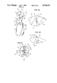
- FIG. 1 is a side view of a drill bit embodiment of this invention
- FIG. 3 is a sectional view taken along section line III--III of FIG. 1;
- FIG. 4 is a perspective view showing how a hard tip is installed in a groove formed in the cutting end of the drill bit shown in FIG. 1;
- FIG. 5 is a front view for explaining a thinning treatment applied to the embodiment shown in FIG. 1;
- FIG. 6 is a cutting end view looking at the front end of the drill bit shown in FIG. 1;
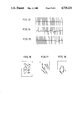
- FIGS. 7 and 8 are cutting end views looking at the front ends of drill bit structures used for Comparative Examples 1 and 2, the views corresponding to that of FIG. 6;
- FIG. 9 shows performance characteristics of the drill bit of the invention shown in FIG. 6 compared to the respective characteristics of conventional drill bits shown in FIGS. 7 and 8;
- FIG. 10 is an end view of the present drill bit for explaining the chip ejection associated with the end configuration shown in FIG. 6, but showing the drill bit structure in a drilling operation;
- FIGS. 11 and 12 are views, corresponding to FIG. 10, of the cutting ends of the drill bit structures of Comparative Examples 1 and 2 shown in FIGS. 7 and 8, again showing the drill bits in operation;
- FIG. 13 is a view for explaining the accuracy of the drilled surface of a sample drilled by using the present drill bit embodiment shown in FIG. 1;
- FIGS. 14 and 15 are views showing the accuracy of the drilled surfaces of samples drilled by using the drill bit structures of Comparative Examples 1 and 2 shown in FIGS. 7 and 8, the views corresponding to that of FIG. 13;
- FIG. 16 is a view showing chips produced by a drilling operation using the embodiment shown in FIG. 1;
- FIGS. 17 and 18 are views showing chips produced by drilling operations using the drill bit structures of the Comparative Examples 1 and 2 shown in FIGS. 7 and 8;
- FIG. 19 is an enlarged side view of a portion of the drill bit cutting end taken in the direction of arrow A in FIG. 5;
- a hard tip 9 is fitted in the groove 7 and fixed therein as by soldering.
- the cutting lips 10 are formed by this hard tip 9, with the result that a balanced symmetry with respect to the center of rotation of the drill bit during a drilling operation is reliably and easily attained.
- the shank 2 and drill bit body 4 may be made of high speed steel, for example.
- the hard tip 9 may be made of a cemented carbide alloy, high speed steel, cubic boron nitride sintered compact (CBN sintered compact) or other hard material.
- CBN sintered compact cubic boron nitride sintered compact
- a hard tip 9 made of cemented carbide alloys is used and its surface is coated with TiC, TiCN, TiN or Al 2 O 3 .
- oil passages 8a, 8b extend from the front end of the cutting portion 6 to the base end of the shank 2.
- the hard tip 9 has a thickness, or length along the axis of the drill body 4, equal to at least the web thickness of the front end of the drill bit body 4 and is so formed as to serve as curved chip breaker.
- the web thickness is 25-35% of the drill bit diameter
- the flute width ratio is 0.4:1 to 0.8:1
- the web thickness of diameter is shown by the inner circle in FIG. 5.
- the cutting lips of the hard tip 9 have been subjected to thinning, thereby forming portions 11 shown by hatched regions in FIG. 5 providing a width of a chisel 12 in the range of 0-0.4 mm, cutting lips 21 formed at the end of the web corresponding to chisel lips which are substantially straight, and an angle ⁇ 1 between the cutting lip 21 and the peripheral cutting lip 10 in the range of 35° to 45°.
- a connecting or transition portion 22 between the cutting lip 21 of the web and the outer cutting lip 10 is so formed as to describe a convex arc with respect to the direction of rotation of the drill bit structure 1.
- a lateral wall portion 13 unconnected to the cutting lip 10 is formed on the drill bit body 4 so that it is curved, as shown in FIG. 5 for causing chips to finely curl, with the consequent smooth ejection of chips.
- the thickness of the hard tip 9, e.g. its length axially of the drill bit structure, is greater than at least the web thickness.
- the thickness of the hard tip 9 is greater than at least the web thickness.
- the web thickness is set in the range of 25-35% of the drill bit diameter. This feature provides the required rigidity. It has been found that setting the web thickness to less than 25% would result in an insufficient rigidity while setting it at more than 35% would result in a reduced chip ejection capability.
- each outer cutting lip 10 as seen in the end view, measured at positions spaced at least 2/3 of the drill diameter outwardly from the drill center, is negative, this would result in an increase in the cutting resistance and a decrease in rigidity.
- the positive rake angle is increased, the strength of the outer peripheral portion of the cutting lip 10 would decrease.
- this invention specifies that the aforesaid radial rake angle be in the range of -5° to positive values, preferably in the range of 0° to +10°.
- the cutting lip 10 is given a concavely arcuate form so that the rake angle in the outer peripheral region is in the range of -5° to positive values, as shown in FIG. 5, the production of chips will be shared by the longer portion of the cutting lip 10. Therefore, in the case of the cutting lip 10 of this embodiment, as compared with a straight cutting edge, chips can be smoothly ejected and the cutting chip 10 is lengthened, so that work to be done per unit length of the cutting lip is decreased, leading to an increase in wear resistance.
- the connecting portion 22 between the cutting lip 21 of the web portion and the outer cutting lip 10 defines a convex arc with respect to the direction of rotation of the drill bit structure 1. Therefore, vibrations occurring during drilling are reduced and chips tend to curl more easily, so that the ejection of chips is promoted.
- the axial rake angle ⁇ 2 of the rake surface 23 of the web portion formed by thinning is set in the range of -5° to +5°.
- the axial length of the rake surface 23 is 0 mm at the drill axis position.
- the intersection line 25 between the rake surface 23 and the adjacent ground surface 24 formed simultaneously with the rake surface 23 has an angle of inclination ⁇ 3 with the drill axis in the range of 25° to 60°. Therefore, the angle of inclination ⁇ 3 is such that the axial length of the rake surface 23 is sufficient to prevent chips being produced, from striking the adjacent ground surface 24 to increase thrust. Further, the angle ⁇ 3 makes sure that the chip breaking function and the strength of the drill bit structure are sufficient.
- the relative distance in Table 1 refers to a distance L from point P3 on the flute wall opposite to the cutting lip 10 to a line extending at a right angle to an imaginary reference line l connecting the point P1, which is at the outer peripheral end of the cutting lip 10, and point P2 on the cutting lip 10 spaced 2/3 of the radius from the central axis toward the outer periphery.
- Comparative example 1 is not generally used but was prepared as a model sample to represent a typical bit for comparison purposes.
- the diameter of each drill bit was 20 mm and the cutting tip material was cemented carbide alloy P30 plus a TiCN coating.
- each drill bit was as shown in FIG. 6 for the embodiment of the invention, in FIG. 7 for the comparative example 1, and FIG. 8 for the comparative example 2.
- the comparative example 1 had a high strength and in some respects provided data comparable to that of the embodiment, but was poor in chip disposal and its cutting resistance was so high that it broke.
- the embodiment and comparative examples 1 and 2 were tested for cutting resistance. The result was as shown in FIG. 9 in which the feed (mm/rev) is plotted on the horizontal axis and on the vertical axis are plotted thrust (Kg), torque (Kg ⁇ cm) and horse power (HP).
- the construction which makes the radial rake angle positive improves the sharpness of the drill bit, and the short, relative distance L ensures that a chip 14 curls in the hole 16 without abutting against the hole wall 15 and is discharged in the hole 16, as shown in FIG. 10 or discharged while being broken.
- the data on the finished surface roughness are as shown in FIGS. 13, 14 and 15, wherein the scale on the horizontal axis (depth) is magnified 10 times and the scale on the vertical axis (radial unevenness) is magnified 250 times.
- the finished surface obtained by the drill of the embodiment of this invention is very good.
- the chip 14 breaks into small pieces and curls and is discharged in the hole 16.
- the finished surface of the drilled hole is good without being roughened and there is no danger of making a hole in the flute wall 13.
- the allowance for the enlargement of drilled holes is much less in the drill bits of the embodiment of this invention than in the conventional drill bits. It is also seen that the variation of allowance is less, proving the superiority of the drill bits of this invention.
- the overall ratings of the respective drill bits are as shown in Table 6.
- the mark X means "undesirable,” the mark ⁇ means “desirable,” and the mark ⁇ means "superior”.
- the drill bit of this embodiment is the best of all, next comes the heretofore actually used drill bit of the comparative example 2, and the worst is the drill bit of the comparative example 1 produced merely as a model.
Landscapes
- Engineering & Computer Science (AREA)
- Mechanical Engineering (AREA)
- Drilling Tools (AREA)
Applications Claiming Priority (2)
| Application Number | Priority Date | Filing Date | Title |
|---|---|---|---|
| JP1984034145U JPS60146605U (ja) | 1984-03-12 | 1984-03-12 | ドリル構造 |
| JP59-34145 | 1984-03-12 |
Publications (1)
| Publication Number | Publication Date |
|---|---|
| US4728231A true US4728231A (en) | 1988-03-01 |
Family
ID=12406034
Family Applications (1)
| Application Number | Title | Priority Date | Filing Date |
|---|---|---|---|
| US06/707,970 Expired - Lifetime US4728231A (en) | 1984-03-12 | 1985-03-04 | Drill bit structure |
Country Status (8)
| Country | Link |
|---|---|
| US (1) | US4728231A (es) |
| EP (1) | EP0158820B2 (es) |
| JP (1) | JPS60146605U (es) |
| KR (1) | KR880000678Y1 (es) |
| AU (1) | AU566144B2 (es) |
| DE (1) | DE3563423D1 (es) |
| ES (1) | ES8602462A1 (es) |
| ZA (1) | ZA851837B (es) |
Cited By (53)
| Publication number | Priority date | Publication date | Assignee | Title |
|---|---|---|---|---|
| US5065647A (en) * | 1990-08-27 | 1991-11-19 | Ford Motor Company | Bit for drilling cast iron |
| US5895179A (en) * | 1997-05-16 | 1999-04-20 | Hilti Aktiengesellschaft | Drill |
| US5904455A (en) * | 1994-10-07 | 1999-05-18 | Kennametal Hertel Ag | Drill with a drill point part |
| US5947660A (en) * | 1995-05-04 | 1999-09-07 | Seco Tools Ab | Tool for cutting machining |
| US6012881A (en) * | 1995-03-03 | 2000-01-11 | Komet Praezisionswerkzeuge Robert Breuning Gmbh | Drilling tool |
| WO2000003825A1 (en) * | 1998-07-15 | 2000-01-27 | Colvin Kevin F | Cutting tool point |
| US6071046A (en) * | 1998-03-27 | 2000-06-06 | Iscar, Ltd. | Drill |
| WO2001045885A1 (en) * | 1999-12-21 | 2001-06-28 | Sandvik Aktiebolag | Tool tip and tool body assembly |
| WO2001068303A1 (en) * | 2000-03-17 | 2001-09-20 | Sandvik Aktiebolag | Drilling tool |
| US6685402B2 (en) | 2001-03-27 | 2004-02-03 | Allied Machine & Engineering Corp. | Drill insert geometry having V-notched web |
| WO2004014241A1 (en) * | 2002-08-08 | 2004-02-19 | Liam Patrick Ellis | A drill bit and method for producing a drill bit |
| US6719501B2 (en) * | 2000-10-27 | 2004-04-13 | Nachi-Fujikoshi Corp. | Cemented carbide end mill |
| US20040096281A1 (en) * | 2002-09-18 | 2004-05-20 | Sherman Michael M. | Air cooled router bit |
| US20040223823A1 (en) * | 2001-03-27 | 2004-11-11 | Allied Machine & Engineering Corp. | Drill insert geometry having V-notched web |
| US20060039767A1 (en) * | 2004-08-23 | 2006-02-23 | Osg Corporation | Carbide drill capable of drilling hole with reduced degree of work hardening |
| US20060159532A1 (en) * | 2003-04-01 | 2006-07-20 | Juergen Heilmann | Tool for machine tools |
| US20070036622A1 (en) * | 2005-08-12 | 2007-02-15 | Yg-1 Co., Ltd. | Spade drill insert |
| US20070160436A1 (en) * | 2003-08-28 | 2007-07-12 | Vijitha Weerasunghe | Coated bore cutting tools |
| US20070274794A1 (en) * | 2006-05-26 | 2007-11-29 | Cirino Thomas J | Oblique angle serration location and drive interface |
| US20080101878A1 (en) * | 2006-10-26 | 2008-05-01 | Seco Tools Ab | Tool for cutting machining |
| US20080131221A1 (en) * | 2006-12-04 | 2008-06-05 | Mitsubishi Materials Corporation | Drill |
| US20080166194A1 (en) * | 2007-01-09 | 2008-07-10 | Durfee Laverne R | Drill bit |
| US20090208300A1 (en) * | 2008-02-19 | 2009-08-20 | Irwin Industrial Tool Company | Self feed bit |
| US20100003094A1 (en) * | 2007-01-09 | 2010-01-07 | Irwin Industrial Tool Company | Drill bit |
| US20100122752A1 (en) * | 2008-11-17 | 2010-05-20 | Lee Valley Tools, Ltd. | Interlocking, adjustable edge-forming router bit |
| US20100307640A1 (en) * | 2009-06-03 | 2010-12-09 | Durfee La Verne R | Cutting edge and cutting tool |
| US20110135413A1 (en) * | 2008-05-30 | 2011-06-09 | Kennametal Inc. | Reamer |
| US20110208194A1 (en) * | 2009-08-20 | 2011-08-25 | Howmedica Osteonics Corp. | Flexible acl instrumentation, kit and method |
| US20110268518A1 (en) * | 2010-04-30 | 2011-11-03 | Karthik Sampath | Rotary cutting tool having pcd cutting tip |
| US8092126B2 (en) | 2005-03-29 | 2012-01-10 | Mitsubishi Materials Corporation | Indexable drill |
| CN104117700A (zh) * | 2013-04-25 | 2014-10-29 | 钴碳化钨硬质合金公司 | 混合型切削刀具、切屑传输部以及用于生产切削刀具的方法 |
| US20140341667A1 (en) * | 2011-09-16 | 2014-11-20 | Osg Corporation | Drill body of indexable drill |
| US20150080898A1 (en) * | 2009-05-08 | 2015-03-19 | DePuy Synthes Products, LLC | Disposable burr attachment |
| US9078740B2 (en) | 2013-01-21 | 2015-07-14 | Howmedica Osteonics Corp. | Instrumentation and method for positioning and securing a graft |
| US9643282B2 (en) | 2014-10-17 | 2017-05-09 | Kennametal Inc. | Micro end mill and method of manufacturing same |
| US9795398B2 (en) | 2011-04-13 | 2017-10-24 | Howmedica Osteonics Corp. | Flexible ACL instrumentation, kit and method |
| US9808242B2 (en) | 2012-04-06 | 2017-11-07 | Howmedica Osteonics Corp. | Knotless filament anchor for soft tissue repair |
| US9986992B2 (en) | 2014-10-28 | 2018-06-05 | Stryker Corporation | Suture anchor and associated methods of use |
| US10092300B2 (en) | 2009-05-08 | 2018-10-09 | DePuy Synthes Products, Inc. | Surgical drill with curved burr attachment and method |
| US10105769B2 (en) | 2014-04-17 | 2018-10-23 | Kennametal Inc. | Machining tool and method for manufacturing a machining tool |
| US10123792B2 (en) | 2012-08-03 | 2018-11-13 | Howmedica Osteonics Corp. | Soft tissue fixation devices and methods |
| AU2016244322B2 (en) * | 2002-08-08 | 2019-03-21 | Surgibit Ip Holdings Pty Ltd | A drill bit and method for producing a drill bit |
| US10285685B2 (en) | 2013-03-04 | 2019-05-14 | Howmedica Osteonics Corp. | Knotless filamentary fixation devices, assemblies and systems and methods of assembly and use |
| US10369636B2 (en) | 2014-04-17 | 2019-08-06 | Kennametal Inc. | Machining tool and method for manufacturing a machining tool |
| US10448944B2 (en) | 2011-11-23 | 2019-10-22 | Howmedica Osteonics Corp. | Filamentary fixation device |
| US10471522B2 (en) * | 2015-08-27 | 2019-11-12 | Mitsubishi Materials Corporation | Drill |
| US10532412B2 (en) | 2016-09-23 | 2020-01-14 | Milwaukee Electric Tool Corporation | Hole saw arbor assembly |
| US10610211B2 (en) | 2013-12-12 | 2020-04-07 | Howmedica Osteonics Corp. | Filament engagement system and methods of use |
| US10730119B2 (en) | 2017-01-06 | 2020-08-04 | Milwaukee Electric Tool Corporation | Hole saw |
| US11141801B2 (en) | 2014-04-23 | 2021-10-12 | Korloy Inc. | Cutting tool having partially-removed film formed thereon |
| US11331094B2 (en) | 2013-04-22 | 2022-05-17 | Stryker Corporation | Method and apparatus for attaching tissue to bone |
| US11376675B2 (en) | 2014-04-23 | 2022-07-05 | Korloy Inc. | Cutting tool having partially-removed film formed thereon |
| USD965653S1 (en) | 2017-08-15 | 2022-10-04 | Milwaukee Electric Tool Corporation | Hole saw |
Families Citing this family (8)
| Publication number | Priority date | Publication date | Assignee | Title |
|---|---|---|---|---|
| US5230593A (en) * | 1987-12-14 | 1993-07-27 | Mitsubishi Kinzoku Kabushiki Kaisha | Twist drill |
| US4983079A (en) * | 1987-12-14 | 1991-01-08 | Mitsubishi Kinzoku Kabushiki Kaisha | Twist drill |
| ATE134325T1 (de) * | 1990-11-26 | 1996-03-15 | De Beers Ind Diamond | Schneideinsatz für ein rotierendes schneidwerkzeug |
| EP0701497B1 (de) * | 1993-06-08 | 1998-02-11 | KIPPE, Michael | Spanabhebendes werkzeug, insbesondere bohr- oder fräswerkzeug |
| DE10361065A1 (de) * | 2003-12-23 | 2005-07-28 | Robert Bosch Gmbh | Mehrzweckbohrwerkzeug |
| JP4757304B2 (ja) | 2005-07-05 | 2011-08-24 | ゲッチ ルイギ | チャック及び回転式方向合わせ装置 |
| DE102006020538A1 (de) * | 2006-05-03 | 2007-11-15 | Irwin Industrial Tools Gmbh | Bohrkopf für Bohrwerkzeug und Bohrwerkzeug |
| DE102008027705A1 (de) | 2008-06-11 | 2009-12-17 | Gühring Ohg | Mehrschneidiges Bohrwerkzeug zur Zerspannung von schwer zerspanbaren, insbesondere langspanenden Werkstoffen |
Citations (17)
| Publication number | Priority date | Publication date | Assignee | Title |
|---|---|---|---|---|
| US1407546A (en) * | 1919-10-15 | 1922-02-21 | Joseph Felix Alexander | Twist drill |
| US1887374A (en) * | 1929-04-10 | 1932-11-08 | Cleveland Twist Drill Co | Drill |
| US1887372A (en) * | 1928-12-22 | 1932-11-08 | Cleveland Twist Drill Co | Cutting and forming tools, implements, and the like |
| DE594043C (de) * | 1930-05-27 | 1934-03-09 | Fried Krupp Akt Ges | Verbindung hochschnitthaltiger Werkstoffe mit hochlegiertem Stahl (Schnellstahl) durch Loetung mittels einer Zwischenlage |
| FR887811A (fr) * | 1941-12-12 | 1943-11-24 | Foret ou autre outil rotatif, à mise rapportée | |
| US2555302A (en) * | 1947-08-25 | 1951-06-05 | Floyd F Cogsdill | Twist drill |
| FR1068867A (fr) * | 1952-09-17 | 1954-07-01 | Perfectionnements dans la fabrication des forets hélicoïdaux | |
| US2778252A (en) * | 1956-09-26 | 1957-01-22 | Nat Twist Drill & Tool Company | Self-thinned heavy-duty twist drill structure |
| FR1190274A (fr) * | 1958-01-20 | 1959-10-12 | Procédé pour la déternination du profil de l'arête coupante d'un foret | |
| US3014386A (en) * | 1957-09-03 | 1961-12-26 | United Greenfield Corp | Drill |
| US3564947A (en) * | 1968-05-17 | 1971-02-23 | Karl Stephan Maier | Twist drilis |
| JPS5444293A (en) * | 1977-09-13 | 1979-04-07 | Sumitomo Electric Ind Ltd | Composite cutting tool and method of regenerating the same |
| US4160616A (en) * | 1977-10-03 | 1979-07-10 | Winblad Michael E | Drill containing minimum cutting material |
| JPS5585653A (en) * | 1978-12-21 | 1980-06-27 | Ngk Spark Plug Co Ltd | Ceramic sintered body for cutting tool |
| DE8203911U1 (de) * | 1982-02-12 | 1982-08-19 | Hermann Bilz Gmbh & Co, 7300 Esslingen | Bohrwerkzeug |
| DE3205051A1 (de) * | 1982-02-12 | 1983-08-25 | Hermann Bilz Gmbh & Co, 7300 Esslingen | Bohrwerkzeug |
| EP0127009A1 (en) * | 1983-05-25 | 1984-12-05 | Sumitomo Electric Industries Limited | Drill |
-
1984
- 1984-03-12 JP JP1984034145U patent/JPS60146605U/ja active Pending
-
1985
- 1985-02-11 KR KR2019850001435U patent/KR880000678Y1/ko not_active IP Right Cessation
- 1985-03-04 US US06/707,970 patent/US4728231A/en not_active Expired - Lifetime
- 1985-03-07 AU AU39639/85A patent/AU566144B2/en not_active Ceased
- 1985-03-08 ES ES541117A patent/ES8602462A1/es not_active Expired
- 1985-03-11 DE DE8585102757T patent/DE3563423D1/de not_active Expired
- 1985-03-11 EP EP85102757A patent/EP0158820B2/en not_active Expired - Lifetime
- 1985-03-12 ZA ZA851837A patent/ZA851837B/xx unknown
Patent Citations (18)
| Publication number | Priority date | Publication date | Assignee | Title |
|---|---|---|---|---|
| US1407546A (en) * | 1919-10-15 | 1922-02-21 | Joseph Felix Alexander | Twist drill |
| US1887372A (en) * | 1928-12-22 | 1932-11-08 | Cleveland Twist Drill Co | Cutting and forming tools, implements, and the like |
| US1887374A (en) * | 1929-04-10 | 1932-11-08 | Cleveland Twist Drill Co | Drill |
| DE594043C (de) * | 1930-05-27 | 1934-03-09 | Fried Krupp Akt Ges | Verbindung hochschnitthaltiger Werkstoffe mit hochlegiertem Stahl (Schnellstahl) durch Loetung mittels einer Zwischenlage |
| FR887811A (fr) * | 1941-12-12 | 1943-11-24 | Foret ou autre outil rotatif, à mise rapportée | |
| US2555302A (en) * | 1947-08-25 | 1951-06-05 | Floyd F Cogsdill | Twist drill |
| FR1068867A (fr) * | 1952-09-17 | 1954-07-01 | Perfectionnements dans la fabrication des forets hélicoïdaux | |
| US2778252A (en) * | 1956-09-26 | 1957-01-22 | Nat Twist Drill & Tool Company | Self-thinned heavy-duty twist drill structure |
| US3014386A (en) * | 1957-09-03 | 1961-12-26 | United Greenfield Corp | Drill |
| FR1190274A (fr) * | 1958-01-20 | 1959-10-12 | Procédé pour la déternination du profil de l'arête coupante d'un foret | |
| US3564947A (en) * | 1968-05-17 | 1971-02-23 | Karl Stephan Maier | Twist drilis |
| JPS5444293A (en) * | 1977-09-13 | 1979-04-07 | Sumitomo Electric Ind Ltd | Composite cutting tool and method of regenerating the same |
| US4160616A (en) * | 1977-10-03 | 1979-07-10 | Winblad Michael E | Drill containing minimum cutting material |
| JPS5585653A (en) * | 1978-12-21 | 1980-06-27 | Ngk Spark Plug Co Ltd | Ceramic sintered body for cutting tool |
| DE8203911U1 (de) * | 1982-02-12 | 1982-08-19 | Hermann Bilz Gmbh & Co, 7300 Esslingen | Bohrwerkzeug |
| DE3205051A1 (de) * | 1982-02-12 | 1983-08-25 | Hermann Bilz Gmbh & Co, 7300 Esslingen | Bohrwerkzeug |
| EP0127009A1 (en) * | 1983-05-25 | 1984-12-05 | Sumitomo Electric Industries Limited | Drill |
| US4583888A (en) * | 1983-05-25 | 1986-04-22 | Sumitomo Electric Industries, Ltd. | Cemented carbide drill bit |
Non-Patent Citations (2)
| Title |
|---|
| Machines Production, No. 365, Nov. 18, 1983, pp. 37 39, Sofetec, Boulogne, France. * |
| Machines Production, No. 365, Nov. 18, 1983, pp. 37-39, Sofetec, Boulogne, France. |
Cited By (91)
| Publication number | Priority date | Publication date | Assignee | Title |
|---|---|---|---|---|
| US5065647A (en) * | 1990-08-27 | 1991-11-19 | Ford Motor Company | Bit for drilling cast iron |
| US5904455A (en) * | 1994-10-07 | 1999-05-18 | Kennametal Hertel Ag | Drill with a drill point part |
| US6012881A (en) * | 1995-03-03 | 2000-01-11 | Komet Praezisionswerkzeuge Robert Breuning Gmbh | Drilling tool |
| US5947660A (en) * | 1995-05-04 | 1999-09-07 | Seco Tools Ab | Tool for cutting machining |
| US6183688B1 (en) | 1995-05-04 | 2001-02-06 | Seco Tools Ab | Tool for cutting machining |
| US5895179A (en) * | 1997-05-16 | 1999-04-20 | Hilti Aktiengesellschaft | Drill |
| US6071046A (en) * | 1998-03-27 | 2000-06-06 | Iscar, Ltd. | Drill |
| US6056486A (en) * | 1998-07-15 | 2000-05-02 | Colvin; Kevin F. | Cutting tool point |
| US6270298B1 (en) | 1998-07-15 | 2001-08-07 | Kevin F. Colvin | Cutting tool point |
| WO2000003825A1 (en) * | 1998-07-15 | 2000-01-27 | Colvin Kevin F | Cutting tool point |
| WO2001045885A1 (en) * | 1999-12-21 | 2001-06-28 | Sandvik Aktiebolag | Tool tip and tool body assembly |
| WO2001068303A1 (en) * | 2000-03-17 | 2001-09-20 | Sandvik Aktiebolag | Drilling tool |
| EP1136161A1 (en) * | 2000-03-17 | 2001-09-26 | Sandvik Aktiebolag | Drilling tool |
| US6481938B2 (en) | 2000-03-17 | 2002-11-19 | Sandvik Ab | Drilling tool including a shank and a cutting body detachably secured thereto |
| US6719501B2 (en) * | 2000-10-27 | 2004-04-13 | Nachi-Fujikoshi Corp. | Cemented carbide end mill |
| US6685402B2 (en) | 2001-03-27 | 2004-02-03 | Allied Machine & Engineering Corp. | Drill insert geometry having V-notched web |
| US20060147285A1 (en) * | 2001-03-27 | 2006-07-06 | Allied Machine & Enginnering Corp. | Drill Insert Geometry having V-Notched Web |
| US7371035B2 (en) | 2001-03-27 | 2008-05-13 | Allied Machine & Engineering Corp. | Drill insert geometry having V-notched web |
| US20040179913A1 (en) * | 2001-03-27 | 2004-09-16 | Allied Machine & Engineering Corp. | Drill insert geometry having V-notched web |
| US20040223823A1 (en) * | 2001-03-27 | 2004-11-11 | Allied Machine & Engineering Corp. | Drill insert geometry having V-notched web |
| US7114893B2 (en) | 2001-03-27 | 2006-10-03 | Allied Machine & Engineering Corp. | Drill insert geometry having V-notched web |
| US6986628B2 (en) | 2001-03-27 | 2006-01-17 | Allied Machine & Engineering Corp. | Drill insert geometry having V-notched web |
| AU2016244322B2 (en) * | 2002-08-08 | 2019-03-21 | Surgibit Ip Holdings Pty Ltd | A drill bit and method for producing a drill bit |
| WO2004014241A1 (en) * | 2002-08-08 | 2004-02-19 | Liam Patrick Ellis | A drill bit and method for producing a drill bit |
| US11337709B2 (en) | 2002-08-08 | 2022-05-24 | Surgibit Ip Holdings Pty Limited | Drill bit and method for producing a drill bit |
| US20050203526A1 (en) * | 2002-08-08 | 2005-09-15 | Ellis Liam P. | Drill bit and method for producing a drill bit |
| US7892235B2 (en) | 2002-08-08 | 2011-02-22 | Surgibit Ip Holdings Pty Limited | Drill bit and method for producing a drill bit |
| US7036539B2 (en) * | 2002-09-18 | 2006-05-02 | Black & Decker Inc. | Air cooled router bit |
| US20040096281A1 (en) * | 2002-09-18 | 2004-05-20 | Sherman Michael M. | Air cooled router bit |
| US20060159532A1 (en) * | 2003-04-01 | 2006-07-20 | Juergen Heilmann | Tool for machine tools |
| US7556458B2 (en) * | 2003-04-01 | 2009-07-07 | Komet Group Holding Gmbh | Tool for machine tools |
| US20070160436A1 (en) * | 2003-08-28 | 2007-07-12 | Vijitha Weerasunghe | Coated bore cutting tools |
| US7922428B2 (en) * | 2003-08-28 | 2011-04-12 | Dormer Tools Limited | Coated bore cutting tools |
| US20060039767A1 (en) * | 2004-08-23 | 2006-02-23 | Osg Corporation | Carbide drill capable of drilling hole with reduced degree of work hardening |
| US8092126B2 (en) | 2005-03-29 | 2012-01-10 | Mitsubishi Materials Corporation | Indexable drill |
| US20070036622A1 (en) * | 2005-08-12 | 2007-02-15 | Yg-1 Co., Ltd. | Spade drill insert |
| US20070274794A1 (en) * | 2006-05-26 | 2007-11-29 | Cirino Thomas J | Oblique angle serration location and drive interface |
| US20080101878A1 (en) * | 2006-10-26 | 2008-05-01 | Seco Tools Ab | Tool for cutting machining |
| US20080131221A1 (en) * | 2006-12-04 | 2008-06-05 | Mitsubishi Materials Corporation | Drill |
| US7762748B2 (en) * | 2006-12-04 | 2010-07-27 | Mitsubishi Materials Corporation | Drill |
| US20080166194A1 (en) * | 2007-01-09 | 2008-07-10 | Durfee Laverne R | Drill bit |
| US20100003094A1 (en) * | 2007-01-09 | 2010-01-07 | Irwin Industrial Tool Company | Drill bit |
| US20090208300A1 (en) * | 2008-02-19 | 2009-08-20 | Irwin Industrial Tool Company | Self feed bit |
| US8070397B2 (en) | 2008-02-19 | 2011-12-06 | Irwin Industrial Tool Company | Self feed bit |
| US20110135413A1 (en) * | 2008-05-30 | 2011-06-09 | Kennametal Inc. | Reamer |
| US8708618B2 (en) * | 2008-05-30 | 2014-04-29 | Kennametal Inc. | Reamer |
| US8235080B2 (en) * | 2008-11-17 | 2012-08-07 | Lee Valley Tools, Ltd. | Interlocking, adjustable edge-forming router bit |
| US20100122752A1 (en) * | 2008-11-17 | 2010-05-20 | Lee Valley Tools, Ltd. | Interlocking, adjustable edge-forming router bit |
| US9907559B2 (en) * | 2009-05-08 | 2018-03-06 | DePuy Synthes Products, Inc. | Disposable burr attachment |
| US11083469B2 (en) | 2009-05-08 | 2021-08-10 | DePuy Synthes Products, Inc. | Surgical drill with curved burr attachment and method |
| US10842508B2 (en) | 2009-05-08 | 2020-11-24 | DePuy Synthes Products, Inc. | Disposable burr attachment |
| US20150080898A1 (en) * | 2009-05-08 | 2015-03-19 | DePuy Synthes Products, LLC | Disposable burr attachment |
| US10092300B2 (en) | 2009-05-08 | 2018-10-09 | DePuy Synthes Products, Inc. | Surgical drill with curved burr attachment and method |
| US20100307640A1 (en) * | 2009-06-03 | 2010-12-09 | Durfee La Verne R | Cutting edge and cutting tool |
| US20110208194A1 (en) * | 2009-08-20 | 2011-08-25 | Howmedica Osteonics Corp. | Flexible acl instrumentation, kit and method |
| US10231744B2 (en) | 2009-08-20 | 2019-03-19 | Howmedica Osteonics Corp. | Flexible ACL instrumentation, kit and method |
| US11364041B2 (en) | 2009-08-20 | 2022-06-21 | Howmedica Osteonics Corp. | Flexible ACL instrumentation, kit and method |
| US9232954B2 (en) | 2009-08-20 | 2016-01-12 | Howmedica Osteonics Corp. | Flexible ACL instrumentation, kit and method |
| US10238404B2 (en) | 2009-08-20 | 2019-03-26 | Howmedica Osteonics Corp. | Flexible ACL instrumentation, kit and method |
| US9539652B2 (en) * | 2010-04-30 | 2017-01-10 | Kennametal Inc. | Rotary cutting tool having PCD cutting tip |
| US20110268518A1 (en) * | 2010-04-30 | 2011-11-03 | Karthik Sampath | Rotary cutting tool having pcd cutting tip |
| US10328536B2 (en) | 2010-04-30 | 2019-06-25 | Kennametal Inc. | Rotary cutting tool having PCD cutting tip |
| US9795398B2 (en) | 2011-04-13 | 2017-10-24 | Howmedica Osteonics Corp. | Flexible ACL instrumentation, kit and method |
| US9446457B2 (en) * | 2011-09-16 | 2016-09-20 | Osg Corporation | Drill body of indexable drill |
| US20140341667A1 (en) * | 2011-09-16 | 2014-11-20 | Osg Corporation | Drill body of indexable drill |
| US11844508B2 (en) | 2011-11-23 | 2023-12-19 | Howmedica Osteonics Corp. | Filamentary fixation device |
| US10448944B2 (en) | 2011-11-23 | 2019-10-22 | Howmedica Osteonics Corp. | Filamentary fixation device |
| US11076865B2 (en) | 2012-04-06 | 2021-08-03 | Howmedica Osteonics Corp. | Knotless filament anchor for soft tissue repair |
| US9808242B2 (en) | 2012-04-06 | 2017-11-07 | Howmedica Osteonics Corp. | Knotless filament anchor for soft tissue repair |
| US10123792B2 (en) | 2012-08-03 | 2018-11-13 | Howmedica Osteonics Corp. | Soft tissue fixation devices and methods |
| US10653410B2 (en) | 2012-08-03 | 2020-05-19 | Howmedica Osteonics Corp. | Soft tissue fixation devices and methods |
| US9078740B2 (en) | 2013-01-21 | 2015-07-14 | Howmedica Osteonics Corp. | Instrumentation and method for positioning and securing a graft |
| US10285685B2 (en) | 2013-03-04 | 2019-05-14 | Howmedica Osteonics Corp. | Knotless filamentary fixation devices, assemblies and systems and methods of assembly and use |
| US11331094B2 (en) | 2013-04-22 | 2022-05-17 | Stryker Corporation | Method and apparatus for attaching tissue to bone |
| US20140321931A1 (en) * | 2013-04-25 | 2014-10-30 | Kennametal Inc. | Hybrid cutting tool, chip transporting portion and process for producing a cutting tool |
| CN104117700A (zh) * | 2013-04-25 | 2014-10-29 | 钴碳化钨硬质合金公司 | 混合型切削刀具、切屑传输部以及用于生产切削刀具的方法 |
| US10610211B2 (en) | 2013-12-12 | 2020-04-07 | Howmedica Osteonics Corp. | Filament engagement system and methods of use |
| US10369636B2 (en) | 2014-04-17 | 2019-08-06 | Kennametal Inc. | Machining tool and method for manufacturing a machining tool |
| US10105769B2 (en) | 2014-04-17 | 2018-10-23 | Kennametal Inc. | Machining tool and method for manufacturing a machining tool |
| US11141801B2 (en) | 2014-04-23 | 2021-10-12 | Korloy Inc. | Cutting tool having partially-removed film formed thereon |
| US11376675B2 (en) | 2014-04-23 | 2022-07-05 | Korloy Inc. | Cutting tool having partially-removed film formed thereon |
| US9643282B2 (en) | 2014-10-17 | 2017-05-09 | Kennametal Inc. | Micro end mill and method of manufacturing same |
| US11006945B2 (en) | 2014-10-28 | 2021-05-18 | Stryker Corporation | Suture anchor and associated methods of use |
| US9986992B2 (en) | 2014-10-28 | 2018-06-05 | Stryker Corporation | Suture anchor and associated methods of use |
| US10471522B2 (en) * | 2015-08-27 | 2019-11-12 | Mitsubishi Materials Corporation | Drill |
| US10532412B2 (en) | 2016-09-23 | 2020-01-14 | Milwaukee Electric Tool Corporation | Hole saw arbor assembly |
| US11154940B2 (en) | 2016-09-23 | 2021-10-26 | Milwaukee Electric Tool Corporation | Hole saw arbor assembly |
| US11559840B2 (en) | 2017-01-06 | 2023-01-24 | Milwaukee Electric Tool Corporation | Hole saw |
| US10730119B2 (en) | 2017-01-06 | 2020-08-04 | Milwaukee Electric Tool Corporation | Hole saw |
| USD965653S1 (en) | 2017-08-15 | 2022-10-04 | Milwaukee Electric Tool Corporation | Hole saw |
| USD973733S1 (en) | 2017-08-15 | 2022-12-27 | Milwaukee Electric Tool Corporation | Hole saw |
Also Published As
| Publication number | Publication date |
|---|---|
| ES541117A0 (es) | 1985-12-01 |
| AU566144B2 (en) | 1987-10-08 |
| JPS60146605U (ja) | 1985-09-28 |
| EP0158820B1 (en) | 1988-06-22 |
| EP0158820A1 (en) | 1985-10-23 |
| KR880000678Y1 (ko) | 1988-03-15 |
| ZA851837B (en) | 1985-11-27 |
| KR850009757U (ko) | 1985-12-05 |
| EP0158820B2 (en) | 1997-03-19 |
| AU3963985A (en) | 1985-09-19 |
| DE3563423D1 (en) | 1988-07-28 |
| ES8602462A1 (es) | 1985-12-01 |
Similar Documents
| Publication | Publication Date | Title |
|---|---|---|
| US4728231A (en) | Drill bit structure | |
| US4583888A (en) | Cemented carbide drill bit | |
| US5350261A (en) | Twist drill | |
| US4744705A (en) | Twist drill bit | |
| EP1280625B1 (en) | Drill with improved cutting insert formation | |
| US5322394A (en) | Highly stiff end mill | |
| JPS62188616A (ja) | フライス | |
| JPH08155713A (ja) | ツイストドリル | |
| JPS625726B2 (es) | ||
| JPS61270010A (ja) | 穴あけ工具 | |
| JPS6389211A (ja) | ツイストドリル | |
| JPS6260202B2 (es) | ||
| JP3318020B2 (ja) | ボールエンドミル | |
| JPH0569214A (ja) | 穴あけ工具 | |
| JP2538864Y2 (ja) | 難削材用硬質膜被覆ドリル | |
| JPH05261612A (ja) | ドリル | |
| JPH0532164B2 (es) | ||
| JP2623304B2 (ja) | サーメット製ツイストドリル | |
| JP2003136319A (ja) | 刃先交換式ツイストドリル | |
| JP2535644Y2 (ja) | ドリル | |
| JPS6246492Y2 (es) | ||
| JPS6246491Y2 (es) | ||
| JPS5835366Y2 (ja) | 回転切削工具 | |
| JPH069813U (ja) | ドリル | |
| JP2533255Y2 (ja) | ドリル |
Legal Events
| Date | Code | Title | Description |
|---|---|---|---|
| AS | Assignment |
Owner name: SUMITOMO ELECTRIC INDUSTRIES, LTD., 15 KITAHAMA 5- Free format text: ASSIGNMENT OF ASSIGNORS INTEREST.;ASSIGNORS:KUNIMORI, NAGATOSHI;MORI, YOSHIKATSU;JINDAI, MASAAKI;REEL/FRAME:004598/0869 Effective date: 19850213 Owner name: SUMITOMO ELECTRIC INDUSTRIES, LTD.,JAPAN Free format text: ASSIGNMENT OF ASSIGNORS INTEREST;ASSIGNORS:KUNIMORI, NAGATOSHI;MORI, YOSHIKATSU;JINDAI, MASAAKI;REEL/FRAME:004598/0869 Effective date: 19850213 |
|
| STCF | Information on status: patent grant |
Free format text: PATENTED CASE |
|
| FEPP | Fee payment procedure |
Free format text: PAYOR NUMBER ASSIGNED (ORIGINAL EVENT CODE: ASPN); ENTITY STATUS OF PATENT OWNER: LARGE ENTITY |
|
| FPAY | Fee payment |
Year of fee payment: 4 |
|
| SULP | Surcharge for late payment | ||
| FPAY | Fee payment |
Year of fee payment: 8 |
|
| FPAY | Fee payment |
Year of fee payment: 12 |