US4724774A - Safe-deposit installation - Google Patents

Safe-deposit installation Download PDF

Info

Publication number
US4724774A
US4724774A US06/936,458 US93645886A US4724774A US 4724774 A US4724774 A US 4724774A US 93645886 A US93645886 A US 93645886A US 4724774 A US4724774 A US 4724774A
Authority
US
United States
Prior art keywords
racks
safe
deposit
hoist mechanism
vault
Prior art date
Legal status (The legal status is an assumption and is not a legal conclusion. Google has not performed a legal analysis and makes no representation as to the accuracy of the status listed.)
Expired - Fee Related
Application number
US06/936,458
Inventor
Hans Wiedemar
Daniel Wiedemar
Current Assignee (The listed assignees may be inaccurate. Google has not performed a legal analysis and makes no representation or warranty as to the accuracy of the list.)
VIDMAR AG
Original Assignee
VIDMAR AG
Priority date (The priority date is an assumption and is not a legal conclusion. Google has not performed a legal analysis and makes no representation as to the accuracy of the date listed.)
Filing date
Publication date
Application filed by VIDMAR AG filed Critical VIDMAR AG
Assigned to VIDMAR AG reassignment VIDMAR AG ASSIGNMENT OF ASSIGNORS INTEREST. Assignors: WIEDEMAR, DANIEL, WIEDEMAR, HANS
Application granted granted Critical
Publication of US4724774A publication Critical patent/US4724774A/en
Anticipated expiration legal-status Critical
Expired - Fee Related legal-status Critical Current

Links

Images

Classifications

    • EFIXED CONSTRUCTIONS
    • E05LOCKS; KEYS; WINDOW OR DOOR FITTINGS; SAFES
    • E05GSAFES OR STRONG-ROOMS FOR VALUABLES; BANK PROTECTION DEVICES; SAFETY TRANSACTION PARTITIONS
    • E05G1/00Safes or strong-rooms for valuables
    • E05G1/06Safes or strong-rooms for valuables having provision for multiple compartments

Abstract

Within a vault (11) having an access aperture (12), a number of rectangular racks (1, 2) are individually and detachably mounted on an annular turntable (14) rotating in a horizontal plane. Each rack accommodates in compartments (6) of variable sizes a single row of individually accessible, superposed safe-deposit boxes (4), all the compartments of any one rack opening out on the same side of that rack. Within the turntable is a vertical hoist mechanism (7) comprising an upright (8) and a horizontal lifting arm (9) travelling along the upright. A selected rack (1a) is moved into a starting position by the turntable, seized by the lifting arm, and raised to the level of the access aperture independently of the other racks. There is no possibility of breaking through laterally from a safe-deposit box of any one rack into a safe-deposit box of another rack.

Description

This invention relates to facilities for the safekeeping of valuables, and more particularly to a safe-deposit installation of the type having a plurality of individually accessible safe-deposit boxes disposed one above the other in a number of rectangular racks in such a way that their access openings are all situated on one side of each rack, and a safe surrounding the racks at least partially and having at least one service opening.
Such safe-deposit installations are used particularly in banks but can also be used wherever valuables are to be deposited, e.g., in railroad stations, at airports, in hotels, etc.
An automated banking system is described in European Patent Application Publication No. 51,048. The safe-deposit installation of the system consists of a strongbox assembly rotating about a vertical axis. The strongboxes are so disposed that their entries are situated at the periphery of the arrangement. The strongbox assembly is accommodated in a cell, one wall of which has a large, vertical aperture. This aperture is closed by a number of small doors disposed one above the other. Access to the individual strongbox is made possible by opening one of the small doors.
This prior art strongbox assembly rotates in a horizontal plane about the vertical axis. As a number of vertical columns of strongboxes are provided, access to all of them is possible in the event of a robbery (by breaking through from one strongbox to the next).
An installation disclosed in European Patent Application Publication No. 140,839 comprises at least one receptacle holding a plurality of individually accessible safe-deposit boxes. The receptacle, which is surrounded by a housing having a pass-through, can be displaced vertically along and rotated about a vertical guideway. By such rotation and/or vertical displacement of the receptacle, the openings of the individual safe-deposit boxes, which are disposed along the periphery, are aligned with the pass-through in the housing.
It is an object of this invention to provide an improved safe-deposit installation in which there is no possibility of either lateral or vertical access from one safe-deposit box to another during a robbery.
A further object of the invention is to provide a safe-deposit installation in which the racks can be exchanged at any time and independently of one another.
Still another object is to provide a safe-deposit installation having greatly increased security as compared with prior art installations owing to the considerably longer time needed to break into it.
To this end, in the safe-deposit installation according to the present invention, of the type initially mentioned, each rack is a single-row block which is individually and detachably affixed to a conveyor means movable in a horizontal plane, and there is provided within the vault, separate from the conveyor means, at least one vertical hoist mechanism by means of which the rack selected and conveyed to the starting position by the conveyor means is seizable and raisable vertically to the level of the service opening independently of the other racks.
Preferred embodiments of the invention will now be described in detail with reference to the accompanying drawings, in which:
FIG. 1 is a longitudinal section taken on the line I--I of FIG. 2, one of the racks being in its starting position,
FIG. 2 is a cross-section taken on the line II--II of FIG. 1, showing an annular turntable and a plurality of racks mounted thereon enclosed within a vault,
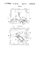
FIG. 3 is a longitudinal section as in FIG. 1 but with a selected rack in raised position,
FIG. 4 is a perspective view of a selected rack in raised position,
FIG. 5 is a longitudinal section through an embodiment of the invention having two annular turntables disposed one above the other, only the selected rack in raised position being partially enclosed within the wall of the vault,
FIG. 6 is a top plan view of the installation of FIG. 5, some parts being omitted for the sake of clarity,
FIG. 7 is a perspective view of a selected rack with safe-deposit boxes in another embodiment, having a partition and a withdrawal element,
FIG. 8 is a perspective view of the art of the withdrawal element of FIG. 7,
FIG. 9 is a longitudinal section of the withdrawal element of FIG. 7,
FIG. 10 is a top plan view, partially in section, of the withdrawal element and partition of FIG. 7,
FIG. 11 is a longitudinal section of a safe-deposit installation having two superposed pairs of annular turntables disposed one within the other,
FIG. 12 is a top plan view of the installation of FIG. 11, some parts being omitted for the sake of clarity,
FIG. 13 is a perspective view of the lifting arm having a telescoping cover plate,
FIG. 14 is a sectional view of an annular turntable driven by a sprocket wheel.
FIG. 15 is an elevation, partially in section, of a chain drive together with the packs and a roller train, and
FIG. 16 is a top plan view of the chain drive of FIG. 15.
The embodiment of the safe-deposit installation according to FIGS. 1-4 comprises an annular turntable 14 on which a number of racks 1, 2 are mounted singly and removably. A number of individually accessible safe-deposit boxes 4 are disposed one above the other in the rectangular, single- row racks 1, 2, accommodated in compartments 6 which are all situated on the same side of each rack 1, 2. A vertical rail 28 is affixed to each of the adjacent sides of these racks, which are detachably connected to turntable 14 by means of centering bolts 23, provided on the underside of each rack 1, 2 and snapping into matching recesses on turntable 14.
Turntable 14 and racks 1, 2 mounted thereon are enclosed within a vault 11 having at least one access aperture 12. A vertical hoist mechanism 7 passing through the center of turntable 14 comprises an upright 8 and, extending perpendicular thereto, a lifting arm 9 capable of traveling along upright 8. Arm 9 can be operated electro-mechanically, hydraulically, or pneumatically. In the case of the embodiment illustrated in FIG. 1, it is an electro-mechanical drive comprising an electric motor 32, a threaded spindle 33, and a part 34 screwed on spindle 33.
Turntable 14 rotates about its axis in a horizontal plane. It is supported on casters 22 which run on the floor of vault 11. A ring of ball bearings might be used instead of casters 22. At least three rollers 35 are provided for guiding turntable 14, as shown in FIG. 2. A drive mechanism comprises a sprocket wheel 36 meshing with the chain-like periphery 19 (cf. FIG. 14) of turntable 14. Another possibility would be to provide a fourth roller 35 having a friction surface to act as a drive roller.
As may be seen in FIGS. 1 and 3, upright 8 is secured to vault 11 and may be either fixed or rotary. Although illustrated here as being disposed within turntable 14, upright 8 might also be disposed outside the turntable. The sizes and arrangement of the safe-deposit box compartments in racks 1, 2 need not necessarily be as illustrated here but may be varied as desired. Furthermore, a number of hoist mechanisms may be provided within vault 11.
Through rotation of turntable 14, the selected rack 1a is brought into its starting position near the wall of vault 11 having the access aperture 12 and a shelf 40 (FIG. 1). Rack 1a is then seized by lifting arm 9 of hoist mechanism 7 in that centering cones or pins 9a and an angle iron 9b of arm 9 are slid under respective angle irons 25 and 26 of rack 1a. Pins 9a are thus positioned under holes 27 in angle irons 25 and snap into the latter when arm 9 is raised. Rack 1a, which is thus seized independently of the other racks 1, 2, is lifted straight up into the desired position in front of access aperture 12, being guided during this movement by means of rails 28 sliding in tracks 29 affixed to the wall of vault 11. Owing to the engagement of lifting arm 9 with the positioning device comprising angle irons 25, 26, and to the guidance provided by rails 28 and tracks 29, rack 1a is raised virtually free of shocks or vibration during its entire upward travel.
Disposed within vault 11 in front of aperture 12 is a vertically sliding armor-plate door 37. When door 37 is pushed upward, the dimensions of aperture 12 are automatically adapted to those of the particular safe-deposit box being presented. Thus door 37 ensures that aperture 12 is open only to the extent necessary for given access to the single safe-deposit box 4. The manner in which door 37 is operated is known per se.
In the wall of vault 11 having aperture 12 is a hatch 39 hung on hinges 38 and affording access to annular turntable 14, racks 1, 2, and hoist mechanism 7 for maintenance purposes.
FIGS. 5 and 6 show an embodiment of the safe-deposit installation having two superposed annular turntables 14 with racks 1. The two turntables 14 are accommodated in an underground room, with only part of hoist mechanism 7 projecting above ground and being enclosed by vault 11.
Arm 9 of hoist mechanism 7 is provided with an extension 31 (FIG. 6) which can be pulled out along arm 9 by means of a spindle (cf. FIG. 13). FIG. 6 shows guideways 41 on the top of each rack 1 into which extension 31 is inserted in order to raise the selected rack 1a. When rack 1a is returned to its starting position, the opening into the underground room is closed by extension 31, functioning as a cover plate.
A further embodiment of the safe-deposit installation is illustrated in FIGS. 7-10. Safe-deposit boxes 5 are held by racks 3 in compartments 6 opening out on a different side from those of racks 1 and 2. Accordingly, the interior of vault 11 is divided by a horizontal partition 18 situated at the level of access aperture 12. Partition 18 is secured to vault 11 and includes an opening 20 for hoist mechanism 7 and the selected rack 3a. A withdrawal element 21 is pivotingly mounted on partition 18. When element 21 is pivoted by an electric motor 43 over to the selected safe-deposit box 5a, the latter is seized by claws affixed to the arm 42 (FIG. 8) of element 21 and is pulled out of rack 3a laterally onto partition 18, independently of the other safe-deposit boxes 5. Arm 42 might seize safe-deposit box 5a electromagnetically instead of by means of claws.
The drawer 10 of safe-deposit box 5a is removed by the customer through access aperture 12 (FIG. 10). Rack 3a with the other safe-deposit boxes 5 is then returned by hoist mechanism 7 to its starting position or to another position remote from partition 18.
Finally, FIGS. 11 and 12 illustrate still another embodiment of the safe-deposit installation comprising two superposed pairs of turn-tables 14, 15 disposed one within the other for space-saving purposes. As may be seen in FIG. 11, two motors are provided, one for driving the outer turntables and the other for the inner turntables. Upper turntable 15 includes an opening through which selected rack 1 is conveyed when raised from lower turntable 14, as also shown in FIG. 11.
FIGS. 13 and 14 are to be taken in conjunction with FIGS. 6 and 2, respectively, as mentioned earlier.
FIGS. 15 and 16 show a chain drive which may be used instead of the annular turntables. A chain 16 runs along a circular or oval path 17 (FIG. 16). Affixed to chain 16 are racks 1, 2, 3 having differently arranged compartments for the safe-deposit boxes. The racks run over a conveyor 30, preferably a roller train.
The safe-deposit installation described above may be situated in a public building or outside. In front of the installation is an anteroom where the customer is protected while using the facility. It cannot be entered unless the customer first identifies himself, e.g., by keying in a code number with a code card or in some other manner. Not until the customer has thus identified himself satisfactorily, and the anteroom is free, can the door of that room be opened to admit him. Inside the anteroom, the customer again identifies himself to the safe-deposit installation by keying in a code number. If the number is correct and the anteroom door is locked, the desired safe-deposit box from the selected rack will be moved into the position behind the armor-plate door at the access aperture. The armor-plate door then slides open, and the safe-deposit box becomes accessible to the customer, so that he can open it with his key and lock it again when he is finished with it. The armor-plate door closes automatically, and the customer leaves the anteroom.
This safe-deposit installation offers security advantages inasmuch as the selected rack is raised up away from the remaining racks, so that there is no possibility of access from a safe-deposit box in one rack to that of another rack. Even if an authorized-access box is opened and then broken through at the side, there is nothing but empty space next to it. Since no two-dimensional movement takes place in the safe-deposit installation, but only horizontal movements of the conveying means and vertical movements of the hoist mechanism, successively and separately, this means added security. The individual racks can be exchanged, or the sizes changed, after opening of the maintenance hatch of the vault. The conveying means can likewise be adapted to the respective vault size or to the rooms. The safe-deposit installation also makes it possible to provide several access apertures at various floor levels with access to the individual racks. Finally, provision may be made for purely manual mechanical operation, e.g., in case the electricity goes off, but only in the presence of a supervisory person.

Claims (10)

What is claimed is:
1. A safe-deposit installation of the type having a plurality of rectangular racks, a plurality of individually accessible safe-deposit boxes disposed one above said other in each of said racks and including compartments for receiving said safe-deposit boxes, said compartments all opening out on one side of each of said racks, and a vault surrounding said racks at least partially and including at least one access aperture, wherein the improvement comprises:
at least one vertical hoist mechanism situated within said vault and including means for seizing and raising a selected one of said racks to the level of said access aperture independently of the other said racks,
conveyor means separate from said hoist mechanism and movable in a horizontal plane for presenting said selected one of said racks to said hoist mechanism,
means for affixing said racks individually and detachably to said conveyor means,
each of said racks containing only a single row of said safe-deposit boxes, wherein said compartments are of various sizes, and said conveying means takes the form of at least one annular turntable, further comprising rolling means disposed beneath said turntable, said means for affixing said racks to said conveyor means taking the form of centering pins, each of said racks comprising positioning means, and said hoist mechanism comprising an upright and a lifting arm perpendicular to and movable along said upright and including further centering pins intended to engage said positioning means.
2. The safe-deposit installation of claim 1, wherein said rolling means take the form of casters.
3. The safe-deposit installation of claim 1, wherein said rolling means take the form of a ring of ball bearings.
4. The safe-deposit installation of claim 1, wherein said positioning means comprise two angle irons secured to each of said racks, one of said angle irons including holes for receiving said further centering pins.
5. The safe-deposit installation of claim 1 comprising a plurality of superposed said annular turntables.
6. The safe-deposit installation of claim 1, comprising a plurality of pairs of said annular turntables disposed one within the other.
7. The safe-deposit installation of claim 1, further comprising a cover plate telescopingly mounted on said lifting arm.
8. The safe-deposit installation of claim 1, wherein said hoist mechanism is situated outside said conveying means.
9. A safe-deposit installation of the type having a plurality of rectangular racks, a plurality of individually accessible safe-deposit boxes disposed one above said other in each of said racks and including compartments for receiving said safe-deposit boxes, said compartments all opening out on one side of each of said racks, and a vault surrounding said racks at least partially and including at least one access aperture, wherein the improvement comprises:
at least one vertical hoist mechanism situated within said vault and including means for seizing and raising a selected one of said racks to the level of said access aperture independently of the other said racks,
conveyor means separate from said hoist mechanism and movable in a horizontal plane for presenting said selected one of said racks to said hoist mechanism,
means for affixing said racks individually and detachably to said conveyor means,
each of said racks containing only a single row of said safe-deposit boxes, further comprising a horizontal partition secured to said vault and dividing the interior of said vault at the level of said access aperture, said partition including an opening for the passage of said hoist mechanism and said selected one of said racks, a withdrawal element pivoted on said partition for withdrawing a selected one of said safe-deposit boxes from said selected one of said racks onto said partition, and means for returning said selected one of said racks to a position remote from said access aperture.
10. A safe-deposit installation of the type having a plurality of rectangular racks, a plurality of individually accessible safe-deposit boxes disposed one above said other in each of said racks and including compartments for receiving said safe-deposit boxes, said compartments all opening out on one side of each of said racks, and a vault surrounding said racks at least partially and including at least one access aperture, wherein the improvement comprises:
at least one vertical hoist mechanism situated within said vault and including means for seizing and raising a selected one of said racks to the level of said access aperture independently of the other said racks,
conveyor means separate from said hoist mechanism and movable in a horizontal plane for presenting said selected one of said racks to said hoist mechanism,
means for affixing said racks individually and detachably to said conveyor means,
each of said racks containing only a single row of said safe-deposit boxes, further comprising two vertical rails respectively affixed to opposing sides of each of said racks, and two vertical tracks affixed to said vault, matching said rails, and co-operating therewith for guiding said selected one of said racks.
US06/936,458 1985-12-05 1986-12-01 Safe-deposit installation Expired - Fee Related US4724774A (en)

Applications Claiming Priority (1)

Application Number Priority Date Filing Date Title
CH518685 1985-12-05

Publications (1)

Publication Number Publication Date
US4724774A true US4724774A (en) 1988-02-16

Family

ID=4289365

Family Applications (1)

Application Number Title Priority Date Filing Date
US06/936,458 Expired - Fee Related US4724774A (en) 1985-12-05 1986-12-01 Safe-deposit installation

Country Status (7)

Country Link
US (1) US4724774A (en)
EP (1) EP0225289B1 (en)
JP (1) JPS62146382A (en)
AT (1) ATE48877T1 (en)
CA (1) CA1298520C (en)
DE (1) DE3667686D1 (en)
ES (1) ES2012357B3 (en)

Cited By (9)

* Cited by examiner, † Cited by third party
Publication number Priority date Publication date Assignee Title
DE9115604U1 (en) * 1991-12-17 1992-02-27 Petratschek, Ingo Norbert, 8500 Nuernberg, De
US5257582A (en) * 1992-12-11 1993-11-02 Santa Barbara Bank & Trust Vault capacity expansion system
US5722332A (en) * 1995-12-28 1998-03-03 M.I.B. Elettronica S.R.L. Apparatus and process for conducting deposit and drawing operations of banknotes and valuables
GB2360327A (en) * 2000-03-14 2001-09-19 Spinnaker Int Ltd Security system having a plurality of restricted access compartments
US6536859B1 (en) * 1999-08-03 2003-03-25 Carl Zeiss Jena Gmbh Climatic cabinet
US6609773B1 (en) * 1998-10-14 2003-08-26 William D. Steadman Storage apparatus
US20060290248A1 (en) * 2005-06-27 2006-12-28 Joe Chandler Table with electric hidden storage
US20110079170A1 (en) * 2009-10-01 2011-04-07 Abdullah Ali Al-Mutairi Security system for storing firearms
DE102021001954A1 (en) 2021-04-14 2022-11-03 Amjad Al Barazi Mobile locker system with fingerprint technology

Families Citing this family (8)

* Cited by examiner, † Cited by third party
Publication number Priority date Publication date Assignee Title
EP0310557A1 (en) * 1987-09-29 1989-04-05 Vidmar AG Safety arrangement for storing valuables
NL8702444A (en) * 1987-10-13 1989-05-01 Windson Holding Bv SAFE.
DE69014319T2 (en) * 1989-01-19 1995-05-18 Mib Elettronica Device for protecting and processing banknotes and valuables.
IT1253100B (en) * 1991-12-24 1995-07-10 Cespro Srl SAFETY BOX FOR THE DEPOSIT AND, RESPECTIVELY, THE WITHDRAWAL OF THE VALUES
NL1013860C2 (en) * 1999-12-15 2001-06-25 Ergotrans B V Valuable objects delivering method e.g. for foreign currency, medicines, involves identifying client, based on which valuable objects are delivered under control of user interface program
CN1533971B (en) * 2003-03-31 2010-09-29 株式会社久保田 Device for stacking seedling growing box
CN108523475B (en) * 2018-04-11 2019-11-05 重庆圆佳快递有限公司 A kind of express delivery locker
CN109292338B (en) * 2018-10-25 2020-09-18 西安银马实业发展有限公司 Automatic storing, taking and transferring system for industrial production process

Citations (4)

* Cited by examiner, † Cited by third party
Publication number Priority date Publication date Assignee Title
US1062056A (en) * 1912-02-17 1913-05-20 David K Thomas Safe and vault.
US3587485A (en) * 1969-12-24 1971-06-28 Frank J Shea Security vault
US4108518A (en) * 1977-03-31 1978-08-22 Angst Edy P Banquet food serving apparatus
EP0140839A2 (en) * 1983-10-31 1985-05-08 Pierre E. Locher Safe arrangement and method of operating it

Family Cites Families (12)

* Cited by examiner, † Cited by third party
Publication number Priority date Publication date Assignee Title
SE382796C (en) * 1973-08-22 1977-10-27 Robur Konsult Ab DEVICE FOR AUTOMATED HANDLING OF BANK CASSETTE
IL64015A (en) * 1980-10-24 1984-10-31 Pretini Gisberto Automated bank counter
JPS58222281A (en) * 1982-06-17 1983-12-23 株式会社ダイフク Storing installation
JPS5948581A (en) * 1982-09-10 1984-03-19 株式会社ダイフク Accommodation installation
DE3240955A1 (en) * 1982-11-05 1984-05-10 Fa. Schlüter Banktechnik, 5340 Bad Honnef Safe-deposit box installation
JPS59149206A (en) * 1983-02-17 1984-08-27 Daifuku Co Ltd Storage facility with access device
JPS59158705A (en) * 1983-02-24 1984-09-08 Daifuku Co Ltd Push-pull transfer loader
JPS59163202A (en) * 1983-03-05 1984-09-14 Nippon Filing Co Ltd Keeping equipment of secret article
JPS59170383A (en) * 1983-03-16 1984-09-26 株式会社 伊藤喜工作所 Automatic safe-deposit box system
JPS6052403A (en) * 1983-08-08 1985-03-25 Nippon Filing Co Ltd Secret deposit storing installation
JPS6098082A (en) * 1983-10-31 1985-06-01 株式会社イトーキクレビオ Lental strong box
FR2557189B1 (en) * 1983-12-27 1986-05-09 Securite Services Cie Europ STRONG ROOM INSTALLATION FOR BANKS

Patent Citations (4)

* Cited by examiner, † Cited by third party
Publication number Priority date Publication date Assignee Title
US1062056A (en) * 1912-02-17 1913-05-20 David K Thomas Safe and vault.
US3587485A (en) * 1969-12-24 1971-06-28 Frank J Shea Security vault
US4108518A (en) * 1977-03-31 1978-08-22 Angst Edy P Banquet food serving apparatus
EP0140839A2 (en) * 1983-10-31 1985-05-08 Pierre E. Locher Safe arrangement and method of operating it

Cited By (11)

* Cited by examiner, † Cited by third party
Publication number Priority date Publication date Assignee Title
DE9115604U1 (en) * 1991-12-17 1992-02-27 Petratschek, Ingo Norbert, 8500 Nuernberg, De
US5257582A (en) * 1992-12-11 1993-11-02 Santa Barbara Bank & Trust Vault capacity expansion system
US5722332A (en) * 1995-12-28 1998-03-03 M.I.B. Elettronica S.R.L. Apparatus and process for conducting deposit and drawing operations of banknotes and valuables
US6609773B1 (en) * 1998-10-14 2003-08-26 William D. Steadman Storage apparatus
US6536859B1 (en) * 1999-08-03 2003-03-25 Carl Zeiss Jena Gmbh Climatic cabinet
GB2360327A (en) * 2000-03-14 2001-09-19 Spinnaker Int Ltd Security system having a plurality of restricted access compartments
GB2360327B (en) * 2000-03-14 2002-01-30 Spinnaker Int Ltd Security system
US20060290248A1 (en) * 2005-06-27 2006-12-28 Joe Chandler Table with electric hidden storage
US20110079170A1 (en) * 2009-10-01 2011-04-07 Abdullah Ali Al-Mutairi Security system for storing firearms
DE102021001954A1 (en) 2021-04-14 2022-11-03 Amjad Al Barazi Mobile locker system with fingerprint technology
DE102021001954B4 (en) 2021-04-14 2023-01-19 Amjad Al Barazi Mobile locker system with fingerprint technology

Also Published As

Publication number Publication date
ATE48877T1 (en) 1990-01-15
EP0225289A1 (en) 1987-06-10
EP0225289B1 (en) 1989-12-20
JPS62146382A (en) 1987-06-30
ES2012357B3 (en) 1990-03-16
CA1298520C (en) 1992-04-07
DE3667686D1 (en) 1990-01-25

Similar Documents

Publication Publication Date Title
US4724774A (en) Safe-deposit installation
CA1057582A (en) Protection plant in a room against penetration thereinto of ill-intentioned persons
US4975012A (en) Mechanized storage facility
DE2934516C2 (en)
US3964577A (en) Automated handling system for bank deposit boxes
US9260245B2 (en) System and method for automatic storage and withdrawal of products with security restrictions
US5970888A (en) Bank teller station
CN201963114U (en) Full-automatic safe deposit box
JPH01187283A (en) Safe-deposit box device
US3770105A (en) Product displaying, selective, dispensing apparatus
US4061379A (en) Locker system
US1593665A (en) Storage building
US3602379A (en) Materials handling device
US3298765A (en) Cash drawers and method for operating same
US3149708A (en) Round th' clock cleaners
JPS608054Y2 (en) safe deposit box
JPH0622825A (en) Automatic management locker device for baggage or the like
US5857418A (en) Device for storing valuable objects
US20210043024A1 (en) Assembly for product support and deployment for a vending machine
EP0230643A2 (en) Safe
EP0492471A1 (en) Mechanised system for the storage and transfer of safety-deposit boxes, for example for banks
WO2007071988A1 (en) Storage systems
CN211894667U (en) Intelligent full-automatic tail box warehouse
JPH022864Y2 (en)
CN111028435A (en) Automatic deposit cabinet of access

Legal Events

Date Code Title Description
AS Assignment

Owner name: VIDMAR AG, NEUENGASSE 25, 3011 BERN/SWITZERLAND

Free format text: ASSIGNMENT OF ASSIGNORS INTEREST.;ASSIGNORS:WIEDEMAR, HANS;WIEDEMAR, DANIEL;REEL/FRAME:004638/0311

Effective date: 19861117

Owner name: VIDMAR AG,SWITZERLAND

Free format text: ASSIGNMENT OF ASSIGNORS INTEREST;ASSIGNORS:WIEDEMAR, HANS;WIEDEMAR, DANIEL;REEL/FRAME:004638/0311

Effective date: 19861117

REMI Maintenance fee reminder mailed
LAPS Lapse for failure to pay maintenance fees
FP Lapsed due to failure to pay maintenance fee

Effective date: 19920216

STCH Information on status: patent discontinuation

Free format text: PATENT EXPIRED DUE TO NONPAYMENT OF MAINTENANCE FEES UNDER 37 CFR 1.362