US4706360A - Thread gage - Google Patents
Thread gage Download PDFInfo
- Publication number
- US4706360A US4706360A US06/862,859 US86285986A US4706360A US 4706360 A US4706360 A US 4706360A US 86285986 A US86285986 A US 86285986A US 4706360 A US4706360 A US 4706360A
- Authority
- US
- United States
- Prior art keywords
- thread
- stylus
- turret
- workpiece
- gage
- Prior art date
- Legal status (The legal status is an assumption and is not a legal conclusion. Google has not performed a legal analysis and makes no representation as to the accuracy of the status listed.)
- Expired - Fee Related
Links
Images


Classifications
-
- G—PHYSICS
- G01—MEASURING; TESTING
- G01B—MEASURING LENGTH, THICKNESS OR SIMILAR LINEAR DIMENSIONS; MEASURING ANGLES; MEASURING AREAS; MEASURING IRREGULARITIES OF SURFACES OR CONTOURS
- G01B7/00—Measuring arrangements characterised by the use of electric or magnetic techniques
- G01B7/14—Measuring arrangements characterised by the use of electric or magnetic techniques for measuring distance or clearance between spaced objects or spaced apertures
- G01B7/148—Measuring on screw threads
-
- G—PHYSICS
- G01—MEASURING; TESTING
- G01B—MEASURING LENGTH, THICKNESS OR SIMILAR LINEAR DIMENSIONS; MEASURING ANGLES; MEASURING AREAS; MEASURING IRREGULARITIES OF SURFACES OR CONTOURS
- G01B21/00—Measuring arrangements or details thereof, where the measuring technique is not covered by the other groups of this subclass, unspecified or not relevant
- G01B21/20—Measuring arrangements or details thereof, where the measuring technique is not covered by the other groups of this subclass, unspecified or not relevant for measuring contours or curvatures, e.g. determining profile
-
- G—PHYSICS
- G01—MEASURING; TESTING
- G01B—MEASURING LENGTH, THICKNESS OR SIMILAR LINEAR DIMENSIONS; MEASURING ANGLES; MEASURING AREAS; MEASURING IRREGULARITIES OF SURFACES OR CONTOURS
- G01B7/00—Measuring arrangements characterised by the use of electric or magnetic techniques
- G01B7/28—Measuring arrangements characterised by the use of electric or magnetic techniques for measuring contours or curvatures
- G01B7/284—Measuring arrangements characterised by the use of electric or magnetic techniques for measuring contours or curvatures of screw-threads
-
- G—PHYSICS
- G05—CONTROLLING; REGULATING
- G05B—CONTROL OR REGULATING SYSTEMS IN GENERAL; FUNCTIONAL ELEMENTS OF SUCH SYSTEMS; MONITORING OR TESTING ARRANGEMENTS FOR SUCH SYSTEMS OR ELEMENTS
- G05B19/00—Program-control systems
- G05B19/02—Program-control systems electric
- G05B19/18—Numerical control [NC], i.e. automatically operating machines, in particular machine tools, e.g. in a manufacturing environment, so as to execute positioning, movement or co-ordinated operations by means of program data in numerical form
- G05B19/401—Numerical control [NC], i.e. automatically operating machines, in particular machine tools, e.g. in a manufacturing environment, so as to execute positioning, movement or co-ordinated operations by means of program data in numerical form characterised by control arrangements for measuring, e.g. calibration and initialisation, measuring workpiece for machining purposes
-
- G—PHYSICS
- G05—CONTROLLING; REGULATING
- G05B—CONTROL OR REGULATING SYSTEMS IN GENERAL; FUNCTIONAL ELEMENTS OF SUCH SYSTEMS; MONITORING OR TESTING ARRANGEMENTS FOR SUCH SYSTEMS OR ELEMENTS
- G05B2219/00—Program-control systems
- G05B2219/30—Nc systems
- G05B2219/37—Measurements
- G05B2219/37043—Touch probe, store position of touch point on surface
-
- G—PHYSICS
- G05—CONTROLLING; REGULATING
- G05B—CONTROL OR REGULATING SYSTEMS IN GENERAL; FUNCTIONAL ELEMENTS OF SUCH SYSTEMS; MONITORING OR TESTING ARRANGEMENTS FOR SUCH SYSTEMS OR ELEMENTS
- G05B2219/00—Program-control systems
- G05B2219/30—Nc systems
- G05B2219/37—Measurements
- G05B2219/37207—Verify, probe, workpiece
-
- G—PHYSICS
- G05—CONTROLLING; REGULATING
- G05B—CONTROL OR REGULATING SYSTEMS IN GENERAL; FUNCTIONAL ELEMENTS OF SUCH SYSTEMS; MONITORING OR TESTING ARRANGEMENTS FOR SUCH SYSTEMS OR ELEMENTS
- G05B2219/00—Program-control systems
- G05B2219/30—Nc systems
- G05B2219/37—Measurements
- G05B2219/37606—Thread form, parameters
-
- G—PHYSICS
- G05—CONTROLLING; REGULATING
- G05B—CONTROL OR REGULATING SYSTEMS IN GENERAL; FUNCTIONAL ELEMENTS OF SUCH SYSTEMS; MONITORING OR TESTING ARRANGEMENTS FOR SUCH SYSTEMS OR ELEMENTS
- G05B2219/00—Program-control systems
- G05B2219/30—Nc systems
- G05B2219/45—Nc applications
- G05B2219/45214—Gear cutting
-
- Y—GENERAL TAGGING OF NEW TECHNOLOGICAL DEVELOPMENTS; GENERAL TAGGING OF CROSS-SECTIONAL TECHNOLOGIES SPANNING OVER SEVERAL SECTIONS OF THE IPC; TECHNICAL SUBJECTS COVERED BY FORMER USPC CROSS-REFERENCE ART COLLECTIONS [XRACs] AND DIGESTS
- Y10—TECHNICAL SUBJECTS COVERED BY FORMER USPC
- Y10T—TECHNICAL SUBJECTS COVERED BY FORMER US CLASSIFICATION
- Y10T29/00—Metal working
- Y10T29/49—Method of mechanical manufacture
- Y10T29/49764—Method of mechanical manufacture with testing or indicating
- Y10T29/49771—Quantitative measuring or gauging
-
- Y—GENERAL TAGGING OF NEW TECHNOLOGICAL DEVELOPMENTS; GENERAL TAGGING OF CROSS-SECTIONAL TECHNOLOGIES SPANNING OVER SEVERAL SECTIONS OF THE IPC; TECHNICAL SUBJECTS COVERED BY FORMER USPC CROSS-REFERENCE ART COLLECTIONS [XRACs] AND DIGESTS
- Y10—TECHNICAL SUBJECTS COVERED BY FORMER USPC
- Y10T—TECHNICAL SUBJECTS COVERED BY FORMER US CLASSIFICATION
- Y10T409/00—Gear cutting, milling, or planing
- Y10T409/30—Milling
- Y10T409/303752—Process
-
- Y—GENERAL TAGGING OF NEW TECHNOLOGICAL DEVELOPMENTS; GENERAL TAGGING OF CROSS-SECTIONAL TECHNOLOGIES SPANNING OVER SEVERAL SECTIONS OF THE IPC; TECHNICAL SUBJECTS COVERED BY FORMER USPC CROSS-REFERENCE ART COLLECTIONS [XRACs] AND DIGESTS
- Y10—TECHNICAL SUBJECTS COVERED BY FORMER USPC
- Y10T—TECHNICAL SUBJECTS COVERED BY FORMER US CLASSIFICATION
- Y10T409/00—Gear cutting, milling, or planing
- Y10T409/30—Milling
- Y10T409/308624—Milling with limit means to aid in positioning of cutter bit or work [e.g., gauge, stop, etc.]
-
- Y—GENERAL TAGGING OF NEW TECHNOLOGICAL DEVELOPMENTS; GENERAL TAGGING OF CROSS-SECTIONAL TECHNOLOGIES SPANNING OVER SEVERAL SECTIONS OF THE IPC; TECHNICAL SUBJECTS COVERED BY FORMER USPC CROSS-REFERENCE ART COLLECTIONS [XRACs] AND DIGESTS
- Y10—TECHNICAL SUBJECTS COVERED BY FORMER USPC
- Y10T—TECHNICAL SUBJECTS COVERED BY FORMER US CLASSIFICATION
- Y10T82/00—Turning
- Y10T82/25—Lathe
- Y10T82/2585—Tool rest
- Y10T82/2587—Turret type holder [e.g., multiple tools, etc.]
Definitions
- the present invention relates to thread gages. More particularly, the present invention relates to gaging apparatus and a method of gaging threads wherein a stylus is caused to follow along the profile of a thread surface and is connected to a transducer which translates the movement of the stylus into a set of electrical signals which may then be compared to a digital model of a standard thread for comparison thereto.
- Thread forms consist of a large number of parameters which are interrelated. These thread form parameters include pitch diameter, pitch cylinder, pitch, major diameter, minor diameter, included angle, helix angle, and lead angle. The interrelationship between these various thread parameters is such that a variation in one of them will cause variations in others of them. For example, a variation in the included angle may cause a variation of the pitch diameter and the minor diameter.
- Bench-type gage structures such as disclosed in U.S. Pat. No. 3,319,341 to Graham do not provide the rapid measurement of threads and do not provide for rapid correction thereof as is desired for modern production machinery.
- such gage structures of the bench-type do not lend themselves readily to measuring the thread of every workpiece as soon as it is produced since this would require the time consuming process of setting up the threaded workpiece for measurement each time a thread thereof is to be measured.
- there may be a tendency in using such bench-type gage structures to use them only as audit type quality control gages, i.e., to only measure the threads of a random number of workpieces and thus not achieve the preciseness of thread form for every machined part as may be desired.
- Graham proposes complicated improvements involving shock absorbing and damping means and relocating of the vibrator on the carriage. Not only are such complicated vibration and shock absorbing means undoubtedly unreliable but the use of such equipment should have the effect of slowing the equipment down so that it takes longer to gage a thread portion than it would otherwise take.
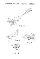
- FIG. 1 is a schematic view of a thread gage embodying the present invention
- FIG. 2 is a view similar to that of FIG. 1 of an alternative embodiment of a thread gage of the present invention
- FIG. 3 is a plan view of the alternative embodiment of the thread gage of FIG. 2;
- FIG. 4 is a diagrammatic view illustrating the linkage geometry for the thread gage of FIG. 3;
- FIG. 5 is a view similar to that of FIG. 4 illustrating the geometry for plotting the pivot point constraint region for the thread gage of FIG. 3;
- FIG. 6 is a view similar to that of FIG. 4 illustrating a free body diagram of the linkage system for the thread gage of FIG. 3;
- FIG. 7 is a schematic partial view of another embodiment of a thread gage of the present invention.
- FIG. 8 is a perspective partial view of the rotary variable displacement transducer of FIG. 7.
- FIG. 1 there is shown at 10 a workpiece portion held in a workpiece holder 12 of a production threading machine. Illustrated at 14 is a thread which has been cut in the workpiece 10 by the production threading machine. Although internal threads are illustrated in the drawings, it is understood that a thread gage embodying the present invention may also be used to measure external threads. As the term is used in this specification and claims, the term “thread” is meant to refer to a contoured portion of a workpiece including, but not limited to grooves, undulations, threads, inclined planes, and the like.
- the production threading machine includes a turret illustrated at 16 which is a revolvable holder of two or more tools or the like for performing in sequence two or more operations on a workpiece 10.
- a turret illustrated at 16 which is a revolvable holder of two or more tools or the like for performing in sequence two or more operations on a workpiece 10.
- one such tool may be a drill for forming the hole in which thread 14 is cut and another such tool may be a threaded tool for cutting the thread 14.
- the turret 16 is movable in the directions illustrated at 18 which are axially of the workpiece holder 12 and of the thread 14 cut in the workpiece 10.
- a reliable yet structurally non-complex thread gage which has a minimum of moving parts is generally illustrated at 19.
- the thread gage includes a stylus means or follower 20 which has a tip 21 which is caused to move or follow over the surface of the thread 14 and thus map the thread contour as the stylus is moved in a direction 18 axially of the thread 14, preferably in the axial direction illustrated at 22 to thus pull the stylus over the thread surface, with the workpiece 10 held in a non-rotating stationary position.
- the stylus 20 may be held stationary while the workpiece 10 is moved in an axial direction 18.
- Thread gage 19 is preferably set up to climb the less steep thread faces and biased to move down the steeper thread faces.
- the thread contour will effect movement of the stylus tip 21 in directions illustrated at 24 radially of the thread 14, the stylus 20 being biased radially by suitable biasing means as will be described hereinafter to engage the thread surface.
- radial and axial directions are meant to refer to directions perpendicular to and parallel to respectively the axis of rotation of a workpiece holder and the thread of a threaded member held therein to be measured by a thread gage of the present invention. It is understood that movement may be in both axial and radial directions at the same time.
- the stylus 20 is mounted directly to the shaft or in-line probe 26 of a linear variable displacement transformer (hereinafter called "LVDT") 28 or other suitable transducer means which provides good linearity, repeatability, and sensitivity.
- the LVDT 28 which may have spring means (not shown) internally thereof to provide the aforesaid biasing of the stylus for radial movement, is mounted on a support means 30 for supporting the LVDT 28 and stylus 20 in position for following the thread contour.
- the diameter of the stylus tip 21 is preferably small enough, such as 0.0015 inch, to engage the root of the thread to be measured.
- the LVDT 28 an instrument commonly known to those of ordinary skill in the art to which this invention pertains, is provided to translate the linear displacement of the stylus tip 21 in radial directions 24 into a set of electrical signals which correspond to the position of the stylus tip 21 in the axial directions 18 and to amplify these signals in the signal amplifier illustrated at 32 so that these signals may be used to provide a digital model of the thread 14 as will be described hereinafter.
- An LVDT is an electromechanical device that produces an output proportional to the displacement of a separate movable core, i.e., probe 26. It includes a primary coil (not shown) and two secondary coils (not shown) spaced symmetrically.
- a free-moving rod magnetic core (not shown) inside the coil assembly provides a path for the magnetic flux linking the coils.
- the primary coil When the primary coil is energized by an external alternating current source, voltages are induced in the two secondary coils. The coils are connected in opposing series so the two voltages are of opposite polarity. The net output of the transducer is the difference between these induced voltages. The output is zero when the core or probe 26 is at a center or null position. As the core or probe 26 is displaced from the null position, the induced voltage increases in one coil and decreases in the opposite coil.
- the stylus tip displacement is mechanically amplified at the transducer core depending on the relative arm-to-pivot-length ratios. Thus, stylus motions caused by the thread form produce transducer outputs to result in high sensitivity and accuracy.
- means such as connecting member 34 for connecting the LVDT and stylus support 30 to the production threading machine turret 16 whereby, after a thread is cut, the turret 16 may be revolved into position for quickly and efficiently positioning the stylus 20 for gaging or measuring the thread 14.
- the production threading machine's tool slides may be used as the traversing mechanism for movement of the stylus in the directions 18 axially of the thread.
- the output of the LVDT 28 is connected to the computer control system illustrated at 35 of the production threading maching which computer control 35 is programmed to provide information relative to the position of the stylus tip 21 in the axial directions 18 based on the position of the machine turret 16. Such information, i.e., position of the turret, would typically be programmed in the computer control 35 for various other machine operations.
- Computer control 35 is also preferably programmed with a digital model of a standard thread against which it is desired to compare thread 14. In the comparator portion illustrated at 36 of the computer control 35, the signal from the LVDT 28 is digitized and compared to the digital model of the standard thread.
- the output of the comparator 36 may be provided to a digital printout illustrated at 38 and/or a chart recorder illustrated at 40.
- the chart recorder 40 may provide an analog output displayed on a strip chart.
- the printout 38 may be a tabular printer capable of printing the numeric values for the various thread form parameters.
- the comparator 36 may also be programmed to compare the difference between the actual readings provided by the LVDT 28 and the mathematical model of a standard thread to a set of predetermined limits and to provide the output to machine control 35 which may then make the accept/reject decision based upon whether or not the difference is within or outside of the predetermined limits.
- the computer control 35 may also be programmed to generate machine updates to the tool offset register based upon such comparisons to thus allow the production threading machine to automatically increase the tool offset within specified limits so that later produced workpieces will have thread parameters closer to those of the standard thread. Comparisons of thread profiles may be used to perform tool wear time studies, to look for gradual or rapid break-down of a tool, or to determine that a tool is chipped.
- the thread gage may be used by rotating the turret to a predetermined position for positioning the stylus 20 so that its tip 21 contacts the thread surface.
- the axial position of the stylus tip 21, being related to the axial position of the turret 16, is recorded in the machine computer control 35.
- the turret 16 is caused to move in an axial direction 18 to thus cause the stylus tip to move in an axial direction, preferably the direction illustrated at 22.
- the LVDT 28 translates the radial positions of the stylus tip 21 corresponding to axial positions thereof into electrical signals which are then transmitted to the signal amplifier 32 where the signals are amplified and then transmitted to the machine computer control 35 where a digital model of the thread 14 is produced from the signals indicating the axial positions of the turret 16 and the LVDT signals indicating the radial position of the stylus tip 21 at each axial position of the turret 16.
- This digital model is compared in the comparator 36 with a digital model of a standard thread which has been predetermined and programmed therein. The difference between the actual readings provided by the LVDT 28 and the mathematical model of a standard thread is compared to a set of predetermined limits.
- the machine computer control 35 may be programmed to automatically accept or reject the workpiece 10 based upon whether or not the difference is inside or outside of the predetermined limits and perhaps also to generate a machine update to the tool offset register if the difference is outside the predetermined limits.
- a thread gage embodying the present invention is provided to allow the contour of each thread to be automatically and quickly and accurately checked against a standard thread contour while still set up in the thread cutting machine after the thread is cut so that it may be automatically rejected if the measurements are outside the range of acceptability.
- FIG. 2 illustrates an alternative embodiment of the present invention wherein 50 represents a workpiece portion, 52 represents a workpiece holder, 54 represents a thread cut in the workpiece, 56 illustrates a production threading machine turret, 58 illustrates generally a thread gage in accordance with the alternative embodiment, 60 illustrates a stylus for following the thread contour, 61 illustrates the stylus tip, and 62 illustrates the shaft or probe for LVDT 64 all of which elements correspond to similarly named elements in FIG. 1.
- LVDT 64 is fixed to a foundation 66 and its shaft or probe 62 is pivotally connected to stylus 60 by linkage means including links 68 and 70.
- Link 70 is connected between link 68 and probe 62 by pin joints 72 and 74 respectively.
- Link 68 is pivotally connected to turret 56 of the production threading machine at member 76 to rotatably move about pviot point member 78, which member 76 is fixed to turret 56 and pivot point member or shaft 78 is connected to member 76, so that movement of the turret 56 in a direction illustrated at 80 axially of the thread (preferably the direction illustrated at 81) will effect movement of the stylus tip 61 axially of the thread, and the links 68 and 70 will transmit the stylus tip position to the probe 62 of LVDT 64.
- Turret 56 and foundation 66 are either connected or otherwise adapted for movement at the same rate of speed.
- the signals generated by LVDT 64 are then amplified and transmitted to the machine computer control for use similarly as described for the embodiment of FIG. 1.
- FIG. 3 is a plan view of a thread gage 100 similar to the thread gage 58 schematically illustrated in FIG. 2.
- At 102 is a member provided for mounting of the gage 100 by connecting means illustrated at 101 to a production threading machine turret 103 for movement in directions illustrated at 104 axially of a thread 160 to be measured by gage 100 so that movement of the thread gage 100 is in a direction parallel to the rotational axis of a thread 160 to be measured.
- LVDT 106 Connected to mounting member 102 by suitable connecting means illustrated at 125 is LVDT 106 for movement therewith.
- LVDT 106 which is similar to LVDTs 28 and 64 in FIGS.
- a stylus holder 114 is connected at one end portion to one end portion 115 of the pivot arm 112 by suitable connecting means illustrated at 116.
- the stylus holder 114 and pivot arm 112 in combination correspond to and function similarly to link 68 in FIG. 2.
- Extending perpendicularly from the other end portion of the stylus holder 114 and connected thereto by suitable connecting means illustrated at 118 is stylus 120 which tapers to a tip 122, similar to stylus and tip 60 and 61 respectively of FIG. 2, for engaging a thread face 158 wherein movements of the stylus tip 122 in directions, illustrated at 134, radially of the thread 160 are changed to rotary movements, illustrated at 123, about the pivot point member 110.
- LVDT probe 108 is threadedly or otherwise suitably attached to linkage member 126, such as by internal threaded connection illustrated at 127.
- Link 128 is pivotally connected to linkage member 126 at pivot shaft 130 at one end portion and to the end portion 117 of pivot arm 112 at pivot shaft 132 at the other end portion thereof, and sized and positioned, in accordance with engineering principles of common knowledge to those of ordinary skill in the art to which this invention pertains, to provide suitable resolution of the rotary movements 123 of the pivot arm 112 to linear movements in axial directions 104 for input to the LVDT 106 via probe 108 and without binding of the LVDT 106.
- Suitable ball bearings 133 are provided to facilitate the pivotal movements at the pivot shafts 110, 130, and 132, and the pivot shafts are retained in position by suitable retainer rings 135.
- Such linkage between the pivot arm 112 and LVDT 106 may be constructed using principles of common knowledge to those of ordinary skill in the art to which this invention pertains.
- the pivot arm 112 includes a first portion 136 (which terminates at edn portion 117) which extends in direction 134 generally radially of the thread between the pivot shafts 110 and 132 and further includes a second portion 138 (which terminates at end portion 115).
- the second portion 138 together with the stylus holder 114 extend generally between the pivot shaft 110 and stylus 120 at an angle relative to the radial and axial directions 134 and 104 respectively which will be described hereinafter.
- Link 128 as well as linkage member 126 and LVDT probe 108 extend generally in the axial direction 104, but a gage may be built in accordance with the present invention, in accordance with principles commonly known to those of ordinary skill in the art to which this invention pertains, wherein they extend in another direction.
- a suitable extension spring 140 adjusted by a suitable spring adjuster 142 is preferably provided to bias the pivot arm 112 to effect engagement of the stylus tip 122 against the thread surface when the thread gage is set up to profile a thread at such side or top positions.
- a different spring may be substituted to adjust the natural frequency and reduce vibrations.
- an internal spring in the LVDT 106 may also be provided to hold the stylus tip 122 against the thread surface.
- a suitable conventional damping device 144 such as one of the air type is preferably mounted to member 102 and suitably connected to linkage member 126 for damping and accommodating thread surface roughness and jerky movements that might occur at the corners of the thread crests 164.
- the location of the pivot shaft 110 is constrained by the pressure angle A at the thread crest 164 and the geometry of the thread 160.
- the pressure angle A is the angle between the instantaneous direction of motion of the stylus tip and the normal to the thread face 172 engaged by the stylus tip during movement of the stylus tip toward the thread crest.
- the direction of motion of the stylus tip changes as the pivot arm rotates.
- the length R of the pivot arm portion 136 depends on the displacement range of the LVDT 106 and the thread height and can be determined by applying principles commonly known to those of ordinary skill in the art to which this invention pertains.
- the stylus size and shape are constrained by the included angle of the thread and can be determined using engineering principles of common knowledge to those of ordinary skill in the art to which this invention pertains.
- the stylus tip 122 should be sharp enough, as previously discussed, to touch the thread root 162.
- line y2 represents the position of the straight line 150, which extends between pivot point 110 and stylus tip 122, when the stylus tip 122 engages a thread root 162 and is defined so that the angle Z between thread or workpiece holder rotational axis (i.e., a line 154 parallel to the rotational axis thereof) and line y2 is less than the flank angle V of the thread tooth at the root 162 so that the stylus tip 122 stays in contact with the thread surface as the turret 103 moves in a direction axially of the thread away from the thread, i.e., so that the stylus tip 122 stays in contact with the thread surface as it moves from the thread crest 164 to the thread root 162 as well as when it climbs the next successive face to the next successive crest 164.
- the flank angle V is defined as the angle at the root of a thread tooth between the tooth face (i.e., face 173) upon which the stylus tip moves radially toward the root and a radial plane (i.e., plane 175) of the thread.
- the pivot point or pivot shaft 110 is located below the line y2 ,as indicated by arrow 168.
- the straight line 82 in FIG. 2 illustrates a straight line for thread gage 58 which provides a similar illustration to straight line 150 in FIGS. 4 and 5.
- Line y1 represents the position of the straight line 150 when the stylus tip 122 engages a thread crest 164 and is defined by the maximum allowable pressure angle A so that the pivot point or pivot shaft 110 is located above the line y1, as indicated by arrow 166.
- the maximum allowable pressure angle A is computed by summing the moments about the pivot point o, which is 110 in FIGS. 3 and 4 and 78 in FIG. 2, at static conditions as follows:
- N is the thread surface reaction on the stylus 120
- T is the spring torque about the pivot point
- M is the mass of the system
- F is the friction coefficient between the thread surface and stylus tip 122
- A is the pressure angle
- p is the distance along straight line 150 from the pivot point 110 to the stylus tip 122
- g is the acceleration due to gravity
- L is the horizontal distance (distance in the axial direction 104) from the center of gravity (C.G.) to the pivot point 110
- Np(cos A-F sin A) should always be positive which means that
- the angle 170 between line y1 and the thread face 172 to be climbed by the stylus tip toward the crest 164 is greater than 180°-arctan (1/F).
- F the friction coefficient
- angles A and Z may be chosen to be, for example, 50° and 40°, respectively.
- the pivot point 110 since the pivot point 110 must be positioned upwardly from line y1 and downwardly from line y2 as shown by arrows 166 and 168 respectively, the pivot point 110, in accordance with the present invention, lies within the hatched region illustrated at 180.
- the position of the pivot point 110 is chosen from within this region 180 by considering the position of the turret and positions of other pieces of machinery.
- the pivot point may be chosen to be at
- the next step is to find the distance R from the pivot point 110 to the link 128. This distance depends on the displacement allowed in the LVDT 106. Assuming that the change in the angle of rotation B is small enough so that the link 128 translates only (actually the change in angle B should typically be less than 1°), the relation between the LVDT core displacement and B is
- R the distance from the pivot point 110 to link 128, is selected, for example, such that C max is less than 0.06 in., which is typically the range of the LVDT 106.
- R is chosen, for example, to be 2 in. so that
- the angle K between the stylus 120 and the pivot arm 112 is selected, for example, to be 90°, and the angle D between the stylus 120 and the thread profile, i.e., radial direction 134, is selected to be 33.5°.
- the pivot arm 112 may be curved, if necessary, to compensate for the angles K and D.
- the sizes of link 128, member 126, and the shafts 110, 130, and 132 depend on the bearing sizes.
- FIGS. 7 and 8 there is illustrated generally at 200 a third embodiment of a thread gage of the present invention.
- a support member 202 is provided for attaching thereof to a turret of a production threading machine.
- the thread gage 200 is provided with a rotary variable displacement transformer (RVDT) 204 which receives input movement through a rotatable shaft or probe 206.
- RVDT rotary variable displacement transformer
- Shaft 206 is fixedly attached to one end portion of a lever arm 208 such that movement of stylus tip 210 on stylus 212, which is attached to the other end portion of the lever arm 208, in directions illustrated at 214 radially of a thread 216 provide an angular rotation, illustrated at 222, of shaft 206 as the thread gage 200 is moved in a direction illustrated at 220 axially of the thread 216.
- the RVDT 204 an alternative type of transducer means, measures rotation of the shaft 206 relative to the RVDT body 218 and provides output electrical signals indicative thereof for use similarly as described for the embodiments of FIGS. 1 and 2.
Landscapes
- Physics & Mathematics (AREA)
- General Physics & Mathematics (AREA)
- Engineering & Computer Science (AREA)
- Human Computer Interaction (AREA)
- Manufacturing & Machinery (AREA)
- Automation & Control Theory (AREA)
- A Measuring Device Byusing Mechanical Method (AREA)
- Length Measuring Devices With Unspecified Measuring Means (AREA)
- Braiding, Manufacturing Of Bobbin-Net Or Lace, And Manufacturing Of Nets By Knotting (AREA)
Priority Applications (6)
| Application Number | Priority Date | Filing Date | Title |
|---|---|---|---|
| US06/862,859 US4706360A (en) | 1986-05-13 | 1986-05-13 | Thread gage |
| EP87304000A EP0246778B1 (de) | 1986-05-13 | 1987-05-05 | Gewindefühler |
| AT87304000T ATE60835T1 (de) | 1986-05-13 | 1987-05-05 | Gewindefuehler. |
| DE8787304000T DE3767915D1 (de) | 1986-05-13 | 1987-05-05 | Gewindefuehler. |
| JP62113704A JPS638512A (ja) | 1986-05-13 | 1987-05-12 | ねじゲ−ジ |
| CA000536916A CA1280887C (en) | 1986-05-13 | 1987-05-12 | Thread gage |
Applications Claiming Priority (1)
| Application Number | Priority Date | Filing Date | Title |
|---|---|---|---|
| US06/862,859 US4706360A (en) | 1986-05-13 | 1986-05-13 | Thread gage |
Publications (1)
| Publication Number | Publication Date |
|---|---|
| US4706360A true US4706360A (en) | 1987-11-17 |
Family
ID=25339562
Family Applications (1)
| Application Number | Title | Priority Date | Filing Date |
|---|---|---|---|
| US06/862,859 Expired - Fee Related US4706360A (en) | 1986-05-13 | 1986-05-13 | Thread gage |
Country Status (6)
| Country | Link |
|---|---|
| US (1) | US4706360A (de) |
| EP (1) | EP0246778B1 (de) |
| JP (1) | JPS638512A (de) |
| AT (1) | ATE60835T1 (de) |
| CA (1) | CA1280887C (de) |
| DE (1) | DE3767915D1 (de) |
Cited By (8)
| Publication number | Priority date | Publication date | Assignee | Title |
|---|---|---|---|---|
| US5097602A (en) * | 1990-07-09 | 1992-03-24 | Westinghouse Electric Corp. | Apparatus and method for automated inspection of a surface contour on a workpiece |
| US5251154A (en) * | 1989-11-09 | 1993-10-05 | Nippon Seiko Kabushiki Kaisha | Method for measuring accuracy of thread groove and system for the same |
| US5642289A (en) * | 1993-07-07 | 1997-06-24 | Sony Corporation | Drum lead measuring method and apparatus capable of precisely evaluating lead shape |
| GB2329252A (en) * | 1997-09-12 | 1999-03-17 | Daimler Benz Ag | Method for detecting a helical groove structure in the surface roughness of a finely worked journal |
| US6678964B2 (en) * | 2001-10-11 | 2004-01-20 | Robert Bosch Gmbh | Tracer device |
| US20090064518A1 (en) * | 2005-05-18 | 2009-03-12 | Klaus Finkenwirth | Method of Inspecting Gears During Their Manufacture |
| KR100947885B1 (ko) | 2008-03-03 | 2010-03-17 | 주식회사 에프엔텍 | 나사산 검사장치 및 그 검사방법 |
| US20130116817A1 (en) * | 2011-11-04 | 2013-05-09 | United Technologies Corporation | System and method for machining and inspecting a workpiece |
Families Citing this family (2)
| Publication number | Priority date | Publication date | Assignee | Title |
|---|---|---|---|---|
| FR2645638A1 (fr) * | 1989-04-11 | 1990-10-12 | Inst Superieur Etat Surfaces | Procede et dispositif de mesurage profilometrique de large echelle et leurs applications a la mesure de l'etat de surfaces de forme quelconque |
| JP3256124B2 (ja) * | 1996-02-22 | 2002-02-12 | 株式会社ミツトヨ | 形状測定機 |
Citations (28)
| Publication number | Priority date | Publication date | Assignee | Title |
|---|---|---|---|---|
| US3047608A (en) * | 1960-09-15 | 1962-07-31 | Weston Chemical Corp | Phosphites |
| US3090126A (en) * | 1961-09-11 | 1963-05-21 | Kernoski John | Thread dial gauge |
| US3319340A (en) * | 1964-11-27 | 1967-05-16 | Pipe Machinery Company | Profile indicator and recorder |
| US3432935A (en) * | 1966-07-25 | 1969-03-18 | Percy J Reish | Internal thread gauge |
| US3516166A (en) * | 1968-10-07 | 1970-06-23 | Ned W Moore | Internal thread gage |
| US3537184A (en) * | 1967-06-27 | 1970-11-03 | Secr Defence Brit | Devices for gauging screw threads |
| US3650397A (en) * | 1970-11-19 | 1972-03-21 | Sensors Inc | System for inspecting and classifying objects such as screws, bolts and the like while in motion |
| US3749500A (en) * | 1970-12-23 | 1973-07-31 | Gen Electric | Optical caliper and edge detector-follower for automatic gaging |
| US3829220A (en) * | 1972-03-17 | 1974-08-13 | Ti Group Services Ltd | Gauging dimensions |
| US3840994A (en) * | 1972-03-04 | 1974-10-15 | Ikegai Iron Works Ltd | Method and device of automatic measurement for use with a numerically-controlled lathe |
| US3854822A (en) * | 1973-06-27 | 1974-12-17 | Vsi Corp | Electro-optical scanning system for dimensional gauging of parts |
| US3902811A (en) * | 1973-06-27 | 1975-09-02 | Vsi Corp | Electro-optical scanning system for dimensional gauging of parts |
| US3924953A (en) * | 1974-12-18 | 1975-12-09 | Us Navy | Helix pitch monitor |
| US3986774A (en) * | 1975-05-08 | 1976-10-19 | United Technologies Corporation | Gauging surfaces by remotely tracking multiple images |
| US4106206A (en) * | 1977-04-25 | 1978-08-15 | The United States Of America As Represented By The Secretary Of The Navy | Positively expandable and retractable thread measuring gage |
| US4148146A (en) * | 1978-03-01 | 1979-04-10 | Holland Robert W | Internal thread gage |
| US4201476A (en) * | 1978-01-05 | 1980-05-06 | The Austin Company | Laser dimension gauge |
| US4202109A (en) * | 1975-06-23 | 1980-05-13 | Schasteen Thomas C | Thread gauge |
| US4219938A (en) * | 1977-07-11 | 1980-09-02 | A/S Raufoss Ammunisjonsfabrikker | Method and means for gauging of threads |
| US4275507A (en) * | 1979-07-25 | 1981-06-30 | Firma Wilhelm Fette Gmbh | Device for automatic measurement for engagement pitch of the thread on screw-like work pieces |
| US4315688A (en) * | 1979-08-08 | 1982-02-16 | Diffracto Ltd. | Electro-optical sensor systems for thread and hole inspection |
| US4324049A (en) * | 1979-11-05 | 1982-04-13 | Hydril Company | Gaging system and method |
| US4425715A (en) * | 1979-06-25 | 1984-01-17 | Hydril Company | Thread gaging apparatus and method |
| US4440496A (en) * | 1980-05-28 | 1984-04-03 | Fiat Auto S.P.A. | Process and device for inspecting and checking the internal surface of a hollow cylindrical workpiece which has undergone mechanical working |
| US4544268A (en) * | 1983-01-31 | 1985-10-01 | Nippon Kokan Kabushiki Kaisha | Method and apparatus for detecting flaw on threads of male screw |
| US4559711A (en) * | 1982-06-23 | 1985-12-24 | Hydril Company | Workpiece gaging apparatus |
| US4562392A (en) * | 1984-08-29 | 1985-12-31 | General Electric Company | Stylus type touch probe system |
| US4576069A (en) * | 1984-02-02 | 1986-03-18 | Leblond Makino Machine Tool Co. | Turret lathe having probe and protective cover |
Family Cites Families (7)
| Publication number | Priority date | Publication date | Assignee | Title |
|---|---|---|---|---|
| JPS5728082Y2 (de) * | 1975-03-19 | 1982-06-18 | ||
| JPS5242756A (en) * | 1975-10-01 | 1977-04-02 | Setagaya Seisakusho:Kk | Device for measuring female screw |
| GB2052065B (en) * | 1979-06-25 | 1983-08-24 | Hydril Co | Thread gauging apparatus and method |
| JPS5868608A (ja) * | 1981-10-20 | 1983-04-23 | Toyoda Mach Works Ltd | 穴径検測装置 |
| JPS58206364A (ja) * | 1982-05-24 | 1983-12-01 | Toshiba Mach Co Ltd | 工作機械 |
| JPS6079209A (ja) * | 1983-10-06 | 1985-05-07 | Komatsu Ltd | 寸法自動計測システム |
| US4669300A (en) * | 1984-03-30 | 1987-06-02 | Sloan Technology Corporation | Electromagnetic stylus force adjustment mechanism |
-
1986
- 1986-05-13 US US06/862,859 patent/US4706360A/en not_active Expired - Fee Related
-
1987
- 1987-05-05 EP EP87304000A patent/EP0246778B1/de not_active Expired - Lifetime
- 1987-05-05 DE DE8787304000T patent/DE3767915D1/de not_active Expired - Lifetime
- 1987-05-05 AT AT87304000T patent/ATE60835T1/de not_active IP Right Cessation
- 1987-05-12 CA CA000536916A patent/CA1280887C/en not_active Expired - Lifetime
- 1987-05-12 JP JP62113704A patent/JPS638512A/ja active Pending
Patent Citations (28)
| Publication number | Priority date | Publication date | Assignee | Title |
|---|---|---|---|---|
| US3047608A (en) * | 1960-09-15 | 1962-07-31 | Weston Chemical Corp | Phosphites |
| US3090126A (en) * | 1961-09-11 | 1963-05-21 | Kernoski John | Thread dial gauge |
| US3319340A (en) * | 1964-11-27 | 1967-05-16 | Pipe Machinery Company | Profile indicator and recorder |
| US3432935A (en) * | 1966-07-25 | 1969-03-18 | Percy J Reish | Internal thread gauge |
| US3537184A (en) * | 1967-06-27 | 1970-11-03 | Secr Defence Brit | Devices for gauging screw threads |
| US3516166A (en) * | 1968-10-07 | 1970-06-23 | Ned W Moore | Internal thread gage |
| US3650397A (en) * | 1970-11-19 | 1972-03-21 | Sensors Inc | System for inspecting and classifying objects such as screws, bolts and the like while in motion |
| US3749500A (en) * | 1970-12-23 | 1973-07-31 | Gen Electric | Optical caliper and edge detector-follower for automatic gaging |
| US3840994A (en) * | 1972-03-04 | 1974-10-15 | Ikegai Iron Works Ltd | Method and device of automatic measurement for use with a numerically-controlled lathe |
| US3829220A (en) * | 1972-03-17 | 1974-08-13 | Ti Group Services Ltd | Gauging dimensions |
| US3854822A (en) * | 1973-06-27 | 1974-12-17 | Vsi Corp | Electro-optical scanning system for dimensional gauging of parts |
| US3902811A (en) * | 1973-06-27 | 1975-09-02 | Vsi Corp | Electro-optical scanning system for dimensional gauging of parts |
| US3924953A (en) * | 1974-12-18 | 1975-12-09 | Us Navy | Helix pitch monitor |
| US3986774A (en) * | 1975-05-08 | 1976-10-19 | United Technologies Corporation | Gauging surfaces by remotely tracking multiple images |
| US4202109A (en) * | 1975-06-23 | 1980-05-13 | Schasteen Thomas C | Thread gauge |
| US4106206A (en) * | 1977-04-25 | 1978-08-15 | The United States Of America As Represented By The Secretary Of The Navy | Positively expandable and retractable thread measuring gage |
| US4219938A (en) * | 1977-07-11 | 1980-09-02 | A/S Raufoss Ammunisjonsfabrikker | Method and means for gauging of threads |
| US4201476A (en) * | 1978-01-05 | 1980-05-06 | The Austin Company | Laser dimension gauge |
| US4148146A (en) * | 1978-03-01 | 1979-04-10 | Holland Robert W | Internal thread gage |
| US4425715A (en) * | 1979-06-25 | 1984-01-17 | Hydril Company | Thread gaging apparatus and method |
| US4275507A (en) * | 1979-07-25 | 1981-06-30 | Firma Wilhelm Fette Gmbh | Device for automatic measurement for engagement pitch of the thread on screw-like work pieces |
| US4315688A (en) * | 1979-08-08 | 1982-02-16 | Diffracto Ltd. | Electro-optical sensor systems for thread and hole inspection |
| US4324049A (en) * | 1979-11-05 | 1982-04-13 | Hydril Company | Gaging system and method |
| US4440496A (en) * | 1980-05-28 | 1984-04-03 | Fiat Auto S.P.A. | Process and device for inspecting and checking the internal surface of a hollow cylindrical workpiece which has undergone mechanical working |
| US4559711A (en) * | 1982-06-23 | 1985-12-24 | Hydril Company | Workpiece gaging apparatus |
| US4544268A (en) * | 1983-01-31 | 1985-10-01 | Nippon Kokan Kabushiki Kaisha | Method and apparatus for detecting flaw on threads of male screw |
| US4576069A (en) * | 1984-02-02 | 1986-03-18 | Leblond Makino Machine Tool Co. | Turret lathe having probe and protective cover |
| US4562392A (en) * | 1984-08-29 | 1985-12-31 | General Electric Company | Stylus type touch probe system |
Non-Patent Citations (81)
| Title |
|---|
| "A Breakthrough in Tapping Blind Holes", B. Kellock, Machinery and Production Engineering, Oct. 31, 1979, pp. 38-39. |
| "AM & M Precision Systems", Model 2000-4QC Software, Hob Check 2000 Software Package, 1985, an Acme Cleveland Company. |
| "AM & M Precision Systems", Model 200-4 QC System, True Universal Gear Inspection, 1983, an Acme Cleveland Company. |
| "Analysis & Development of New Instruments for Measuring External & Internal Screw Threads of Couplings w/Interference Fits", R. Kh. Mustaev, UDC 681.2:882.2, from Izmeritel'naya Tekhnika, No. 3, pp. 26-27, Mar.14, 1971. |
| "Application of a Rapid Threading System for Internal Threads", P. Casey, Watervliet Arsenal, Mar. 1975 (AD-AO12 756), distributed by: NTIS U.S. Department of Commerce, pp. Cover-32. |
| "Application of the JENA Small-Bore Measuring Microscope for Measuring Small Internal Threads", D. von Stockhausen, Technical University, Dresden, Section Metrology, pp. 280-284. |
| "Collapsible Versus Solid Adjustable Taps", C. Gutshall, Cutting Tool Engineering, Jul./Aug., vol. 29, No. 7/8, pp. 1-6. |
| "Digital Ranging and Imaging Non-Contact Sensors", Diffracto, T-21 & T-21S, May 10, 1981. |
| "Dimensional Measurement with Helium-Neon Lasers", A. R. Tebo, Electro-Optical Systems Design, Oct. 1982, pp. 21-27. |
| "For Precision Gaging & Inspection Ex-Cell-O/Thread Gages", from Micro-Precision Operations, 3665 C-06-3681 D-08. |
| "High Speed Steel Cutting Tools", V. Wickham, Somta Tools (Pty) Limited, Pietermaritzburg, Republic of South Africa, pp. 214-224. |
| "How 60 Degree Screw Thread Forms Differ", S. I. Kanter, Machinery, Nov. 1969, pp. 76-77. |
| "Improved Technology Gives Stronger Rolles Threads in Aluminium Housings", E. V. Ryzhov et al., Vestnik Mashinostroeniya, vol. 56, Issue 1, 1976, pp. 56-58, Russian Eng. Journ., pp. 49-51. |
| "Measurement of Tapping Torques", D. G. Bellow & G. C. Kiss, Experimental Mechanics, May 1981, pp. 205-208. |
| "Measurement of Tapping Torques", D. G. Bellow and G. C. Kiss, Experimental Mechanics, May 1981, pp. 205-208. |
| "Military Standard-114C Gages, Plug, Thread, Go (Class X) for Unified & American National Standard Internal Threads", Mar. 15, 1963, pp. Cover-32, Superseding MIL-STD-114B, Mar. 27, 1959. |
| "Military Standard-114C", Change Notice 1, Aug. 28, 1964, pp. ii, iii, 1, 2, 3, 4, 31, 32. |
| "New Burgsmuller Internal-Thread Whirling Unit", Machinery and Production Engineering, Feb. 4, 1976, pp. 110-111. |
| "New Standard for High-Performance Thread Rolling Screws", Fasteners, H. G. Muenchinger, Fall 1970, vol. 25, No. 2. |
| "Nine Basic Ways to Sense Position", Control Engineering, Mar. 1977, pp. 41-43. |
| "Now, Contour Bore-And More with Programmable Tool Head", W. J. Reed, Machine & Tool Blue Book, Jul. 1979, pp. 98-104. |
| "On the Mechanics of Tapping by Cutting1 ", W. E. Henderer, Journal of Engineering for Industry, Feb. 1977, pp. 257-262. |
| "Precision Internal Threading of Stainless Steel", T. Saotome, F. Yokoi, & J. Kumabe, Precision Engineering, vol. 6, No. 2, Apr. 1984, pp. 73-78. |
| "Programmable Airfoil Contouring System" Diffracto, Ltd. (PACS). |
| "Renishaw 3 Dimensional Probes for In-Cycle Gauging Applications on Machining Centres and Lathes", 30 pages. |
| "Revised MIL Specs Open New Era for Internal Thread Inspection", Cass Kaifesh, Tooling & Production, Jan. 1974, pp. 49-51. |
| "Screw-Thread Production", Machine Tools for Metal Cutting, W. H. Armstrong, McGraw Hill Book Co., Inc., N.Y., 1957, pp. 272-295, Ch. 15. |
| "Secondary Manufacturing Processes: Material Removal", Product Design & Process Engineering, B. W. Nichol and A. B. Draper, Ch. 13, pp. 460-502, 1971. |
| "Self-Modulated Laser Rangefinder", Technical Support Package NASA Tech Briefs, Summer 1983, vol. 7, No. 4, GSC-12761, pp. Cover-16. |
| "Sensing and Automation for Turning Tools", Society of Manufacturing Engineers, J. W. Powell, J. E. Cosic, R. A. Erickson, F. M. Herko, W. A. Kline, J. E. Mayer, Jr. & A. H. Varma, MS84-909, 1984, pp. Cover-14. |
| "Standard Instrumentation for Computer Automated Measurement & Control", L. Costrell, IEEE Transaction Industry Applications, vol. IA-11, No. 3, May/Jun. 1975, pp. 319-322. |
| "The MIG System of External Gaging", Cary Kaifesh. |
| "The MTG System of Internal Gaging", Cary Kaifesh, pp. Cover-12. |
| "The Stangert Corp.", Thomas Resgister Catalog File 1982, 6579, 6583, 2891, 2849, Gages: Thread Measuring. |
| "Thread Inspection & Measurement", J. S. Murphy, Screw Thread Production, vol. 1, The Machinery Publishing Co, LTD., London, pp. 101-111. |
| "Thread Samples & Analysis", Manual of Die-Hard Thread Cutting, H. Schlarman, McGraw Hill Book Co., Inc., N.Y., 1969, pp. 171-181, Chapter XII. |
| "Thread Troubles", Manual of Die-Hard Thread Cutting, H. Schlarman, McGraw Hill Book Co., Inc, N.Y., 1969, pp. 154-170, Ch. XI. |
| "Use of Ultrasonics When Rolling Internal Threads", M. S. Nerubai & V. P. Usov, Vestnik Mashinostroeniya, vol. 54, Issue 10, 1974, pp. 60-61, Russian Engineering Journal, pp. 59-60. |
| "Vision Systems Senses Needs of Sheetmetal Fabrication", Machine & Tool Blue Book, Hitchcock Publication, Dec. 1984, V. J. Wolanski. |
| A Breakthrough in Tapping Blind Holes , B. Kellock, Machinery and Production Engineering, Oct. 31, 1979, pp. 38 39. * |
| AM & M Precision Systems , Model 200 4 QC System, True Universal Gear Inspection, 1983, an Acme Cleveland Company. * |
| AM & M Precision Systems , Model 2000 4QC Software, Hob Check 2000 Software Package, 1985, an Acme Cleveland Company. * |
| Analysis & Development of New Instruments for Measuring External & Internal Screw Threads of Couplings w/Interference Fits , R. Kh. Mustaev, UDC 681.2:882.2, from Izmeritel naya Tekhnika, No. 3, pp. 26 27, Mar.14, 1971. * |
| Application of a Rapid Threading System for Internal Threads , P. Casey, Watervliet Arsenal, Mar. 1975 (AD AO12 756), distributed by: NTIS U.S. Department of Commerce, pp. Cover 32. * |
| Application of the JENA Small Bore Measuring Microscope for Measuring Small Internal Threads , D. von Stockhausen, Technical University, Dresden, Section Metrology, pp. 280 284. * |
| Collapsible Versus Solid Adjustable Taps , C. Gutshall, Cutting Tool Engineering, Jul./Aug., vol. 29, No. 7/8, pp. 1 6. * |
| Digital Ranging and Imaging Non Contact Sensors , Diffracto, T 21 & T 21S, May 10, 1981. * |
| Dimensional Measurement with Helium Neon Lasers , A. R. Tebo, Electro Optical Systems Design, Oct. 1982, pp. 21 27. * |
| For Precision Gaging & Inspection Ex Cell O/Thread Gages , from Micro Precision Operations, 3665 C 06 3681 D 08. * |
| High Speed Steel Cutting Tools , V. Wickham, Somta Tools (Pty) Limited, Pietermaritzburg, Republic of South Africa, pp. 214 224. * |
| How 60 Degree Screw Thread Forms Differ , S. I. Kanter, Machinery, Nov. 1969, pp. 76 77. * |
| Improved Technology Gives Stronger Rolles Threads in Aluminium Housings , E. V. Ryzhov et al., Vestnik Mashinostroeniya, vol. 56, Issue 1, 1976, pp. 56 58, Russian Eng. Journ., pp. 49 51. * |
| Manual on Cutting of Metals, ASME, Committee on Metal Cutting Data, 1939, The American Society of Mechanical Engineers, N.Y., Chapters 1, 2, 7, 8, 10. * |
| Measurement of Tapping Torques , D. G. Bellow & G. C. Kiss, Experimental Mechanics, May 1981, pp. 205 208. * |
| Measurement of Tapping Torques , D. G. Bellow and G. C. Kiss, Experimental Mechanics, May 1981, pp. 205 208. * |
| Military Standard 114C , Change Notice 1, Aug. 28, 1964, pp. ii, iii, 1, 2, 3, 4, 31, 32. * |
| Military Standard 114C Gages, Plug, Thread, Go (Class X) for Unified & American National Standard Internal Threads , Mar. 15, 1963, pp. Cover 32, Superseding MIL STD 114B, Mar. 27, 1959. * |
| New Burgsmuller Internal Thread Whirling Unit , Machinery and Production Engineering, Feb. 4, 1976, pp. 110 111. * |
| New Standard for High Performance Thread Rolling Screws , Fasteners, H. G. Muenchinger, Fall 1970, vol. 25, No. 2. * |
| Nine Basic Ways to Sense Position , Control Engineering, Mar. 1977, pp. 41 43. * |
| Now, Contour Bore And More with Programmable Tool Head , W. J. Reed, Machine & Tool Blue Book, Jul. 1979, pp. 98 104. * |
| On the Mechanics of Tapping by Cutting 1 , W. E. Henderer, Journal of Engineering for Industry, Feb. 1977, pp. 257 262. * |
| Precision Internal Threading of Stainless Steel , T. Saotome, F. Yokoi, & J. Kumabe, Precision Engineering, vol. 6, No. 2, Apr. 1984, pp. 73 78. * |
| Programmable Airfoil Contouring System Diffracto, Ltd. (PACS). * |
| Renishaw 3 Dimensional Probes for In Cycle Gauging Applications on Machining Centres and Lathes , 30 pages. * |
| Revised MIL Specs Open New Era for Internal Thread Inspection , Cass Kaifesh, Tooling & Production, Jan. 1974, pp. 49 51. * |
| Screw Thread Production , Machine Tools for Metal Cutting, W. H. Armstrong, McGraw Hill Book Co., Inc., N.Y., 1957, pp. 272 295, Ch. 15. * |
| Secondary Manufacturing Processes: Material Removal , Product Design & Process Engineering, B. W. Nichol and A. B. Draper, Ch. 13, pp. 460 502, 1971. * |
| Self Modulated Laser Rangefinder , Technical Support Package NASA Tech Briefs, Summer 1983, vol. 7, No. 4, GSC 12761, pp. Cover 16. * |
| Sensing and Automation for Turning Tools , Society of Manufacturing Engineers, J. W. Powell, J. E. Cosic, R. A. Erickson, F. M. Herko, W. A. Kline, J. E. Mayer, Jr. & A. H. Varma, MS84 909, 1984, pp. Cover 14. * |
| Standard Instrumentation for Computer Automated Measurement & Control , L. Costrell, IEEE Transaction Industry Applications, vol. IA 11, No. 3, May/Jun. 1975, pp. 319 322. * |
| The MIG System of External Gaging , Cary Kaifesh. * |
| The MTG System of Internal Gaging , Cary Kaifesh, pp. Cover 12. * |
| The Stangert Corp. , Thomas Resgister Catalog File 1982, 6579, 6583, 2891, 2849, Gages: Thread Measuring. * |
| Thread Inspection & Measurement , J. S. Murphy, Screw Thread Production, vol. 1, The Machinery Publishing Co, LTD., London, pp. 101 111. * |
| Thread Inspection and Measurement, pp. 112 149. * |
| Thread Inspection and Measurement, pp. 112-149. |
| Thread Samples & Analysis , Manual of Die Hard Thread Cutting, H. Schlarman, McGraw Hill Book Co., Inc., N.Y., 1969, pp. 171 181, Chapter XII. * |
| Thread Troubles , Manual of Die Hard Thread Cutting, H. Schlarman, McGraw Hill Book Co., Inc, N.Y., 1969, pp. 154 170, Ch. XI. * |
| Use of Ultrasonics When Rolling Internal Threads , M. S. Nerubai & V. P. Usov, Vestnik Mashinostroeniya, vol. 54, Issue 10, 1974, pp. 60 61, Russian Engineering Journal, pp. 59 60. * |
| Vision Systems Senses Needs of Sheetmetal Fabrication , Machine & Tool Blue Book, Hitchcock Publication, Dec. 1984, V. J. Wolanski. * |
Cited By (11)
| Publication number | Priority date | Publication date | Assignee | Title |
|---|---|---|---|---|
| US5251154A (en) * | 1989-11-09 | 1993-10-05 | Nippon Seiko Kabushiki Kaisha | Method for measuring accuracy of thread groove and system for the same |
| US5097602A (en) * | 1990-07-09 | 1992-03-24 | Westinghouse Electric Corp. | Apparatus and method for automated inspection of a surface contour on a workpiece |
| US5642289A (en) * | 1993-07-07 | 1997-06-24 | Sony Corporation | Drum lead measuring method and apparatus capable of precisely evaluating lead shape |
| GB2329252A (en) * | 1997-09-12 | 1999-03-17 | Daimler Benz Ag | Method for detecting a helical groove structure in the surface roughness of a finely worked journal |
| GB2329252B (en) * | 1997-09-12 | 1999-11-17 | Daimler Benz Ag | Method for detecting a helical groove structure in the surface roughness of a finely worked journal |
| US6067720A (en) * | 1997-09-12 | 2000-05-30 | Daimlerchrysler Ag | Method for determining a torsional structure in the surface roughness of a finished shaft journal |
| US6678964B2 (en) * | 2001-10-11 | 2004-01-20 | Robert Bosch Gmbh | Tracer device |
| US20090064518A1 (en) * | 2005-05-18 | 2009-03-12 | Klaus Finkenwirth | Method of Inspecting Gears During Their Manufacture |
| US7748131B2 (en) * | 2005-05-18 | 2010-07-06 | Liebherr-Verzahntechnik Gmbh | Method of inspecting gears during their manufacture |
| KR100947885B1 (ko) | 2008-03-03 | 2010-03-17 | 주식회사 에프엔텍 | 나사산 검사장치 및 그 검사방법 |
| US20130116817A1 (en) * | 2011-11-04 | 2013-05-09 | United Technologies Corporation | System and method for machining and inspecting a workpiece |
Also Published As
| Publication number | Publication date |
|---|---|
| EP0246778A1 (de) | 1987-11-25 |
| JPS638512A (ja) | 1988-01-14 |
| EP0246778B1 (de) | 1991-02-06 |
| DE3767915D1 (de) | 1991-03-14 |
| CA1280887C (en) | 1991-03-05 |
| ATE60835T1 (de) | 1991-02-15 |
Similar Documents
| Publication | Publication Date | Title |
|---|---|---|
| US8001859B2 (en) | Method of error compensation in a coordinate measuring machine | |
| US6327788B1 (en) | Surface form measurement | |
| US9400162B2 (en) | Device for measuring an internal or external profile of a tubular component | |
| US7047658B2 (en) | Apparatus and method to measure the dimensional and form deviation of crankpins at the place of grinding | |
| US5131166A (en) | Vertical/horizontal measuring apparatus and procedure for its use | |
| US4706360A (en) | Thread gage | |
| EP0258471A1 (de) | Verfahren und Gerät zum Messen der Antriebsfehler von Werkzeugmaschinen | |
| US4324049A (en) | Gaging system and method | |
| US4437239A (en) | Gauge for the dimensional checking of a mechanical piece | |
| CA2090978A1 (en) | Method and apparatus for co-ordinate measuring using a capacitance probe | |
| CN109737884A (zh) | 一种轴类零件静动态形变量在线监测装置及方法 | |
| JP3679472B2 (ja) | 2つの回転軸を有する座標測定装置の校正方法 | |
| JPH03500745A (ja) | 回転機械加工用に取り付けられた工具チップによって描かれる半径を自動的に測定する装置及び方法 | |
| CN106595446A (zh) | 一种航空发动机旋转体的偏心找正装置 | |
| JPS608701A (ja) | 歯車の歯形及び歯すじを検査する持運び可能な検測装置並びに検測法 | |
| EP0589500B1 (de) | Verfahren zum Messen und Prüfen von Schraubengewinden und ähnlichen Nuten | |
| RU2134404C1 (ru) | Накладной кругломер | |
| US4266346A (en) | Method and apparatus for gaging | |
| CN1004514B (zh) | 就地测量大齿轮齿形的方法与装置 | |
| JPH04250307A (ja) | 真直度計測装置 | |
| JP4841142B2 (ja) | ねじの許容差検査のための方法およびシステム | |
| US3561120A (en) | Distance measurement with friction wheel devices | |
| GB2042189A (en) | Displacement sensor | |
| JP3593445B2 (ja) | スクロールラップの加工方法およびその加工装置 | |
| US3100348A (en) | Compensated micrometer head |
Legal Events
| Date | Code | Title | Description |
|---|---|---|---|
| AS | Assignment |
Owner name: MORTON THIOKOL, INC., 110 NORTH WACKER DRIVE CHICA Free format text: ASSIGNMENT OF ASSIGNORS INTEREST.;ASSIGNORS:CALLENS, E. EUGENE JR.;CROWSON, LESLIE L. JR.;KOBS, ROBERT P.;REEL/FRAME:004565/0025 Effective date: 19860512 Owner name: MORTON THIOKOL, INC., 110 NORTH WACKER DRIVE CHICA Free format text: ASSIGNMENT OF ASSIGNORS INTEREST.;ASSIGNORS:TULL, HERBERT G. III;TAHTOUH, JOSEPH F.;REEL/FRAME:004565/0027 Effective date: 19860512 |
|
| FEPP | Fee payment procedure |
Free format text: PAYOR NUMBER ASSIGNED (ORIGINAL EVENT CODE: ASPN); ENTITY STATUS OF PATENT OWNER: LARGE ENTITY |
|
| FPAY | Fee payment |
Year of fee payment: 4 |
|
| REMI | Maintenance fee reminder mailed | ||
| LAPS | Lapse for failure to pay maintenance fees | ||
| FP | Lapsed due to failure to pay maintenance fee |
Effective date: 19951122 |
|
| STCH | Information on status: patent discontinuation |
Free format text: PATENT EXPIRED DUE TO NONPAYMENT OF MAINTENANCE FEES UNDER 37 CFR 1.362 |