US4635688A - Method and apparatus for monitoring and controlling production line filling of receptacles with a predetermined weight of variable density material - Google Patents
Method and apparatus for monitoring and controlling production line filling of receptacles with a predetermined weight of variable density material Download PDFInfo
- Publication number
- US4635688A US4635688A US06/671,667 US67166784A US4635688A US 4635688 A US4635688 A US 4635688A US 67166784 A US67166784 A US 67166784A US 4635688 A US4635688 A US 4635688A
- Authority
- US
- United States
- Prior art keywords
- filling
- receptacle
- cam
- product
- piston
- Prior art date
- Legal status (The legal status is an assumption and is not a legal conclusion. Google has not performed a legal analysis and makes no representation as to the accuracy of the status listed.)
- Expired - Fee Related
Links
- 238000000034 method Methods 0.000 title claims description 7
- 239000000463 material Substances 0.000 title abstract description 34
- 238000004519 manufacturing process Methods 0.000 title description 5
- 238000012544 monitoring process Methods 0.000 title description 3
- 238000009434 installation Methods 0.000 claims description 18
- 238000012546 transfer Methods 0.000 claims description 13
- 238000005303 weighing Methods 0.000 claims description 12
- 238000003860 storage Methods 0.000 claims description 7
- 238000004891 communication Methods 0.000 description 5
- 230000000630 rising effect Effects 0.000 description 4
- 238000011161 development Methods 0.000 description 3
- 230000002159 abnormal effect Effects 0.000 description 2
- 230000006835 compression Effects 0.000 description 2
- 238000007906 compression Methods 0.000 description 2
- 230000001186 cumulative effect Effects 0.000 description 2
- 238000010586 diagram Methods 0.000 description 2
- 239000000945 filler Substances 0.000 description 2
- 101100110009 Caenorhabditis elegans asd-2 gene Proteins 0.000 description 1
- 238000013459 approach Methods 0.000 description 1
- 230000008602 contraction Effects 0.000 description 1
- 239000003814 drug Substances 0.000 description 1
- 235000013305 food Nutrition 0.000 description 1
- 239000011521 glass Substances 0.000 description 1
- 239000007788 liquid Substances 0.000 description 1
- 235000011837 pasties Nutrition 0.000 description 1
- 238000007789 sealing Methods 0.000 description 1
- 230000009897 systematic effect Effects 0.000 description 1
Images


Classifications
-
- B—PERFORMING OPERATIONS; TRANSPORTING
- B65—CONVEYING; PACKING; STORING; HANDLING THIN OR FILAMENTARY MATERIAL
- B65B—MACHINES, APPARATUS OR DEVICES FOR, OR METHODS OF, PACKAGING ARTICLES OR MATERIALS; UNPACKING
- B65B3/00—Packaging plastic material, semiliquids, liquids or mixed solids and liquids, in individual containers or receptacles, e.g. bags, sacks, boxes, cartons, cans, or jars
- B65B3/26—Methods or devices for controlling the quantity of the material fed or filled
Definitions
- the present invention relates to a method and to apparatus for monitoring and controlling production line filling of receptacles with a predetermined weight of a variable density material.
- some receptacles particularly those made of glass, do not all weigh exactly the same as one another, so the weighing operation must be performed twice for each receptacle, once when empty to determine the weight of the receptacle, and then again when full to measure the weight of the material with which it has been filled. This requires at least two settling periods.
- Double weighing could be avoided by systematically overfilling to make allowance for the worst expected variation in receptacle weight, but that negates the advantage which weighing is supposed to bring over volumetric filling.
- filling installations that weigh the material either require the throughput of the production line to be reduced to less than the throughput which can be achieved by volumetric filling, or else the throughput can be kept up, but only at the expense of the weighing operation becoming somewhat approximate in which case it is again necessary to overfill the receptacles by enough to make up for expected errors of approximation.
- filler installations which include a weighing step are not completely satisfactory since they lead either to a loss of time or else to a loss of material--and in either case that means a loss of income for the manufacturer.
- the present invention provides a method of monitoring and controlling the filling of receptacles placed in succession in a filling installation which includes a rotary carrousel type member having a plurality of filling stations each of which receives a receptacle for filling with a desired set weight of material, the method comprising the following steps:
- a volumetric dispenser associated with each station receives a volume of the material such that its weight is slightly higher than the set weight
- the material contained in the volumetric dispenser associated with each station is transferred from the said volumetric dispenser to a receptacle under the control of a control unit, with resilient means being interposed;
- each receptacle engaged in a filling station is weighed empty, and then while being filled by a balance that moves with each filling station;
- the weight contained in each receptacles is continuously compared with the set weight
- each receptacle is stopped by closing an outlet orifice from the volumetric dispenser when the weight of its contents reaches the set weight;
- the rate of filling is relatively high during a first phase, and then falls off to become relatively low during a second phase, the first phase being of predetermined duration, with the position at which receptacle filling is stopped on the filling path being used, if necessary, to modify the volume of the material which is inserted into the filling station's volumetric dispenser prior to filling a subsequent receptacle in such a manner as to ensure that the filling of the subsequent receptacle is stopped during the phase when the filling is slow.
- the invention also provides apparatus such that:
- each filling station includes a volumetric dispenser for receiving a predetermined volume of material to be dispensed on a first path of the carrousel, and for transferring a portion of said volume into a receptacle on a second path of the carrousel;
- each filling station includes a balance which moves with the station to continuously weigh a receptacle before and during filling;
- the installation includes a control unit for controlling the filling of each volumetric dispenser during a first path of the carrousel and the transfer of a portion of its contents into a receptacle during the second path of the carrousel;
- the installation includes calculating and storing means for weighing an empty receptacle, for continuously comparing the weight of the receptacle with the set value, and for stopping filling when the weight contained in the receptacle reaches the said set value;
- each station includes resilient means interposed between the control unit and the volumetric dispenser to take up the abnormal forces which result from closing the outlet orifice of the said volumetric dispenser before the total volume of material initially inserted therein has been dispensed.
- the apparatus concerns a filling installation in which the control unit includes means for controlling the transfer of the material from the volumetric dispenser to the receptacle initially at a relatively high speed on a first portion of the second path of the carrousel, and then at a relatively low speed on a second portion of the second path of the carrousel, the apparatus further including means for acting on the control unit as a function of the point at which receptacle filling stopped on the second portion of the second path of the carrousel.
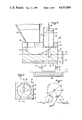
- FIG. 2 is a diagrammatic section view of an embodiment of a filling station
- FIG. 3 is a diagrammatic section view on a line II--II in FIG. 2, with the volumetric dispenser's feed hopper being omitted;
- FIG. 6 is a section through an example of the resilient means interposed between the cam and a volumetric dispenser.
- the calculating and storage unit 60 e.g. a microprocessor, continuously compares the weight of the material contained in the receptacle with the desired weight, and when the desired weight is reached, it causes receptacle filling to be stopped.
- the filled receptacle then leaves the carrousel 3, either tangentially thereto on conveyor means 25, or else in a preferred direction, e.g. parallel to the conveyor 1, by means of a second distributer star 4 leading to a conveyor 5.
- FIG. 2 is a diagrammatic section through an embodiment of a filling station.
- Each filling station is situated on the rotary carrousel and comprises: an electronic balance 36; means 38 for centering a receptacle 39; a feed hopper 12 for material to be packaged; a volumetric dispenser 37 comprising a piston 28 fitted with sealing means 29, a cylinder 13 in which the piston 28 slides, and a rod 33 for actuating the piston 28; and a tap 14 comprising a body 19 and a cylindrical plug 18 mounted to rotate in the body 19.
- the cylindrical plug 18 fills the bore of the body 19 and is free to rotate about the axis 27. It includes: a hollowed out portion 15 which serves, in a predetermined position of the plug relative to the body, to put the hopper duct 24 into communication with the dispenser duct 26; a dispensing duct 17 which is not in communication with the hollowed out portion 15 and which serves, in a different predetermined position of the plug relative to the body, to put the dispenser 37 in communication with the lower duct 30 through the body 19; and a control lever 20 by which the plug 18 may be rotated relative to the body 19.
- Suitable actuator means 61 (FIG. 4) which may be electrically, pneumatically or otherwise driven, act on the lever 20 on instructions from the calculating and storage unit 60.
- the plug 18 When a filling station is between the points 10 and 7 shown in FIG. 1, the plug 18 is placed as shown in FIG. 2 so that the hollowed out portion 15 puts the hopper into communication with the dispenser. When a filling station is between the point 7 and the point somewhere between the points 8 and 9 at which filling is stopped, the plug 18 is placed so that the duct 17 is aligned with the ducts 26 and 30, thereby putting the volumetric dispenser in communication with a receptacle 39.
- FIG. 4 is a diagrammatic development of a cam showing the cam controlling operation of two filling stations. It must be understood that in practice this cam is not developed as shown, but rather is wrapped round the periphery of a cylinder having the same axis as the carrousel. Further it should be understood that it may control as many filling stations as is convenient, which, in practice, will normally be more than two.
- the cam 34 is fixed relative to the rotation of the carrousel 3 on which the filling stations are mounted. It controls the operation of each filling station by guiding a cam-follower wheel 32 which is fixed to the piston rod 33.
- Resilient means 40 exert a force between the end of each rod 33 and a vertically fixed point 41 on the carrousel.
- the resilient means 40 act in compression and keep the wheels 32 in contact with the cam 34, thereby ensuring that the wheels follow the falling portions of the cam. They also have a second function.
- the calculation and storage unit 60 determines that receptacle filling should stop, it stops the filling by closing the tap 14. If the cam follower wheel 32 were constrained to follow the cam all the way down, eg.
- the resilient force exerted by the means 40 is designed to be sufficient to overcome the resistance of material as it is dispensed through the ducts 26, 17 and 30, but less than the resistance applied to the piston 28 when the tap 14 is closed, so that the unused portion of the piston stroke is absorbed by the resilient means 40 after the tap is closed and with some excess product remaining in the dispenser.
- the wheel 32 looses contact with the falling ramp at the point where filling stops, and regains contact at the point on the rising ramp of the cam which is at the same level.
- the resilient means 40 constitute a safety margin in the event of some kinds of jamming. Since the cam-follower wheel can leave the cam if necessary, many kinds of possible damage are avoided.
- the calculating and storage unit 60 stores the coordinates of the filling stop point and verifies that it lies on a portion of the ramp 343. If for any reason the stop point begins to drift and approach either the point 8 or the point 9 by more than some tolerated amount of drift, the calculating and storage unit modifies the slope of the portion of the ramp 341 in such a direction as to tend to return the stop point to the middle of the allowed range.
- FIG. 6 is a section through another example of resilient means interposed between the cam 34 and the rod 33 of the piston in each volumetric dispenser.
- the piston 28 of the volumetric dispenser 37 is surmounted by a cylindrical portion 47 having a bore for guiding the end of the rod 33.
- the rod 33 includes a vertical slot 48. The slotted end of the rod is inserted in the bore of the cylindrical portion 47 in which it is free to slide vertically between two end positions defined by a horizontal pin 50 engaged in the vertical slot 48.
- a ring 49 is fitted to the rod 33 by a second pin 51.
- the ring has a shoulder in which it receives a compression spring 52 acting between the piston 28 and the ring to urge the rod 33 away from the piston.
- the spring 52 is mounted around the rod 33.
- This arrangement of resilient means is compatible with the use of a rail running parallel to the cam 34 and thus constraining the cam-follower wheel to follow the cam at all times.
Landscapes
- Engineering & Computer Science (AREA)
- Mechanical Engineering (AREA)
- Basic Packing Technique (AREA)
- Weight Measurement For Supplying Or Discharging Of Specified Amounts Of Material (AREA)
- Filling Of Jars Or Cans And Processes For Cleaning And Sealing Jars (AREA)
- Supplying Of Containers To The Packaging Station (AREA)
- Container Filling Or Packaging Operations (AREA)
- Auxiliary Devices For And Details Of Packaging Control (AREA)
- Processing And Handling Of Plastics And Other Materials For Molding In General (AREA)
Applications Claiming Priority (2)
| Application Number | Priority Date | Filing Date | Title |
|---|---|---|---|
| FR8318417A FR2555132B1 (fr) | 1983-11-18 | 1983-11-18 | Procede de remplissage d'un recipient d'une quantite determinee de produit |
| FR8318417 | 1983-11-18 |
Publications (1)
| Publication Number | Publication Date |
|---|---|
| US4635688A true US4635688A (en) | 1987-01-13 |
Family
ID=9294298
Family Applications (1)
| Application Number | Title | Priority Date | Filing Date |
|---|---|---|---|
| US06/671,667 Expired - Fee Related US4635688A (en) | 1983-11-18 | 1984-11-15 | Method and apparatus for monitoring and controlling production line filling of receptacles with a predetermined weight of variable density material |
Country Status (10)
| Country | Link |
|---|---|
| US (1) | US4635688A (de) |
| EP (1) | EP0143692B1 (de) |
| JP (1) | JPH0627662B2 (de) |
| AT (1) | ATE33469T1 (de) |
| BR (1) | BR8405869A (de) |
| CA (1) | CA1232883A (de) |
| DE (1) | DE3470401D1 (de) |
| ES (1) | ES8601046A1 (de) |
| FR (1) | FR2555132B1 (de) |
| ZA (1) | ZA848851B (de) |
Cited By (9)
| Publication number | Priority date | Publication date | Assignee | Title |
|---|---|---|---|---|
| US4817683A (en) * | 1987-07-01 | 1989-04-04 | Laub Engineering Corporation | Adjustable automatic accurate container filling machine |
| US4830068A (en) * | 1986-09-04 | 1989-05-16 | Benz & Hilgers Gmbh | Device for the simultaneous quantitative regulated filling of liquid or soft plasticized substances, such as butter, margarine, pastes or the like by means of nozzles into adjacently arranged containers |
| US5159959A (en) * | 1989-11-17 | 1992-11-03 | Benz & Hilgers Gmbh | Double feedback packing system for pasty material |
| US5273082A (en) * | 1991-05-27 | 1993-12-28 | Seitz Enzinger Noll Maschinenbau Aktiengesellschaft | Method and apparatus for filling containers |
| US5280815A (en) * | 1992-05-05 | 1994-01-25 | Prc | Product filling machine |
| US5356041A (en) * | 1993-03-23 | 1994-10-18 | Fluid Management Limited Partnership | Dispensing apparatus having improved valving |
| US5921759A (en) * | 1997-10-14 | 1999-07-13 | Sandeep Khan | Liquid metering piston pump and valves capable of being cleaned and sterilized without disassembly |
| US5971037A (en) * | 1996-03-04 | 1999-10-26 | Mg2 S.P.A. | Method of controlling the weight of granulated products on multiple metering machines, and metering machine implementing such a method |
| US6390330B2 (en) * | 2000-01-13 | 2002-05-21 | Robert Bosch Gmbh | Apparatus for metering and dispensing powder into hard gelatin capsules or the like |
Citations (14)
| Publication number | Priority date | Publication date | Assignee | Title |
|---|---|---|---|---|
| US1726297A (en) * | 1923-04-23 | 1929-08-27 | Hansen Canning Machinery Corp | Apparatus for treating kraut |
| US2280614A (en) * | 1939-01-17 | 1942-04-21 | Harry D Ayars | Filling machine |
| US2321994A (en) * | 1939-12-11 | 1943-06-15 | Frank D Chapman | Receptacle filler |
| US2961013A (en) * | 1958-04-28 | 1960-11-22 | Texaco Inc | Positive displacement type fluid filling machine having automatic cam track adjustingmeans and method of filling |
| US3189062A (en) * | 1961-07-26 | 1965-06-15 | Cherry Burrell Corp | Filling machine |
| US3240146A (en) * | 1962-11-20 | 1966-03-15 | Swift & Co | Controls for ham pumping |
| GB1023469A (en) * | 1962-12-13 | 1966-03-23 | Holstein & Kappert Maschf | Apparatus for controlling pumps for filling containers with liquid |
| US3570558A (en) * | 1967-06-14 | 1971-03-16 | Maurice D L Lachaussee | Continuously rotating filling machine having a volumetric metering device for pulverulent or granular material |
| US3955243A (en) * | 1973-10-10 | 1976-05-11 | Rieter Machine Works, Ltd. | Apparatus for receiving a silver can and for controlling the quantity of material deposited therein |
| US4060106A (en) * | 1976-05-21 | 1977-11-29 | Kewpie Kabushiki Kaisha | Method and system for preventing containerless discharging of filling material in container filling apparatus |
| US4060109A (en) * | 1976-05-14 | 1977-11-29 | Kewpie Kabushiki Kaisha | Filling quantity regulating system in container filling apparatus |
| US4244404A (en) * | 1979-02-12 | 1981-01-13 | Domain Industries, Inc. | Rotary piston filler |
| US4337802A (en) * | 1980-09-30 | 1982-07-06 | Velasco Scale Company, Inc. | Method and apparatus for liquid filling of containers |
| US4446674A (en) * | 1980-02-05 | 1984-05-08 | Dai Nippon Insatsu Kabushiki Kaisha | Contamination-free apparatus for filling spouted bags with a fluid |
Family Cites Families (2)
| Publication number | Priority date | Publication date | Assignee | Title |
|---|---|---|---|---|
| US2925835A (en) * | 1958-03-31 | 1960-02-23 | Kartridg Pak Machine Co | Automatic filling and weight checking machine |
| FR2493800A1 (fr) * | 1980-11-13 | 1982-05-14 | Serac Sa | Procede et dispositif de controle de materiaux de remplissage dans une machine de remplissage a dosage ponderal |
-
1983
- 1983-11-18 FR FR8318417A patent/FR2555132B1/fr not_active Expired
-
1984
- 1984-11-09 EP EP84402269A patent/EP0143692B1/de not_active Expired
- 1984-11-09 DE DE8484402269T patent/DE3470401D1/de not_active Expired
- 1984-11-09 AT AT84402269T patent/ATE33469T1/de not_active IP Right Cessation
- 1984-11-13 ZA ZA848851A patent/ZA848851B/xx unknown
- 1984-11-15 US US06/671,667 patent/US4635688A/en not_active Expired - Fee Related
- 1984-11-16 BR BR8405869A patent/BR8405869A/pt not_active IP Right Cessation
- 1984-11-16 CA CA000468079A patent/CA1232883A/en not_active Expired
- 1984-11-16 ES ES537739A patent/ES8601046A1/es not_active Expired
- 1984-11-17 JP JP59243140A patent/JPH0627662B2/ja not_active Expired - Lifetime
Patent Citations (14)
| Publication number | Priority date | Publication date | Assignee | Title |
|---|---|---|---|---|
| US1726297A (en) * | 1923-04-23 | 1929-08-27 | Hansen Canning Machinery Corp | Apparatus for treating kraut |
| US2280614A (en) * | 1939-01-17 | 1942-04-21 | Harry D Ayars | Filling machine |
| US2321994A (en) * | 1939-12-11 | 1943-06-15 | Frank D Chapman | Receptacle filler |
| US2961013A (en) * | 1958-04-28 | 1960-11-22 | Texaco Inc | Positive displacement type fluid filling machine having automatic cam track adjustingmeans and method of filling |
| US3189062A (en) * | 1961-07-26 | 1965-06-15 | Cherry Burrell Corp | Filling machine |
| US3240146A (en) * | 1962-11-20 | 1966-03-15 | Swift & Co | Controls for ham pumping |
| GB1023469A (en) * | 1962-12-13 | 1966-03-23 | Holstein & Kappert Maschf | Apparatus for controlling pumps for filling containers with liquid |
| US3570558A (en) * | 1967-06-14 | 1971-03-16 | Maurice D L Lachaussee | Continuously rotating filling machine having a volumetric metering device for pulverulent or granular material |
| US3955243A (en) * | 1973-10-10 | 1976-05-11 | Rieter Machine Works, Ltd. | Apparatus for receiving a silver can and for controlling the quantity of material deposited therein |
| US4060109A (en) * | 1976-05-14 | 1977-11-29 | Kewpie Kabushiki Kaisha | Filling quantity regulating system in container filling apparatus |
| US4060106A (en) * | 1976-05-21 | 1977-11-29 | Kewpie Kabushiki Kaisha | Method and system for preventing containerless discharging of filling material in container filling apparatus |
| US4244404A (en) * | 1979-02-12 | 1981-01-13 | Domain Industries, Inc. | Rotary piston filler |
| US4446674A (en) * | 1980-02-05 | 1984-05-08 | Dai Nippon Insatsu Kabushiki Kaisha | Contamination-free apparatus for filling spouted bags with a fluid |
| US4337802A (en) * | 1980-09-30 | 1982-07-06 | Velasco Scale Company, Inc. | Method and apparatus for liquid filling of containers |
Cited By (9)
| Publication number | Priority date | Publication date | Assignee | Title |
|---|---|---|---|---|
| US4830068A (en) * | 1986-09-04 | 1989-05-16 | Benz & Hilgers Gmbh | Device for the simultaneous quantitative regulated filling of liquid or soft plasticized substances, such as butter, margarine, pastes or the like by means of nozzles into adjacently arranged containers |
| US4817683A (en) * | 1987-07-01 | 1989-04-04 | Laub Engineering Corporation | Adjustable automatic accurate container filling machine |
| US5159959A (en) * | 1989-11-17 | 1992-11-03 | Benz & Hilgers Gmbh | Double feedback packing system for pasty material |
| US5273082A (en) * | 1991-05-27 | 1993-12-28 | Seitz Enzinger Noll Maschinenbau Aktiengesellschaft | Method and apparatus for filling containers |
| US5280815A (en) * | 1992-05-05 | 1994-01-25 | Prc | Product filling machine |
| US5356041A (en) * | 1993-03-23 | 1994-10-18 | Fluid Management Limited Partnership | Dispensing apparatus having improved valving |
| US5971037A (en) * | 1996-03-04 | 1999-10-26 | Mg2 S.P.A. | Method of controlling the weight of granulated products on multiple metering machines, and metering machine implementing such a method |
| US5921759A (en) * | 1997-10-14 | 1999-07-13 | Sandeep Khan | Liquid metering piston pump and valves capable of being cleaned and sterilized without disassembly |
| US6390330B2 (en) * | 2000-01-13 | 2002-05-21 | Robert Bosch Gmbh | Apparatus for metering and dispensing powder into hard gelatin capsules or the like |
Also Published As
| Publication number | Publication date |
|---|---|
| FR2555132A1 (fr) | 1985-05-24 |
| ATE33469T1 (de) | 1988-04-15 |
| EP0143692A1 (de) | 1985-06-05 |
| ES537739A0 (es) | 1985-10-16 |
| DE3470401D1 (en) | 1988-05-19 |
| CA1232883A (en) | 1988-02-16 |
| FR2555132B1 (fr) | 1986-03-28 |
| JPH0627662B2 (ja) | 1994-04-13 |
| EP0143692B1 (de) | 1988-04-13 |
| ES8601046A1 (es) | 1985-10-16 |
| ZA848851B (en) | 1985-06-26 |
| JPS60155927A (ja) | 1985-08-16 |
| BR8405869A (pt) | 1985-09-17 |
Similar Documents
| Publication | Publication Date | Title |
|---|---|---|
| US4635688A (en) | Method and apparatus for monitoring and controlling production line filling of receptacles with a predetermined weight of variable density material | |
| US3887110A (en) | Dispensing methods and apparatus | |
| KR900006602B1 (ko) | 액체충전방법 및 장치 | |
| US5273082A (en) | Method and apparatus for filling containers | |
| US2925835A (en) | Automatic filling and weight checking machine | |
| US6148877A (en) | Fluid filling system with fill time optimization | |
| JPH04128184A (ja) | 容器の中に流体、ジェラチン、腐食性若しくは粘着性の生成物、又は研摩剤の懸濁液を充満させる方法及びその方法を実施する機械装置 | |
| EP0334537B1 (de) | Gerät zum Füllen vom Boden aus | |
| US4635689A (en) | Method and apparatus for monitoring and controlling the filling of receptacles with a determined weight of material | |
| NO178246B (no) | Styresystem for en anordning som har frem og tilbakegående lineær bevegelse eller intermittent bevegelse | |
| US3613331A (en) | Feeding mechanism for a container filling machine | |
| US2121065A (en) | Formation and packaging of material | |
| US3477617A (en) | Indexing type of filling machine with bottom flap valve | |
| US3557847A (en) | Dispensing apparatus for particulate matter | |
| US3529399A (en) | Apparatus for automatic filling and capping of liquid containers having semi-rigid walls | |
| US4582101A (en) | Device for filling a receptacle | |
| US2922444A (en) | Pocket fill can | |
| US3095055A (en) | Automatic filling and weighing device for successive containers | |
| US3195589A (en) | Continuous-flow filling apparatus | |
| US3330310A (en) | Carton filling apparatus | |
| US1570151A (en) | Can-filling machine | |
| US5092413A (en) | Method and apparatus for high speed weigh fill | |
| SU806782A1 (ru) | Устройство дл затаривани губчатогоТиТАНА | |
| SU598796A1 (ru) | Устройство дл дозировани в консервные банки жидких продуктов | |
| KR20000015305A (ko) | 자동감귤계수방법 및 그 장치 |
Legal Events
| Date | Code | Title | Description |
|---|---|---|---|
| AS | Assignment |
Owner name: ETABLISSEMENTS A. BERTAUD, 11 A 15, 6EME RUE Z.1. Free format text: ASSIGNMENT OF ASSIGNORS INTEREST.;ASSIGNOR:GRAFFIN, ANDRE JEAN-JACQUES;REEL/FRAME:004605/0301 Effective date: 19850121 |
|
| FEPP | Fee payment procedure |
Free format text: PAYOR NUMBER ASSIGNED (ORIGINAL EVENT CODE: ASPN); ENTITY STATUS OF PATENT OWNER: SMALL ENTITY |
|
| FPAY | Fee payment |
Year of fee payment: 4 |
|
| REMI | Maintenance fee reminder mailed | ||
| LAPS | Lapse for failure to pay maintenance fees | ||
| FP | Lapsed due to failure to pay maintenance fee |
Effective date: 19950118 |
|
| STCH | Information on status: patent discontinuation |
Free format text: PATENT EXPIRED DUE TO NONPAYMENT OF MAINTENANCE FEES UNDER 37 CFR 1.362 |