US4612865A - Apparatus for the combustion of solid fuels - Google Patents
Apparatus for the combustion of solid fuels Download PDFInfo
- Publication number
- US4612865A US4612865A US06/754,425 US75442585A US4612865A US 4612865 A US4612865 A US 4612865A US 75442585 A US75442585 A US 75442585A US 4612865 A US4612865 A US 4612865A
- Authority
- US
- United States
- Prior art keywords
- ash
- combustion chamber
- wall
- end wall
- drive shaft
- Prior art date
- Legal status (The legal status is an assumption and is not a legal conclusion. Google has not performed a legal analysis and makes no representation as to the accuracy of the status listed.)
- Expired - Fee Related
Links
Images


Classifications
-
- F—MECHANICAL ENGINEERING; LIGHTING; HEATING; WEAPONS; BLASTING
- F23—COMBUSTION APPARATUS; COMBUSTION PROCESSES
- F23G—CREMATION FURNACES; CONSUMING WASTE PRODUCTS BY COMBUSTION
- F23G5/00—Incineration of waste; Incinerator constructions; Details, accessories or control therefor
- F23G5/32—Incineration of waste; Incinerator constructions; Details, accessories or control therefor the waste being subjected to a whirling movement, e.g. cyclonic incinerators
-
- F—MECHANICAL ENGINEERING; LIGHTING; HEATING; WEAPONS; BLASTING
- F23—COMBUSTION APPARATUS; COMBUSTION PROCESSES
- F23G—CREMATION FURNACES; CONSUMING WASTE PRODUCTS BY COMBUSTION
- F23G7/00—Incinerators or other apparatus for consuming industrial waste, e.g. chemicals
- F23G7/10—Incinerators or other apparatus for consuming industrial waste, e.g. chemicals of field or garden waste or biomasses
-
- F—MECHANICAL ENGINEERING; LIGHTING; HEATING; WEAPONS; BLASTING
- F23—COMBUSTION APPARATUS; COMBUSTION PROCESSES
- F23J—REMOVAL OR TREATMENT OF COMBUSTION PRODUCTS OR COMBUSTION RESIDUES; FLUES
- F23J1/00—Removing ash, clinker, or slag from combustion chambers
- F23J1/06—Mechanically-operated devices, e.g. clinker pushers
-
- F—MECHANICAL ENGINEERING; LIGHTING; HEATING; WEAPONS; BLASTING
- F23—COMBUSTION APPARATUS; COMBUSTION PROCESSES
- F23M—CASINGS, LININGS, WALLS OR DOORS SPECIALLY ADAPTED FOR COMBUSTION CHAMBERS, e.g. FIREBRIDGES; DEVICES FOR DEFLECTING AIR, FLAMES OR COMBUSTION PRODUCTS IN COMBUSTION CHAMBERS; SAFETY ARRANGEMENTS SPECIALLY ADAPTED FOR COMBUSTION APPARATUS; DETAILS OF COMBUSTION CHAMBERS, NOT OTHERWISE PROVIDED FOR
- F23M5/00—Casings; Linings; Walls
- F23M5/08—Cooling thereof; Tube walls
- F23M5/085—Cooling thereof; Tube walls using air or other gas as the cooling medium
Definitions
- the invention relates to a cyclone furnace for solid fuels, comprising a generally cylindrical combustion chamber which is closed at one end and provided with an opening for supplying combustion air and fuel, said opening being directed essentially tangentially.
- the apparatus is especially intended for the combustion of biomass, such as harvest refuse.
- the scraping means and the associated equipment must be located and designed in such a way that they do not disturb the combustion process or the currents of air and flue gases, or, if such disturbance occurs, that the disturbance is such that the combustion and/or the ash deposition are not considerably impaired.
- the scraping means and the associated equipment in themselves must be able to resist the strain which is inflicted upon them in the combustion area, and in case ash and slag are deposited on the scraping means, this shall not either impair their function.
- the object of the invention is to provide an improved apparatus for the combustion of biomass and other solid fuels which may be suspended in a flow of air.
- an object is to provide an improved system for separating slag and ashes.
- the combustion chamber is essentially horizontal, according to a first characteristic of the invention, while fuel and air are added tangentially at the outlet end of the combustion chamber. This brings about the effect that the ash is accumulated in the inner part of the combustion chamber during the combustion process.
- the combustion chamber is provided at its inner end with means for scraping, intended to scrape loose ashes and slag from the walls and to transport the loosened material to an area at the cylindrical bottom of the combustion chamber, where there is provided an opening for the discharge of ashes and slag. Near this opening, there is arranged a hatch at a certain level below the inside of the cylindrical bottom of the combustion chamber, a space thus being created into which may be put a certain amount of ashes and slag which has been scraped off the walls of the combustion chamber and has been brought to this receiving space by said scraping means.
- this hatch is the first hatch of an ash discharge sluice with a sluice volume which is greater than the volume of said ash receiving space, so that the sluice chamber is able to accomodate all the ashes and slag contained in the upper space when the upper sluice hatch opens.
- the sluice is part of a discharge conduit, which brings the ash from the discharge opening to an ash bin or the like.
- the sluice is a mechanical sluice comprising said first and second hatches and controlling means for the opening and shutting of the two hatches in said order.
- a water trap may be provided in the discharge conduit.
- the scraping means are designed both to scrape loose ash and slag from those parts of the walls of the combustion chamber where most of the combustion process takes place and to bring the ash products to the discharge opening and to "scrape them down" into said upper ash receiving space.
- the scraping means comprise at least one scraping unit with a scraper which is flush against the cylindrical wall and preferably extends helically along the inside of the cylindrical wall, intended to move loosened ash and slag toward the ash receiving space near the bottom wall.
- the two scraping units which may well be integrated, but which are preferably separate units, are preferably mounted on a drive shaft, which extends through the end wall and preferably also comprises a part which extends into the combustion chamber approximately the same distance as the axial length of that scraping unit which is intended to scrape the inside of the cylindrical wall of the combustion chamber.
- All scraping means are water-cooled so as to withstand the high temperature in the combustion chamber. This temperature may vary between 800° and 1200° C. depending on the moisture content and the air-to-fuel ratio. By virtue of the possibility according to the invention of handling both solid ash and more or less liquid, slag-like ash, that temperature may be chosen which corresponds to the optimal air/fuel ratio, which permits a relatively low excess of air and hence a high combustion temperature.
- Another object of the invention is to provide a cyclone furnace which is able to perform at very high temperatures, which enhances efficience and a very small emission of unburnt products with the flue gases.
- the cyclone furnace according to yet another aspect of the invention is characterized in that at least its cylindrical mantle is covered with air conduits. The air of combustion is led through these conduits, thus being pre-heated before entering the combustion chamber. The heat required to accomplish this pre-heating is transmitted through the wall of the combustion chamber, and another effect is that there is no need to insulate the external wall.
- the air of combustion enter the combustion chamber near the end wall and from there to flow helically along the mantle, so that it is gradually heated to a higher and higher temperature, before being led into the combustion chamber near the orifice of the cyclone furnace.
- a choke is provided at the entrance to the combustion chamber so as to raise the air velocity considerably. This makes it possible to keep the air velocity comparatively low as long as the air is circulating along the chamber wall, the pressure drop consequently being low and the necessary fan power small.
- the end wall also be covered by air conduits, through which flows air which has been branched off from the first turn of that air conduit which runs on the outside of the mantle.
- FIG. 1 is a plan view of an apparatus comprising a furnace in accordance with the invention, said furnace being used as a heat source for the drying of wood chips in a rotating chips dryer;
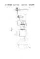
- FIG. 2 is an elevation of the apparatus of FIG. 1, as viewed according to the indication II--II of FIG. 1;
- FIG. 3 is an end elevation of the same apparatus, as viewed according to the indication III--III of FIG. 2;
- FIG. 4 is an elevation of a cyclone furnace according to the invention.
- FIG. 5 is a horizontal axial section of the furnace of FIG. 4, taken along the line V--V;
- FIG. 6 is an end elevation according to VI--VI of the furnace of FIG. 4, including certain parts not illustrated in FIGS. 4 and 5;
- FIG. 7 is a vertical axial section through the head of the furnace and some adjoining parts of its cylindrical part showing the scraping means and certain elements connected to the outside of the head of the furnace;
- FIG. 8 is a view of the scraping means according to the indication VIII--VIII of FIG. 7;
- FIG. 9 is a sectional view perpendicular to the axial direction showing an ash discharge sluice and the controlling means for the sluice hatches.
- FIG. 10 is a false vertical section of the outlet end of the furnace, illustrating the arrangement of the fuel and air feed.
- a cyclone furnace according to the invention is generally designated by numeral 1.
- the furnace is part of a drying plant for wood chips and functions as a central heat generator.
- the flue gases from the furnace 1 have a temperature exceeding 1000° C. and are therefore mixed with cold air in a mixing chamber 2 to acquire a temperature of not more than 250° C. before being led into a rotating chips dryer 3.
- the furnace 1 is fed with solid fuel, such as pellets of straw, from a silo 4 by a feed worm 5 and a feed conduit 6 via a fan 7, which feeds the fuel together with a certain amount of air into the furnace, where it is injected tangentially near, but not adjacent, the outlet of the furnace.
- the entire apparatus is placed on a plate 9, which also supports a fan 10 for combustion air.
- This fan feeds combustion air to the cyclone furnace 1 through a conduit 11 for combustion air, which is connected tangentially to the rear part of the air-cooled mantle of the cyclone furnace 1.
- An ash and slag discharge conduit 12 is connected below the rear part of the furnace 1, see FIG. 3.
- a water trap 13 may be arranged below the conduit 12, with the additional purpose of extinguishing slag and ash possibly still aglow, before the slag and ash is transported to a container 16 via an ash discharge worm 14 and a chute 15.
- scraping means powered and cooled by a device 17 at the head 18 of the furnace.
- the head 18 may be loosened and swung aside on hinges 19.
- a cylindrical combustion chamber 21 is defined by a cylindrical combustion chamber wall 22 of refractory material, an end wall 23, also made of refractory material, and a connective piece 24 with an outlet 25 for flue gases with a temperature exceeding 1000° C. and a velocity of 70-90 m/s.
- the connective piece 24 is also made of refractory material. Possibly, this piece could be provided with cooling circuits in the ceramic material near the outlet 25.
- the connective piece 24 is mounted to the furnace 1 by means of screws and may thus be loosened in case of replacement or repair.
- the furnace 1 may be adapted to different objects, so that a furnace of the same basic configuration may be used for different applications.
- the refractory material of the furnace 1 is thickest at the end wall 23 and the inner part of the cylindrical wall 22 of the combustion chamber, where the highest temperatures are encountered.
- the cylindrical combustion chamber wall 22 narrows toward the connective piece 24, which in this embodiment is not water-cooled and therefore has a large wall thickness close to the outlet 25.
- the air channels 28 on the inner mantle 26 run three turns 28a, 28b, 28c, around the periphery of the mantle.
- first turns 28a, 28b there is a transverse wall, forcing the air current in the channel to enter the next turn via a connection between the adjacent turns, such as between the turns 28a and 28b and between 28b and 28c, respectively.
- the combustion air conduit 11 see FIGS. 1-3, is connected to an air inlet conduit 30, which is tangentially connected to the inner end of the air channel 28, specifically to the first turn 28a of this helix.
- Some of the combustion air flow is diverted from the air inlet conduit 30 through a conduit 31, which extends back to the head wall 18, where it opens into the inner turn 29a of a helical air channel 29.
- This air channel 29 continues tangentially at the end of its outer turn 33a, whence it continues with a return conduit 34 to the air channel 28 on the outside of the mantle.
- the "last turn” 28c of the channel 28 is not provided with any transverse wall.
- the air therefore is free to rotate within this final part before entering two air inlet openings 33a and 33b through the mantle 26 and the cylindrical combustion chamber wall 22 directly inside the connective piece 24.
- Each of the air inlet openings 33a and 33b houses a throttle 34, which constitutes one of the arms of a lever, which turns about a fulcrum 35.
- the second lever arm 36 is provided at its end with a counter-weight 37, or a spring 37', biasing the throttle 34 toward the closed position.
- the air velocity is raised from about 20 m/s in the channel 28 to between 80 and 90 m/s in the inlet openings 33a and 33b. It is possible to replace the counter-balanced throttles by inclined sliding doors, controlled by setting motors, to guarantee the desired air flow at all times. In this manner, the flow may be controlled with a greater accuracy and may be adapted to the varying demands so that the air velocity is always suitable and hence the cyclone effect in the combustion chamber 21 is always optimal.
- the fuel being fed into the combustion chamber 21 through the opening 38, via the feed conduit 8, which extends through the air channel 28 and the mantle 26, is snatched by the passing air stream from the air inlets 33a, 33b and is fed further into the combustion chamber 21 along the cylindrical combustion chamber wall 22.
- the fuel being fed does not come into contact with the hot flue gases flowing centrally out of the combustion chamber 21 through the outlet 25.
- an oil burner which in FIG. 4 has been symbolically designated 40.
- This oil burner may be of a conventional design and provided with an oil spray nozzle and an electric spark plug. These parts are arranged within a pipe 41, which extends through the air channel 28, the mantle 26, and the combustion chamber wall 22.
- the primary purpose of the oil burner is to start up the furnace 1.
- a second pipe 42 be arranged coaxially outside that pipe which contains the oil burner 40, and in the clearance between the two pipes 41 and 42 one or several oil feed 43 pipes may be arranged, so that more oil may be sprayed into the combustion chamber 21, there to burn, if for some reason there should be fed too little solid fuel into the furnace.
- the oil burner 40 and said pipe and oil spray nozzles are arranged at the upper part of the combustion wall 22 so as not to be stopped-up by slag and ashes scraped loose from the walls.
- the furnace 1 described above functions as follows. During the starting-up process air is blown in through the openings 33a, 33b. Oil is supplied to the burner 40 which is ignited electrically according to prior art. Then, granular solid fuel, preferably granular biomass, is entered through the fuel feed opening 38. When this fuel is aflame, the oil supply is closed and the flow of air and fuel is regulated as desired within the working limits of the furnace. The air of combustion, flowing at a high speed tangentially through the inlets 33a, 33b pulls that fuel along which is fed through the fuel feed opening 38, the mixture of air and fuel then following the inside of the cylindrical combustion chamber wall 22 along a track composed of both circular and axial motion, in other words helically, toward the furnace head 18.
- the fuel continues to rotate in the vicinity of the end wall 23, until it has been burnt up fully, while the flue gases move centrally along the central axis of the furnace 1 toward the outlet 25 and out therethrough.
- ash particles are separated from the flue gases, which run axially back through the outlet 25.
- the flue gases mainly consist of carbon monoxide and water vapour.
- the ash is deposited on the walls of the combustion chamber 21, mainly on the end wall 23 and the adjacent parts of the cylindrical combustion chamber wall 22.
- the ash may be solid or more or less liquid, i.e. slag-like, depending on the temperature and the chemical composition of the fuel. These conditions may vary.
- the ash discharge device which must be able to loosen the ash efficiently from the walls and to transport it to an ash discharge opening.
- the equipment must be very robust. At the same time it must not interfere too much with the gas flow conditions in the innermost part of the combustion chamber 21, where the fuel is to whirl about, until it has been burnt up fully.
- the scrapers must withstand the high temperature inside the combustion chamber. The way to meet these almost incompatible demands will be disclosed in the following, with reference also to FIGS. 7 and 8.
- first scraping unit 45 comprising a first scraper 46 to scrape the end wall 23, and a second scraping unit with a second scraper 48 to scrape the cylindrical combustion chamber wall 22 in the vicinity of the end wall 23.
- the two scrapers 46 and 48 are mounted on a common shaft 49, extending through a bore 50 in the end wall 23.
- the bore 50 is lined with a thin sheet metal lining 51, the inner diameter of which is slightly larger than the outer diameter of the shaft 49, a small clearing 52 thus being created between the lining 51 and the shaft 49.
- the shaft 49 extends through this plate also and through a sealing muff 54, coaxially arranged on the outside of the plate 53.
- a sealing muff 54 coaxially arranged on the outside of the plate 53.
- To the chamber 55 is connected a conduit 57 for cold air, through which cold air is entered into the chamber 55 under a pressure exceeding the pressure in the combustion chamber 21, and from there via the clearing 52 into the combustion chamber 21 to prevent flue gases from exiting the back way and damaging the transmission of the scraping units.
- a drive motor for turning the shaft 49 has been designated 58, see FIG. 5.
- This motor is placed on a pair of horizontal brackets 59 on the gable plate 53. These two brackets 59 also support a pair of bearing housings for the shaft bearings 61.
- the head 18 is attached to the cylindrical part of the furnace 1 by means of screws. After loosening these screws, the head 18 may be swung aside on the hinges 19, a possibility made use of when the scraping units are to be de-slagged or some other maintenance be done.
- the first scraping unit 45 comprises the said first scraper 46 and a strut 62 extending at an angle of 45 from the outer end of the scraper 46 to the outer end of a part 63 of the drive shaft, extending into the combustion chamber 21.
- the scraper 46 extends radially from the shaft 49 and the strut 62 is arranged in the same radial plane.
- the design of the second scraper 48 is more complex.
- the two struts for the scraper 48 viz. an outer strut 64 and an inner strut 65, are of complex design.
- the two struts 64, 65 thus first extend with arched parts 66, see FIG. 8, outwards from the free end of the shaft 49, from where the outer strut 64 continues with a straight part 67 toward the outer end ot the scraper 48, while the inner strut 65 continues with a straight part toward the inner part of the scraper 48.
- the form of the struts 64, 65 is useful for several reasons.
- the flow resistance is lowered, because the struts 64, 65 are bent along the direction of flow.
- the arched parts permit the scraper 48 to yield resiliently toward the centre, should it encounter some collection of ash or slag or some other obstruction which does not come loose directly. After passing the obstruction, the scraper may spring back into its original position. If the struts 64, 65 were directed purely radially instead, there would be a risk of the scraper 48 jamming, since the "apparent radius" would increase if the scraper were blocked.
- the hard metal reinforcements have been designated 69 and 70, respectively.
- the two scraping units 45 and 47 as well as the shaft 49 are made of pipes.
- An external pipe 71 extends through the entire transmission 72 outside the furnace all the way to the end of the shaft part 63 which extends into the combustion chamber 21.
- An inner pipe 72 ends flush with the rear edge of the first radial scraper 46, where the gap 73 between the two pipes is closed off by a ring seal 74. The other end of the two pipes is sealed by a common stopper 75.
- a cylindrical casing 76 for the supply of cooling water.
- This cooling water casing 76 is divided into two chambers, a first chamber 77 and a second chamber 78, a partition wall 79 separating the two chambers.
- the through-bores for the shaft 49 through the walls 79 and 80 have been sealed by O-rings.
- To the first chamber 77 is connected a supply conduit 81 for cooling water and from the other chamber 78 runs a cooling water return conduit 82.
- the first chamber 77 is connected to the gap 73 between the pipes 71 and 72 by four openings 83 and there are four corresponding holes 84 between the second chamber 78 and the pipe 72.
- the cooling water supplied from a feeding line via the cooling water conduit 81 pass the following channels and rooms in the order stated: the chamber 77, the connective opening 83, the gap 73 between the outer pipe 71 and the inner pipe 72 of the shaft 49, the first scraper 46, the strut 62, the scraper 48, the strut 65, the shaft part 63 extending into the combustion chamber 21, the inner pipe 72, the connective openings 84, the chamber 78, and finally the return conduit 82 from where it is discharged to an open drain.
- the ash and slag which is scraped loose from the end wall 23 and the cylindrical combustion chamber wall 22 by means of the scrapers 46 and 48 is continually fed by the scraper 48 to an ash discharge opening 87 in the bottom of the cylindrical combustion chamber wall 22 near the end wall 23.
- the distance from the end wall 23 is approximately equal to the axial width of the scraper 46.
- the ash discharge opening 87 has a surrounding metal pipe 88, which runs radially through the refractory combustion chamber wall 22. On the outside the pipe 88 is welded to the sheet metal mantle 26.
- the conduit 12 is onnected to a chute 15 over the container 16 via a possible water trap and an ash discharge worm.
- the tubular channel 90 is connected to the air channel 28 via a smaller opening 91. Through this opening 91, air flows into the tubular channel 90.
- an ash discharge sluice generally designated 92. This sluice comprises an upper hatch 93 and a lower hatch 94.
- the upper hatch 93 is water-cooled and may be slid in or out of the channel 90 by means of a pneumatic cylinder 102, not shown, see FIG. 6.
- a drawbar coupled to this pneumatic cylinder has been designated 95.
- the lower hatch 94 may be controlled by a second pneumatic cylinder 103 independently of the first pneumatic cylinder.
- a drawbar coupled to the lower hatch 94 has been designated 96.
- a lower ash wiper is designated 98.
- the wall 97' of the rim member 97 works as an upper ash wiper.
- the cooling water for the water-cooled parts of the ash discharge sluice 92 is led from a main supply line first into the upper hatch 93, inside which the water follows a meander path. Thence, the water flows through the upper rim member 97 and then through the lower ash wiper 98, before being led to a drain. Air, entering the channel 90 through the opening 91, flows upwards through holes 99 in the lower hatch 94, in order to burn up any possible unburnt fuel products 105, accumulating on this hatch, and the flue gases from this combustion find their way up around the upper ash hatch 93 via slits. As indicated in FIG. 9, the sluice chamber 100 is slightly larger than the space 101 in the channel 90 over the upper hatch 93.
- the upper ash wiper 97 is designed as a rim surrounding the discharge opening 87 and lining the space 101 over the upper hatch 93.
- This rim member 97 extends from just above the hatch 93 up to be flush with the inside of the cylindrical wall 22.
- As cooling water flows through the rim member 97 it will from all sides cool any material that is scraped down into the space 101. Hence any more or less viscous slag, which enters the space 101, will freeze and be brittle. This is important because it otherwise can block the discharge opening 87. Due to the cooling performed by the water cooled ash wiping rim 97 this is, however, efficiently prevented.
Landscapes
- Engineering & Computer Science (AREA)
- Mechanical Engineering (AREA)
- General Engineering & Computer Science (AREA)
- Environmental & Geological Engineering (AREA)
- Sustainable Energy (AREA)
- Life Sciences & Earth Sciences (AREA)
- Combustion & Propulsion (AREA)
- Sustainable Development (AREA)
- Chemical & Material Sciences (AREA)
- Gasification And Melting Of Waste (AREA)
- Feeding And Controlling Fuel (AREA)
- Devices And Processes Conducted In The Presence Of Fluids And Solid Particles (AREA)
- Fluidized-Bed Combustion And Resonant Combustion (AREA)
- Combustion Of Fluid Fuel (AREA)
- Incineration Of Waste (AREA)
- Solid-Fuel Combustion (AREA)
- Apparatus For Radiation Diagnosis (AREA)
- Crucibles And Fluidized-Bed Furnaces (AREA)
- Cyclones (AREA)
Applications Claiming Priority (2)
| Application Number | Priority Date | Filing Date | Title |
|---|---|---|---|
| SE8403865A SE454112B (sv) | 1984-07-26 | 1984-07-26 | Askutmatningsanordning |
| SE8403865 | 1984-07-26 |
Publications (1)
| Publication Number | Publication Date |
|---|---|
| US4612865A true US4612865A (en) | 1986-09-23 |
Family
ID=20356607
Family Applications (1)
| Application Number | Title | Priority Date | Filing Date |
|---|---|---|---|
| US06/754,425 Expired - Fee Related US4612865A (en) | 1984-07-26 | 1985-07-12 | Apparatus for the combustion of solid fuels |
Country Status (11)
| Country | Link |
|---|---|
| US (1) | US4612865A (de) |
| EP (1) | EP0170125B1 (de) |
| JP (1) | JPH06100321B2 (de) |
| AT (1) | ATE46958T1 (de) |
| AU (1) | AU573367B2 (de) |
| CA (1) | CA1263057A (de) |
| DE (1) | DE3573465D1 (de) |
| DK (1) | DK161163C (de) |
| ES (1) | ES8608655A1 (de) |
| NZ (1) | NZ212741A (de) |
| SE (1) | SE454112B (de) |
Cited By (7)
| Publication number | Priority date | Publication date | Assignee | Title |
|---|---|---|---|---|
| US4828577A (en) * | 1984-12-03 | 1989-05-09 | Markham Jr William M | Process for converting food sludges to biomass fuels |
| US5593301A (en) * | 1993-07-09 | 1997-01-14 | Alliant Techsystems, Inc. | Apparatus and method for burning energetic material |
| EP1281027A1 (de) * | 1999-12-22 | 2003-02-05 | Olivine (NZ) Limited | Müllverbrennungsanlage, verbrennungsverfahren und anlage zur wiedergewinnung von abfallenergie |
| EP1568948A2 (de) * | 2004-02-25 | 2005-08-31 | Achim Böhmer | Koaxial-Feststoffgranulat Heizanlage für automatischenBetrieb und Reinigung von Kessel und Rondellbrenner |
| US20060225424A1 (en) * | 2005-04-12 | 2006-10-12 | Zilkha Biomass Energy Llc | Integrated Biomass Energy System |
| US20080245052A1 (en) * | 2006-09-29 | 2008-10-09 | Boyce Phiroz M | Integrated Biomass Energy System |
| WO2016210435A1 (en) * | 2015-06-26 | 2016-12-29 | M-I L.L.C. | Cleaning system for a centrifugal dryer |
Families Citing this family (6)
| Publication number | Priority date | Publication date | Assignee | Title |
|---|---|---|---|---|
| JPH0523928Y2 (de) * | 1988-06-07 | 1993-06-18 | ||
| US4913066A (en) * | 1989-04-17 | 1990-04-03 | Westinghouse Electric Corp. | Rotary combustor having a material removal device |
| US5462429A (en) * | 1993-10-20 | 1995-10-31 | Praxair Technology, Inc. | Mechanical wiper for waste gas incinerator |
| JP5394961B2 (ja) * | 2010-03-26 | 2014-01-22 | 新日鉄住金エンジニアリング株式会社 | 冷却装置 |
| CN111974726B (zh) * | 2020-08-31 | 2021-08-27 | 合肥源康信息科技有限公司 | 一种急冷泵站出灰装置 |
| EP4296567A1 (de) | 2022-06-22 | 2023-12-27 | Julio Berkes S.A. | Verbrennungseinheit mit zyklonbrennkammer |
Citations (8)
| Publication number | Priority date | Publication date | Assignee | Title |
|---|---|---|---|---|
| US745642A (en) * | 1902-12-04 | 1903-12-01 | Hugh C Miller | Boiler scrapper and cleaner. |
| US2979000A (en) * | 1954-02-16 | 1961-04-11 | Babcock & Wilcox Co | Cyclone furnace unit and method of operating the same |
| US3199476A (en) * | 1963-04-30 | 1965-08-10 | Nettel Frederick | Apparatus and method for compound cyclone combustion of coal and other fuels |
| US3678870A (en) * | 1971-05-20 | 1972-07-25 | Air Preheater | Sludge burner |
| US3680503A (en) * | 1969-10-02 | 1972-08-01 | Gunnar Danielsson | Incinerator |
| US3777678A (en) * | 1971-06-14 | 1973-12-11 | Mac Millan Bloedel Ltd | Cyclonic type fuel burner |
| US3797413A (en) * | 1973-04-23 | 1974-03-19 | Gen Electric | Incinerator |
| US3831535A (en) * | 1973-11-02 | 1974-08-27 | Mill Conversion Contractor Inc | Wood waste burner system |
Family Cites Families (7)
| Publication number | Priority date | Publication date | Assignee | Title |
|---|---|---|---|---|
| DE1075781B (de) * | 1960-02-18 | Pintsch Bamag Aktiengesellschaft, Berlin | Austragevorrichtung für Schachtofen | |
| US3034164A (en) * | 1958-07-07 | 1962-05-15 | Atkinson Guy F Co | Boring machine |
| FR1333801A (fr) * | 1962-05-25 | 1963-08-02 | Wistra Ofenbau Gmbh | Procédé et dispositif pour l'exécution de réactions chimiques et de réactions physiques |
| GB1516402A (en) * | 1975-02-18 | 1978-07-05 | Pd Pollution Control Ltd | Incinerator |
| JPS5811210Y2 (ja) * | 1979-09-28 | 1983-03-02 | 昭和電線電纜株式会社 | 書類入れ兼用保安帽バツグ |
| FR2468836A1 (fr) * | 1979-10-31 | 1981-05-08 | Pillard Chauffage | Procedes et appareils pour bruler des combustibles solides divises de faible granulometrie |
| US4502991A (en) * | 1983-08-18 | 1985-03-05 | Wisconsin Alumni Research Foundation | 23,23-Difluoro-1α,25-dihydroxy-vitamin D3 |
-
1984
- 1984-07-26 SE SE8403865A patent/SE454112B/sv not_active IP Right Cessation
-
1985
- 1985-07-11 DE DE8585108660T patent/DE3573465D1/de not_active Expired
- 1985-07-11 EP EP85108660A patent/EP0170125B1/de not_active Expired
- 1985-07-11 AT AT85108660T patent/ATE46958T1/de not_active IP Right Cessation
- 1985-07-12 US US06/754,425 patent/US4612865A/en not_active Expired - Fee Related
- 1985-07-15 NZ NZ212741A patent/NZ212741A/en unknown
- 1985-07-22 DK DK332085A patent/DK161163C/da not_active IP Right Cessation
- 1985-07-25 CA CA000487486A patent/CA1263057A/en not_active Expired
- 1985-07-25 AU AU45350/85A patent/AU573367B2/en not_active Ceased
- 1985-07-26 JP JP60164238A patent/JPH06100321B2/ja not_active Expired - Lifetime
- 1985-07-26 ES ES545614A patent/ES8608655A1/es not_active Expired
Patent Citations (8)
| Publication number | Priority date | Publication date | Assignee | Title |
|---|---|---|---|---|
| US745642A (en) * | 1902-12-04 | 1903-12-01 | Hugh C Miller | Boiler scrapper and cleaner. |
| US2979000A (en) * | 1954-02-16 | 1961-04-11 | Babcock & Wilcox Co | Cyclone furnace unit and method of operating the same |
| US3199476A (en) * | 1963-04-30 | 1965-08-10 | Nettel Frederick | Apparatus and method for compound cyclone combustion of coal and other fuels |
| US3680503A (en) * | 1969-10-02 | 1972-08-01 | Gunnar Danielsson | Incinerator |
| US3678870A (en) * | 1971-05-20 | 1972-07-25 | Air Preheater | Sludge burner |
| US3777678A (en) * | 1971-06-14 | 1973-12-11 | Mac Millan Bloedel Ltd | Cyclonic type fuel burner |
| US3797413A (en) * | 1973-04-23 | 1974-03-19 | Gen Electric | Incinerator |
| US3831535A (en) * | 1973-11-02 | 1974-08-27 | Mill Conversion Contractor Inc | Wood waste burner system |
Cited By (12)
| Publication number | Priority date | Publication date | Assignee | Title |
|---|---|---|---|---|
| US4828577A (en) * | 1984-12-03 | 1989-05-09 | Markham Jr William M | Process for converting food sludges to biomass fuels |
| US5593301A (en) * | 1993-07-09 | 1997-01-14 | Alliant Techsystems, Inc. | Apparatus and method for burning energetic material |
| US5649325A (en) * | 1993-07-09 | 1997-07-15 | Alliant Techsystems, Inc. | Apparatus and method for burning energetic material |
| EP1281027A1 (de) * | 1999-12-22 | 2003-02-05 | Olivine (NZ) Limited | Müllverbrennungsanlage, verbrennungsverfahren und anlage zur wiedergewinnung von abfallenergie |
| EP1281027A4 (de) * | 1999-12-22 | 2004-07-07 | Olivine Nz Ltd | Müllverbrennungsanlage, verbrennungsverfahren und anlage zur wiedergewinnung von abfallenergie |
| EP1568948A2 (de) * | 2004-02-25 | 2005-08-31 | Achim Böhmer | Koaxial-Feststoffgranulat Heizanlage für automatischenBetrieb und Reinigung von Kessel und Rondellbrenner |
| EP1568948A3 (de) * | 2004-02-25 | 2006-06-07 | Achim Böhmer | Koaxial-Feststoffgranulat Heizanlage für automatischenBetrieb und Reinigung von Kessel und Rondellbrenner |
| US20060225424A1 (en) * | 2005-04-12 | 2006-10-12 | Zilkha Biomass Energy Llc | Integrated Biomass Energy System |
| US8240123B2 (en) | 2005-04-12 | 2012-08-14 | Zilkha Biomass Power Llc | Integrated biomass energy system |
| US20080245052A1 (en) * | 2006-09-29 | 2008-10-09 | Boyce Phiroz M | Integrated Biomass Energy System |
| WO2016210435A1 (en) * | 2015-06-26 | 2016-12-29 | M-I L.L.C. | Cleaning system for a centrifugal dryer |
| US10569305B2 (en) | 2015-06-26 | 2020-02-25 | M-I L.L.C. | Cleaning system for a centrifugal dryer |
Also Published As
| Publication number | Publication date |
|---|---|
| AU4535085A (en) | 1986-01-30 |
| SE8403865D0 (sv) | 1984-07-26 |
| ES545614A0 (es) | 1986-06-16 |
| DK161163B (da) | 1991-06-03 |
| DK161163C (da) | 1991-11-18 |
| EP0170125A2 (de) | 1986-02-05 |
| DK332085A (da) | 1986-01-27 |
| DK332085D0 (da) | 1985-07-22 |
| EP0170125A3 (en) | 1987-12-23 |
| AU573367B2 (en) | 1988-06-02 |
| SE8403865L (sv) | 1986-01-27 |
| JPS6149916A (ja) | 1986-03-12 |
| CA1263057A (en) | 1989-11-21 |
| JPH06100321B2 (ja) | 1994-12-12 |
| NZ212741A (en) | 1987-08-31 |
| EP0170125B1 (de) | 1989-10-04 |
| SE454112B (sv) | 1988-03-28 |
| ES8608655A1 (es) | 1986-06-16 |
| ATE46958T1 (de) | 1989-10-15 |
| DE3573465D1 (en) | 1989-11-09 |
Similar Documents
| Publication | Publication Date | Title |
|---|---|---|
| US4612865A (en) | Apparatus for the combustion of solid fuels | |
| US5138957A (en) | Hot gas generation system for producing combustible gases for a burner from particulate solid organic biomass material | |
| US4261795A (en) | Apparatus for solid waste pyrolysis | |
| US4231304A (en) | Combustion apparatus utilizing an auger having an integral air supply system | |
| US4217175A (en) | Apparatus for solid waste pyrolysis | |
| KR880002401B1 (ko) | 유기성 물질의 연소방법과 그 장치 | |
| JP5198737B2 (ja) | 粒子状廃棄物ガス化システム及び方法 | |
| US4247367A (en) | Apparatus for solid waste pyrolysis | |
| US4338869A (en) | Combustion apparatus utilizing an auger having an integral air supply system | |
| JP2007126625A5 (de) | ||
| CN101715532A (zh) | 炉 | |
| GB2471709A (en) | Apparatus and method for processing organically coated waste | |
| US4445910A (en) | Gas generating system and process | |
| US2792058A (en) | Vaporising oil burner and method of vaporising and burning heavy fuel | |
| JPH10246416A (ja) | 火格子燃焼設備に由来するフライダストを熱的に処理するための方法と装置 | |
| US3471369A (en) | Production of char | |
| US5727482A (en) | Suspended vortex-cyclone combustion zone for waste material incineration and energy production | |
| WO2014207755A1 (en) | Zero effluent discharge biomass gasification | |
| EP0117765A2 (de) | Verbrennungsöfen und dazugehörige Vergaser und Brenner | |
| US1647727A (en) | Apparatus for burning powdered fuel | |
| NO133122B (de) | ||
| SU1548601A1 (ru) | Способ пиролиза твердых бытовых отходов | |
| US4726765A (en) | Combustor drum hole shields | |
| SU1135968A1 (ru) | Топка дл сжигани отходов | |
| SU1171647A1 (ru) | Установка дл сжигани осадков сточных вод |
Legal Events
| Date | Code | Title | Description |
|---|---|---|---|
| AS | Assignment |
Owner name: RIPPELTON N.V., DE RUYTERKADE 62, P.O. BOX 812, CU Free format text: ASSIGNMENT OF ASSIGNORS INTEREST.;ASSIGNORS:NILSSON, JAN-AKE I.;HANSSON, BENGT L.;REEL/FRAME:004446/0353 Effective date: 19850617 |
|
| FEPP | Fee payment procedure |
Free format text: PAYOR NUMBER ASSIGNED (ORIGINAL EVENT CODE: ASPN); ENTITY STATUS OF PATENT OWNER: SMALL ENTITY |
|
| FPAY | Fee payment |
Year of fee payment: 4 |
|
| FPAY | Fee payment |
Year of fee payment: 8 |
|
| REMI | Maintenance fee reminder mailed | ||
| LAPS | Lapse for failure to pay maintenance fees | ||
| FP | Lapsed due to failure to pay maintenance fee |
Effective date: 19980923 |
|
| STCH | Information on status: patent discontinuation |
Free format text: PATENT EXPIRED DUE TO NONPAYMENT OF MAINTENANCE FEES UNDER 37 CFR 1.362 |