US4601132A - Machine equipped with a grinding band - Google Patents
Machine equipped with a grinding band Download PDFInfo
- Publication number
- US4601132A US4601132A US06/689,065 US68906585A US4601132A US 4601132 A US4601132 A US 4601132A US 68906585 A US68906585 A US 68906585A US 4601132 A US4601132 A US 4601132A
- Authority
- US
- United States
- Prior art keywords
- band
- grinding
- set forth
- grinding machine
- grinding band
- Prior art date
- Legal status (The legal status is an assumption and is not a legal conclusion. Google has not performed a legal analysis and makes no representation as to the accuracy of the status listed.)
- Expired - Fee Related
Links
- 230000002093 peripheral effect Effects 0.000 claims description 12
- 239000000853 adhesive Substances 0.000 claims description 6
- 230000001070 adhesive effect Effects 0.000 claims description 6
- 239000000463 material Substances 0.000 claims description 3
- 238000005452 bending Methods 0.000 claims description 2
- 239000002184 metal Substances 0.000 claims description 2
- 229920002994 synthetic fiber Polymers 0.000 claims description 2
- 239000012858 resilient material Substances 0.000 claims 1
- 229910010293 ceramic material Inorganic materials 0.000 abstract description 2
- 230000009191 jumping Effects 0.000 description 4
- 238000010276 construction Methods 0.000 description 2
- 239000002245 particle Substances 0.000 description 2
- 230000015572 biosynthetic process Effects 0.000 description 1
- 238000010073 coating (rubber) Methods 0.000 description 1
- 238000006073 displacement reaction Methods 0.000 description 1
- 239000000428 dust Substances 0.000 description 1
- 238000000034 method Methods 0.000 description 1
- 238000005498 polishing Methods 0.000 description 1
- 239000004753 textile Substances 0.000 description 1
Images


Classifications
-
- B—PERFORMING OPERATIONS; TRANSPORTING
- B24—GRINDING; POLISHING
- B24B—MACHINES, DEVICES, OR PROCESSES FOR GRINDING OR POLISHING; DRESSING OR CONDITIONING OF ABRADING SURFACES; FEEDING OF GRINDING, POLISHING, OR LAPPING AGENTS
- B24B21/00—Machines or devices using grinding or polishing belts; Accessories therefor
- B24B21/04—Machines or devices using grinding or polishing belts; Accessories therefor for grinding plane surfaces
- B24B21/12—Machines or devices using grinding or polishing belts; Accessories therefor for grinding plane surfaces involving a contact wheel or roller pressing the belt against the work
- B24B21/14—Contact wheels; Contact rollers; Belt supporting rolls
-
- B—PERFORMING OPERATIONS; TRANSPORTING
- B24—GRINDING; POLISHING
- B24B—MACHINES, DEVICES, OR PROCESSES FOR GRINDING OR POLISHING; DRESSING OR CONDITIONING OF ABRADING SURFACES; FEEDING OF GRINDING, POLISHING, OR LAPPING AGENTS
- B24B21/00—Machines or devices using grinding or polishing belts; Accessories therefor
- B24B21/18—Accessories
Definitions
- German Pat. No. DE 2400267 1. German Pat. No. DE 2400267.
- the present invention relates to a machine equipped with a grinding band, which includes a frame, a contact disk supported in the frame and optionally driven by a 10 motor, at least one rotatable rerouting unit having an axle parallel to that of the contact disk, and a grinding band guided over the contact disk and the rerouting unit.
- a rerouting roller which has a relatively low mass compared to its diameter, and to provide a band-tensioning device, which at the operating velocity of the grinding band, subjects the grinding band to a low force of about 0.5 to 5N.
- the rerouting roller is formed thereat as a spoke wheel, the periphery of which is formed as a smooth circular running surface.
- the running surface of the rerouting roller, as well as that of the contact disk is outwardly convexly curved in a direction at right angles to the longitudinal direction of the band.
- the grinding band is initially adjusted to an increased tension with the aid of a band tensioning device and/or by means of an adjustment of the axial spacing between the rerouting roller and the contact disk. After the required band velocity has been reached, which is suitable for grinding, the band tension is reduced thereafter to a somewhat lower value suitable for normal operation.
- the band is gradually or abruptly brought to a halt, it is hard, however, to avoid any further rotation of the rerouting roller, in spite of its low weight, and to prevent the grinding band from coming off therefrom.
- the rerouting unit including along its peripheral direction crossrod-members, rib-members or edge-members spaced from one another, and forming a band support, which in turn substantially provides a line-shaped support for the grinding band covering these members; thus the grinding band forms a polygon, as seen in side view.
- the invention is based on the recognition that a rerouting unit is better entrained by a grinding band at low tension, and which does not resist bending, if its band support or running surface is not round, but is formed with crossrods, which in turn may be surrounded by the band, so that the band has a polygonal periphery. Due to the formation of a slight bend in the grinding band within the region of the crossrods, an increased adhesive resistance between the grinding band and the contact disk results.
- the band support of the rerouting unit is formed by substantially U-shaped wire units, where the wire units are peripherally spaced from one another, and extend radially from a hub of the rerouting unit, and where each U-shaped wire unit includes a crossbar, then the construction of the rerouting unit is particularly lightweight, and has the lowest possible moment of inertia. Such a rerouting unit may follow almost instantaneously and without any slip any changes in the velocity of rotation of the grinding band, even at the lowest band tension.
- the support bars, support ribs or support edges of the rerouting unit are considerably wider than the width of the grinding band, then a grinding band guided in a take-up region of the contact disk automatically aligns itself on the rerouting unit.
- a separate lateral guidance on the rerouting unit which may be formed by the support bars, support ribs or support edges being concavely curved facing the grinding band and/or having at the ends radially extending rims forming a track for the band.
- Such guiding means are effective both at low peripheral band velocities, as well as at high band peripheral velocities, down to the lowest possible band tensions, and even permit operation with a freely suspended grinding band.
- FIG. 1 is a side view of a band-grinding machine having a star-shaped rerouting unit, and a freely suspended grinding band;
- FIG. 2 is a side view of a band-grinding machine equipped with a band-tensioning arrangement
- FIG. 3 is a side view of a further embodiment example of a band-grinding machine having a band-tensioning arrangement
- FIG. 4 is a side view of an automatic band-grinding machine equipped with a suction box
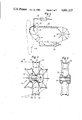
- FIG. 5 is a perspective view of a first version of a rerouting unit
- FIG. 6 is an elevation view in part cross-section of the U-shaped wire member of the rerouting unit of FIG. 5;
- FIG. 7 is a perspective view of another version of a rerouting unit
- FIG. 8 is a perspective view of still another version of a rerouting unit.
- FIG. 9 is a section along the line 9--9 of FIG. 8.
- the band-grinding machine shown schematically in FIGS. 1-4 consists substantially of a motor-driven contact disk 12 supported in a non-illustrated machine frame having a horizontal axle 10, a rerouting unit 14 axially parallel to the contact disk 12, and a grinding band 16 guided over the contact disk 12, and the rerouting unit 14; the grinding band is slack or non-resilient, when bent.
- An upper strand 18 of the grinding band 16 is guided over a sliding surface 20, which in turn is formed on the machine frame along an upper common tangential plane of the contact disk 12 and of the rerouting unit 14.
- the lower strand 24 of the grinding band is suspended downwardly either freely (FIG. 1), or is acted upon by a band-tensioning device 26 (FIGS. 2 and 3), or is subjected to suction (FIG. 4).
- the band-tensioning device 26 is implemented as a two-armed lever in the fashion of a scale, on whose loading arm there is disposed a pressure element 28 or 30 abutting the band, and which carries a displaceable weight 32 along the force-and/or loading-arm.
- the pressure element is implemented as a pressure shoe 28, while in the embodiment example according to FIG. 3 it is implemented as a rotatable rerouting unit 30, which has a low moment of inertia.
- the empty strand 24 of the downwardly hanging grinding band is guided through a box 34, which, in turn, is subjected to suction.
- a box 34 which, in turn, is subjected to suction.
- the contact disk 12 articulated on a belt crank or angle lever 36 may be pressed against a work 40 passing therealong, or be optionally guided therealong, while being subjected to a force adjustable to be constant under the influence of a slideable weight 38.
- the rerouting units 14 are provided along their periphery with cross-rod members 42, cross-rib members 44, or cross-edge members 46 spaced from another, which support the grinding band 16 guided thereover substantially in a line-like manner. So as to ensure use of a grinding band automatically laying its own track both at a low number of revolutions during the initial starting phase, as well as during high number of revolutions when in steady-state operation, even at low band tensions down to a band tension of zero, the cross-rod members 42, the cross-rib members 44, or the cross-edge members 46 are implemented so as to be concave facing the grinding band 16, and/or are provided with lateral track-guiding rims 48.
- the rerouting roller 30 of the band-tensioning device 26 can also be implemented in this manner.
- a rerouting unit 14 shown in FIGS. 5 and 6 there are fastened to its hub 50, implemented as a bearing, a plurality of U-shaped wire members 52, which extend radially outwardly, and are spaced from one another; their outwardly concavely curved cross-rod members 42 form a substantially line-shaped support for the grinding band 16.
- the radially outwardly curved rims 48 of the cross-rod members 42 additionally define a track for lateral guidance of the grinding band 16.
- the rerouting unit 14 has a very low moment of inertia in comparison to conventional rerouting rollers; it may therefore follow any changes in the peripheral velocity of the grinding band approximately instantaneously and without any slip, even at very low band tensions. In this manner it is possible to start up the grinding band 16 in a few seconds without any special arrangements and at a lowest band tension, even when the band is freely suspended from rest. Hence an operating velocity of the contact disk and of the rerouting unit of about 3,000 revolutions per second can be reached, and further the grinding band 16 can be stopped abruptly, even when it is travelling at its operating velocity, without the grinding band jumping off from the rerouting unit.
- the slight bend of the grinding band 16 within the region of the supporting cross-rod member 42 contributes significantly to that feature, which additionally leads to an increased adhesive friction between the grinding band and the contact roller. So as to increase adhesive friction even further, it is furthermore possible to provide within the region of the cross-rod members non-illustrated adhesive friction means, for example a rubber coating. In particular it is possible to surround the band trajectory of the rerouting units formed by the U-shaped wire members 52 with a non-illustrated expandable and tensionable rubber ring, so that there results an effective polygonal periphery of the band support, which hugs the passing grinding band at a high number of revolutions due to the action of the centrifugal force.
- the elastic bendability of the U-shaped wire members 52 which consist of resilient wire, contributes to the fact that any inertial forces which may occur when the machine is rapidly started or stopped, are transferred in a slip-free manner between the grinding band and the rerouting unit.
- the rerouting unit 14 can be supported on a rigid horizontal shaft of the machine frame. Due to the automatic guidance of the grinding band 16 on the rerouting unit 12, neither a displacement of the rerouting unit for the purpose of changing the axial spacing, nor a tilting thereof for the purpose of automatic matching to the trajectory of the band is required, as indeed has been the case in machines of the prior art.
- the band trajectory is conventionally convexly curved, as viewed at right angles to the longitudinal band direction, so as to prevent any jumping off of the grinding band 16 from the rerouting disk during operation of the machine. Due to the ensuing alternation between a convex curvature within the region of the contact disk 12, on one hand, and a concave curvature within the region of the rerouting unit 14, on the other hand, equalization of expansion takes place on the grinding band 16, which in turn results in a considerably longer life of the grinding band 16.
- the trajectory of the band is defined by plate-like punched or shaped members 62 projecting radially from a hub 60; the shaped members 62 are made of synthetic material or metal, whose radially outwardly projecting concave cross-edge members 46 extend at right angles to the longitudinal direction of the band, and so provide again a substantially line-shaped support for a grinding band 16 passing thereover.
- the rerouting unit 14 consists of a wire 64 bent into a circle, which, in turn, is connected through radially extending wires or spokes 66 to a hub 68; laterally extending wire ribs 44, which are concavely curved, are welded to, and project from the annularly shaped wire 64, thus providing a substantially line-shaped support.
- contact disks 12 which are formed with a soft contact surface, which expand radially due to the centrifugal force, and which therefore permit achievement of a particularly soft band grinding, is especially advantageous.
- the contact-forming surface of the contact disks is formed by laminae made, for example of textile material, which peripherally abut a rigid disk, and, while being normally slack, expand radially when the rigid disk is rapidly rotated due to the centrifugal force acting thereon; such laminae thus effectively increase the diameter of the disk under those circumstances, so as to form an extremely yieldable support for the grinding band. Consequently the grinding band, which is largely free of any tension, may now be still better matched, than has been the case hitherto, to any curvatures or channels formed in a surface of the workpiece.
Landscapes
- Engineering & Computer Science (AREA)
- Mechanical Engineering (AREA)
- Finish Polishing, Edge Sharpening, And Grinding By Specific Grinding Devices (AREA)
Abstract
A grinding machine equipped with a grinding band consists substantially of a motor-driven contact disk supported in a machine frame, which has a horizontal axle, a rotatable rerouting unit, which has a shaft parallel with the axle, and wherein the grinding band is slack and not bend-resisting, and is guided over the contact disk and the rerouting unit. In a take-up region of the contact disk there are disposed lateral guidance jaws of an abrasion-resistive ceramic material. A lower strand of the grinding band is suspended downwardly, while being acted upon by band-tensioning means. The rerouting unit includes a plurality of U-shaped wire members connected to a hub of the rerouting unit, spaced radially therefrom, and spaced from one another, whose outwardly concave cross-rods form a line-like support for the grinding band. As the U-shaped wire members are very lightweight, the rerouting unit has a very low moment of inertia, so that it can follow any changes in the rotating velocity of the grinding band almost instantaneously, and in a slip-free manner, even at the lowest band tension.
Description
1. German Pat. No. DE 2400267.
2. Concurrently filed application "Polishing Disk".
The present invention relates to a machine equipped with a grinding band, which includes a frame, a contact disk supported in the frame and optionally driven by a 10 motor, at least one rotatable rerouting unit having an axle parallel to that of the contact disk, and a grinding band guided over the contact disk and the rerouting unit.
In a band-grinding machine of this type, which includes a motor-operable contact disk, it is known from German Pat. No. DE 2400267 to make use of a rerouting roller, which has a relatively low mass compared to its diameter, and to provide a band-tensioning device, which at the operating velocity of the grinding band, subjects the grinding band to a low force of about 0.5 to 5N. The rerouting roller is formed thereat as a spoke wheel, the periphery of which is formed as a smooth circular running surface. So as to avoid any jumping off of the grinding band at high velocities of travel, the running surface of the rerouting roller, as well as that of the contact disk is outwardly convexly curved in a direction at right angles to the longitudinal direction of the band. But in order to prevent the grinding band from jumping off also during starting, the grinding band is initially adjusted to an increased tension with the aid of a band tensioning device and/or by means of an adjustment of the axial spacing between the rerouting roller and the contact disk. After the required band velocity has been reached, which is suitable for grinding, the band tension is reduced thereafter to a somewhat lower value suitable for normal operation. When the band is gradually or abruptly brought to a halt, it is hard, however, to avoid any further rotation of the rerouting roller, in spite of its low weight, and to prevent the grinding band from coming off therefrom.
It is an object of the invention to create a band grinding machine of the initially described type, which ensures a largely slip-free entrainment of the rerouting unit, even at very low band tensions, and both at low band velocities, as well as at high band velocities, and when the band velocity is abruptly changed.
This object of the invention is attained by the rerouting unit including along its peripheral direction crossrod-members, rib-members or edge-members spaced from one another, and forming a band support, which in turn substantially provides a line-shaped support for the grinding band covering these members; thus the grinding band forms a polygon, as seen in side view.
The invention is based on the recognition that a rerouting unit is better entrained by a grinding band at low tension, and which does not resist bending, if its band support or running surface is not round, but is formed with crossrods, which in turn may be surrounded by the band, so that the band has a polygonal periphery. Due to the formation of a slight bend in the grinding band within the region of the crossrods, an increased adhesive resistance between the grinding band and the contact disk results. If, in a preferred embodiment of the invention, the band support of the rerouting unit is formed by substantially U-shaped wire units, where the wire units are peripherally spaced from one another, and extend radially from a hub of the rerouting unit, and where each U-shaped wire unit includes a crossbar, then the construction of the rerouting unit is particularly lightweight, and has the lowest possible moment of inertia. Such a rerouting unit may follow almost instantaneously and without any slip any changes in the velocity of rotation of the grinding band, even at the lowest band tension.
If the support bars, support ribs or support edges of the rerouting unit are considerably wider than the width of the grinding band, then a grinding band guided in a take-up region of the contact disk automatically aligns itself on the rerouting unit. But it has been shown to be particularly advantageous to provide a separate lateral guidance on the rerouting unit, which may be formed by the support bars, support ribs or support edges being concavely curved facing the grinding band and/or having at the ends radially extending rims forming a track for the band. Such guiding means are effective both at low peripheral band velocities, as well as at high band peripheral velocities, down to the lowest possible band tensions, and even permit operation with a freely suspended grinding band.
The novel features which are considered as characteristic of the invention are set forth in particular in the appended claims. The invention itself, however, both as to its construction and method of operation, together with additional objects and advantages thereof, will best be understood from the following description of the specific embodiments read in connection with the accompanying drawings.
FIG. 1 is a side view of a band-grinding machine having a star-shaped rerouting unit, and a freely suspended grinding band;
FIG. 2 is a side view of a band-grinding machine equipped with a band-tensioning arrangement;
FIG. 3 is a side view of a further embodiment example of a band-grinding machine having a band-tensioning arrangement;
FIG. 4 is a side view of an automatic band-grinding machine equipped with a suction box;
FIG. 5 is a perspective view of a first version of a rerouting unit;
FIG. 6 is an elevation view in part cross-section of the U-shaped wire member of the rerouting unit of FIG. 5;
FIG. 7 is a perspective view of another version of a rerouting unit;
FIG. 8 is a perspective view of still another version of a rerouting unit; and
FIG. 9 is a section along the line 9--9 of FIG. 8.
The band-grinding machine shown schematically in FIGS. 1-4 consists substantially of a motor-driven contact disk 12 supported in a non-illustrated machine frame having a horizontal axle 10, a rerouting unit 14 axially parallel to the contact disk 12, and a grinding band 16 guided over the contact disk 12, and the rerouting unit 14; the grinding band is slack or non-resilient, when bent. An upper strand 18 of the grinding band 16 is guided over a sliding surface 20, which in turn is formed on the machine frame along an upper common tangential plane of the contact disk 12 and of the rerouting unit 14. In the take-up region of the contact disk 12, there may be disposed lateral guidance jaws made of a ceramic material, which resists grinding (FIGS. 2-4). The lower strand 24 of the grinding band is suspended downwardly either freely (FIG. 1), or is acted upon by a band-tensioning device 26 (FIGS. 2 and 3), or is subjected to suction (FIG. 4).
The band-tensioning device 26, according to FIGS. 2 and 3, is implemented as a two-armed lever in the fashion of a scale, on whose loading arm there is disposed a pressure element 28 or 30 abutting the band, and which carries a displaceable weight 32 along the force-and/or loading-arm. In the embodiment example according to FIG. 2, the pressure element is implemented as a pressure shoe 28, while in the embodiment example according to FIG. 3 it is implemented as a rotatable rerouting unit 30, which has a low moment of inertia.
In the version shown in FIG. 4, the empty strand 24 of the downwardly hanging grinding band is guided through a box 34, which, in turn, is subjected to suction. Here it is shown schematically how the contact disk 12 articulated on a belt crank or angle lever 36, may be pressed against a work 40 passing therealong, or be optionally guided therealong, while being subjected to a force adjustable to be constant under the influence of a slideable weight 38.
The rerouting units 14 are provided along their periphery with cross-rod members 42, cross-rib members 44, or cross-edge members 46 spaced from another, which support the grinding band 16 guided thereover substantially in a line-like manner. So as to ensure use of a grinding band automatically laying its own track both at a low number of revolutions during the initial starting phase, as well as during high number of revolutions when in steady-state operation, even at low band tensions down to a band tension of zero, the cross-rod members 42, the cross-rib members 44, or the cross-edge members 46 are implemented so as to be concave facing the grinding band 16, and/or are provided with lateral track-guiding rims 48. The rerouting roller 30 of the band-tensioning device 26 can also be implemented in this manner.
In the implementation example of a rerouting unit 14 shown in FIGS. 5 and 6, there are fastened to its hub 50, implemented as a bearing, a plurality of U-shaped wire members 52, which extend radially outwardly, and are spaced from one another; their outwardly concavely curved cross-rod members 42 form a substantially line-shaped support for the grinding band 16. The radially outwardly curved rims 48 of the cross-rod members 42 additionally define a track for lateral guidance of the grinding band 16. As the U-shaped wire members 52 are very lightweight, the rerouting unit 14 has a very low moment of inertia in comparison to conventional rerouting rollers; it may therefore follow any changes in the peripheral velocity of the grinding band approximately instantaneously and without any slip, even at very low band tensions. In this manner it is possible to start up the grinding band 16 in a few seconds without any special arrangements and at a lowest band tension, even when the band is freely suspended from rest. Hence an operating velocity of the contact disk and of the rerouting unit of about 3,000 revolutions per second can be reached, and further the grinding band 16 can be stopped abruptly, even when it is travelling at its operating velocity, without the grinding band jumping off from the rerouting unit. The slight bend of the grinding band 16 within the region of the supporting cross-rod member 42 contributes significantly to that feature, which additionally leads to an increased adhesive friction between the grinding band and the contact roller. So as to increase adhesive friction even further, it is furthermore possible to provide within the region of the cross-rod members non-illustrated adhesive friction means, for example a rubber coating. In particular it is possible to surround the band trajectory of the rerouting units formed by the U-shaped wire members 52 with a non-illustrated expandable and tensionable rubber ring, so that there results an effective polygonal periphery of the band support, which hugs the passing grinding band at a high number of revolutions due to the action of the centrifugal force.
Furthermore, the elastic bendability of the U-shaped wire members 52, which consist of resilient wire, contributes to the fact that any inertial forces which may occur when the machine is rapidly started or stopped, are transferred in a slip-free manner between the grinding band and the rerouting unit.
It is no longer required to readjust the band tension during starting and stopping. Furthermore the rerouting unit 14 can be supported on a rigid horizontal shaft of the machine frame. Due to the automatic guidance of the grinding band 16 on the rerouting unit 12, neither a displacement of the rerouting unit for the purpose of changing the axial spacing, nor a tilting thereof for the purpose of automatic matching to the trajectory of the band is required, as indeed has been the case in machines of the prior art.
At bends of the band in the region of the line-shaped band support any gaps between the grinding particles are expanded, so that during operation and at a high number of revolutions the band is automatically cleared or emptied of any dust particles embedded therein due to the centrifugal force acting thereon. This applies to the entire grinding band surface, as during operation each location of the grinding band reaches the line-shaped supports of the rerouting unit 14 sufficiently frequently. The rerouting unit can therefore also be used as an ejector.
Within the region of the contact disk 12 the band trajectory is conventionally convexly curved, as viewed at right angles to the longitudinal band direction, so as to prevent any jumping off of the grinding band 16 from the rerouting disk during operation of the machine. Due to the ensuing alternation between a convex curvature within the region of the contact disk 12, on one hand, and a concave curvature within the region of the rerouting unit 14, on the other hand, equalization of expansion takes place on the grinding band 16, which in turn results in a considerably longer life of the grinding band 16.
In the version of the rerouting unit shown in FIG. 7, the trajectory of the band is defined by plate-like punched or shaped members 62 projecting radially from a hub 60; the shaped members 62 are made of synthetic material or metal, whose radially outwardly projecting concave cross-edge members 46 extend at right angles to the longitudinal direction of the band, and so provide again a substantially line-shaped support for a grinding band 16 passing thereover.
In the embodiment example according to FIGS. 8 and 9 the rerouting unit 14 consists of a wire 64 bent into a circle, which, in turn, is connected through radially extending wires or spokes 66 to a hub 68; laterally extending wire ribs 44, which are concavely curved, are welded to, and project from the annularly shaped wire 64, thus providing a substantially line-shaped support.
In connection with the aforedescribed rerouting units 14, use of contact disks 12, which are formed with a soft contact surface, which expand radially due to the centrifugal force, and which therefore permit achievement of a particularly soft band grinding, is especially advantageous. In particular, for the first time operation of contact disks is possible, which does not require any adjustment of the tension of the band; namely the contact-forming surface of the contact disks is formed by laminae made, for example of textile material, which peripherally abut a rigid disk, and, while being normally slack, expand radially when the rigid disk is rapidly rotated due to the centrifugal force acting thereon; such laminae thus effectively increase the diameter of the disk under those circumstances, so as to form an extremely yieldable support for the grinding band. Consequently the grinding band, which is largely free of any tension, may now be still better matched, than has been the case hitherto, to any curvatures or channels formed in a surface of the workpiece.
While the invention has been illustrated in preferred embodiments, it is not to be limited to the structures shown, since many variations thereof will be evident to one skilled in the art, and are intended to be encompassed in the present invention as set forth in the following claims.
Claims (22)
1. In a grinding machine using a longitudinal grinding band, and including a frame, a driven contact disk having an axle, and supported in the frame on said axle, a rotatable rerouting unit having a shaft disposed approximately parallel with said axle, said grinding band being guided over said contact disk and over said rerouting unit,
the improvement in said rerouting unit comprising
a plurality of members peripherally spaced from one another and extending transverse to the longitudinal direction so as to form substantially line-shaped supports for said grinding band, each member having a concavely formed side facing said grinding band, whereby the grinding band operatively assumes a substantially polygonal shape as seen in a sideview thereof.
2. The grinding machine as set forth in claim 1, wherein each member is a cross-bar.
3. The grinding machine as set forth in claim 1, wherein each member is a cross-rib.
4. The grinding machine as set forth in claim 1, wherein each member is a cross-edge member.
5. The grinding machine as set forth in claim 1, wherein each member has a concavely curved side facing said grinding band.
6. The grinding machine as set forth in claim 1, wherein each member has radially outwardly projecting lateral rim portions guiding said grinding band therebetween.
7. The grinding machine as set forth in claim 1, wherein said members form a peripheral support surface for said grinding band, wherein said rerouting unit includes a hub, and wherein each member is a U-shaped wire member extending radially from said hub.
8. The grinding machine as set forth in claim 1, wherein said members form a peripheral support surface for said grinding band, wherein said rerouting unit includes a hub, and wherein each member is a plate-shaped member.
9. The grinding machine as set forth in claim 8, wherein each member is made of synthetic material.
10. The grinding machine as set forth in claim 8, wherein each member is punched from metal.
11. The grinding machine as set forth in claim 1, wherein said members form a peripheral support surface for said grinding band, and wherein at least a support-forming part of each member is made of resilient material.
12. The grinding machine as set forth in claim 1, wherein said members form a peripheral support surface for said grinding band, and wherein at least a support-forming part of each member is made of bendable material.
13. The grinding machine as set forth in claim 1, wherein said members form a peripheral support surface for said grinding band, and wherein at least a support-forming part of each member includes adhesive means.
14. The grinding machine as set forth in claim 13, wherein said adhesive means includes rubber.
15. The grinding machine as set forth in claim 1, wherein said members form a peripheral support surface for said grinding band, and further comprising a rubber ring under tension extending over said support surface.
16. The grinding machine as set forth in claim 1, wherein said members form a peripheral support surface for said grinding band, said peripheral support surface having a predetermined diameter, and wherein said rerouting unit has a very low moment of inertia in relation to said diameter.
17. The grinding machine as set forth in claim 1, wherein said grinding band includes upper and lower strands, and further comprising a slide surface disposed within a region of said upper strand in a plane about tangent both with said contact disk and with said rerouting unit, said upper strand band being guided along said slide surface, while said lower strand is freely suspended downwardly from said contact disk and from said rerouting unit.
18. The grinding machine as set forth in claim 1, wherein said grinding band includes upper and lower strands, and further comprising a slide surface disposed within a region of said upper strand in a plane about tangent both with said contact disk and with said rerouting unit, and band-tensioning means exerting an adjustable pressure on said grinding band, said upper strand band being guided along said slide surface, said lower strand being suspended downwardly while being acted on by said band-tensioning means.
19. The grinding machine as set forth in claim 18, further comprising a second rotatable rerouting unit abutting an inner side of said grinding band, said second rerouting unit including a set of members spaced from one another and extending in a direction transverse to the longitudinal direction of the grinding band, each of said set of members substantially abutting said grinding band in a line-like manner.
20. The grinding machine as set forth in claim 1, wherein said grinding band includes a lower strand, and further including under-pressure generating means, said lower strand being passed through said under-pressure generating means so that the under-pressure thereof pulls said grinding band slightly downwardly.
21. In a grinding machine using a longitudinal grinding band, and including a frame, a driven contact disk having an axle, and supported in the frame on said axle, a rotatable rerouting unit having a shaft disposed approximately parallel with said axle, said grinding band being guided over said contact disk and over said rerouting unit,
the improvement in said rerouting unit comprising
a plurality of members peripherally spaced from one another and extending transverse to the longitudinal direction so as to form substantially line-shaped supports for said grinding band, each member having radially outwardly projecting lateral rim portions guiding said grinding band therebetween, whereby the grinding band operatively assumes a substantially polygonal shape as seen in a sideview thereof.
22. The grinding machine as set forth in claim 1, wherein said grinding band is made of material which does not resist bending, and wherein said rerouting unit is operatively entrained by said grinding band at low tension.
Applications Claiming Priority (1)
| Application Number | Priority Date | Filing Date | Title |
|---|---|---|---|
| DE19833335758 DE3335758A1 (en) | 1983-10-01 | 1983-10-01 | BELT GRINDING MACHINE |
Publications (1)
| Publication Number | Publication Date |
|---|---|
| US4601132A true US4601132A (en) | 1986-07-22 |
Family
ID=6210728
Family Applications (1)
| Application Number | Title | Priority Date | Filing Date |
|---|---|---|---|
| US06/689,065 Expired - Fee Related US4601132A (en) | 1983-10-01 | 1985-01-07 | Machine equipped with a grinding band |
Country Status (3)
| Country | Link |
|---|---|
| US (1) | US4601132A (en) |
| EP (1) | EP0179167A1 (en) |
| DE (1) | DE3335758A1 (en) |
Cited By (1)
| Publication number | Priority date | Publication date | Assignee | Title |
|---|---|---|---|---|
| US4717027A (en) * | 1986-03-28 | 1988-01-05 | Laros Equipment Company, Inc. | Vibratory belt separator for blow-molded parts |
Families Citing this family (1)
| Publication number | Priority date | Publication date | Assignee | Title |
|---|---|---|---|---|
| CN111113214A (en) * | 2019-12-31 | 2020-05-08 | 金肯职业技术学院 | Artwork polishing device and polishing method thereof |
Citations (11)
| Publication number | Priority date | Publication date | Assignee | Title |
|---|---|---|---|---|
| US272433A (en) * | 1883-02-20 | Reel for chain-pumps | ||
| US2479506A (en) * | 1948-01-02 | 1949-08-16 | Payton Andy Leslie | Molding sander |
| US2497949A (en) * | 1949-06-29 | 1950-02-21 | Howard T Linsmeier | Egg cleaning machine |
| US2556041A (en) * | 1949-10-25 | 1951-06-05 | Lewis G Pick | Tool for preparing pipes and fittings for soldered, brazed, or coupling assembly |
| US2725691A (en) * | 1953-02-12 | 1955-12-06 | Sommer & Maca Glass Machinery | Platen and support for abrading apparatus |
| US2732669A (en) * | 1956-01-31 | Apparatus and method of oil polishing | ||
| US2763103A (en) * | 1954-03-12 | 1956-09-18 | Bader Stephen | Belt grinding and polishing machine |
| US3400804A (en) * | 1967-04-05 | 1968-09-10 | Charles E. Phillips | Continuous belt conveyor for unloading granular material from hoppers |
| US3488889A (en) * | 1968-01-23 | 1970-01-13 | John Stanley Mccay | Portable combination flattened cylindrical sander-grinder |
| US3507160A (en) * | 1968-08-08 | 1970-04-21 | United States Steel Corp | Self-centering roll |
| US4185609A (en) * | 1978-06-23 | 1980-01-29 | Frank Petera | Band type lapidary saw |
Family Cites Families (10)
| Publication number | Priority date | Publication date | Assignee | Title |
|---|---|---|---|---|
| US759995A (en) * | 1903-05-07 | 1904-05-17 | Donald Valentine Hodd | Sandpapering-machine. |
| DE452302C (en) * | 1925-11-07 | 1927-11-08 | Mueller Paul | Composed revolving body of circular, polygonal or other cross-section for roller table rollers, pulleys, drums, wheels and the like. like |
| US2494676A (en) * | 1945-11-26 | 1950-01-17 | Schuur John K Van Der | Clamp guide |
| FR1076317A (en) * | 1953-03-10 | 1954-10-26 | Tecalemit | Mechanism controlled by the difference in rotational speed of two shafts and its application to anti-slip devices |
| US3038590A (en) * | 1961-02-27 | 1962-06-12 | Goodman Mfg Co | Fluted tail pulley |
| US3226884A (en) * | 1963-09-06 | 1966-01-04 | Casimer J Mellerski | Abrading machine |
| US3392594A (en) * | 1966-04-15 | 1968-07-16 | Franklin Van Gorp | Rubber lagged wing pulley |
| US3995487A (en) * | 1975-09-08 | 1976-12-07 | Reliance Electric Company | Self cleaning pulley for conveyor belts |
| GB1490172A (en) * | 1975-12-03 | 1977-10-26 | Inst Mekhaniki Metallopolimern | Pressure roller |
| AT354288B (en) * | 1978-03-08 | 1979-12-27 | Langzauner & Soehne Joh | BELT SANDING MACHINE |
-
1983
- 1983-10-01 DE DE19833335758 patent/DE3335758A1/en not_active Withdrawn
-
1984
- 1984-10-26 EP EP84112934A patent/EP0179167A1/en not_active Withdrawn
-
1985
- 1985-01-07 US US06/689,065 patent/US4601132A/en not_active Expired - Fee Related
Patent Citations (11)
| Publication number | Priority date | Publication date | Assignee | Title |
|---|---|---|---|---|
| US272433A (en) * | 1883-02-20 | Reel for chain-pumps | ||
| US2732669A (en) * | 1956-01-31 | Apparatus and method of oil polishing | ||
| US2479506A (en) * | 1948-01-02 | 1949-08-16 | Payton Andy Leslie | Molding sander |
| US2497949A (en) * | 1949-06-29 | 1950-02-21 | Howard T Linsmeier | Egg cleaning machine |
| US2556041A (en) * | 1949-10-25 | 1951-06-05 | Lewis G Pick | Tool for preparing pipes and fittings for soldered, brazed, or coupling assembly |
| US2725691A (en) * | 1953-02-12 | 1955-12-06 | Sommer & Maca Glass Machinery | Platen and support for abrading apparatus |
| US2763103A (en) * | 1954-03-12 | 1956-09-18 | Bader Stephen | Belt grinding and polishing machine |
| US3400804A (en) * | 1967-04-05 | 1968-09-10 | Charles E. Phillips | Continuous belt conveyor for unloading granular material from hoppers |
| US3488889A (en) * | 1968-01-23 | 1970-01-13 | John Stanley Mccay | Portable combination flattened cylindrical sander-grinder |
| US3507160A (en) * | 1968-08-08 | 1970-04-21 | United States Steel Corp | Self-centering roll |
| US4185609A (en) * | 1978-06-23 | 1980-01-29 | Frank Petera | Band type lapidary saw |
Cited By (1)
| Publication number | Priority date | Publication date | Assignee | Title |
|---|---|---|---|---|
| US4717027A (en) * | 1986-03-28 | 1988-01-05 | Laros Equipment Company, Inc. | Vibratory belt separator for blow-molded parts |
Also Published As
| Publication number | Publication date |
|---|---|
| EP0179167A1 (en) | 1986-04-30 |
| DE3335758A1 (en) | 1985-04-18 |
Similar Documents
| Publication | Publication Date | Title |
|---|---|---|
| JP2799283B2 (en) | Rewinding machine and method for producing logs of web material without winding core and logs without core or central winding tube and without central hole | |
| US4669677A (en) | Yarn storage and delivery arrangement, particularly for textile machines | |
| ES2081518T3 (en) | MANUFACTURING PROCEDURE OF A TIRE, AND APPARATUS FOR THE PERFORMANCE OF SUCH PROCEDURE. | |
| US4601132A (en) | Machine equipped with a grinding band | |
| NL192094C (en) | Device for connecting a band-reinforced band-like material to a band. | |
| US4257301A (en) | Circular saw blade | |
| JPH0542796A (en) | Processing device for strip-like material | |
| JPH04201066A (en) | Preventing device for bias of endless belt and belt working device using same device | |
| US3098324A (en) | Polishing method and means | |
| US5007208A (en) | Anchor for rotary sanding drum | |
| JPS60215853A (en) | Yarn positive feeder in fiber machine | |
| JP4018918B2 (en) | Shot apparatus and shot method | |
| US2824319A (en) | Polishing machine for polishing the coupling links of separable slide fasteners | |
| JPS6236830B2 (en) | ||
| JP5918068B2 (en) | Belt mounting jig | |
| US3039713A (en) | Punch mechanism for perforating film | |
| US1156958A (en) | Ring-polishing machine. | |
| US3005370A (en) | Film perforating apparatus | |
| RU2134171C1 (en) | Flexible cable unwinding device | |
| KR19990012339U (en) | Needle Polishing Device | |
| JP3464939B2 (en) | Power transmission belt and method of manufacturing the same | |
| EP0273477B1 (en) | Yarn tensioning device in the form of rotary discs | |
| JPS5912442B2 (en) | Curl straightening machine for veneer veneer with automatic adjustment device | |
| JPS627641Y2 (en) | ||
| US2492849A (en) | Sander drum and floor sanding abrasive sheet |
Legal Events
| Date | Code | Title | Description |
|---|---|---|---|
| REMI | Maintenance fee reminder mailed | ||
| LAPS | Lapse for failure to pay maintenance fees | ||
| STCH | Information on status: patent discontinuation |
Free format text: PATENT EXPIRED DUE TO NONPAYMENT OF MAINTENANCE FEES UNDER 37 CFR 1.362 |
|
| FP | Lapsed due to failure to pay maintenance fee |
Effective date: 19900722 |