US4558473A - Sanitary cleaning equipment - Google Patents
Sanitary cleaning equipment Download PDFInfo
- Publication number
- US4558473A US4558473A US06/557,165 US55716583A US4558473A US 4558473 A US4558473 A US 4558473A US 55716583 A US55716583 A US 55716583A US 4558473 A US4558473 A US 4558473A
- Authority
- US
- United States
- Prior art keywords
- wind tunnel
- opening
- fan
- damper
- fan chamber
- Prior art date
- Legal status (The legal status is an assumption and is not a legal conclusion. Google has not performed a legal analysis and makes no representation as to the accuracy of the status listed.)
- Expired - Fee Related
Links
Images


Classifications
-
- E—FIXED CONSTRUCTIONS
- E03—WATER SUPPLY; SEWERAGE
- E03D—WATER-CLOSETS OR URINALS WITH FLUSHING DEVICES; FLUSHING VALVES THEREFOR
- E03D9/00—Sanitary or other accessories for lavatories ; Devices for cleaning or disinfecting the toilet room or the toilet bowl; Devices for eliminating smells
- E03D9/08—Devices in the bowl producing upwardly-directed sprays; Modifications of the bowl for use with such devices ; Bidets; Combinations of bowls with urinals or bidets; Hot-air or other devices mounted in or on the bowl, urinal or bidet for cleaning or disinfecting
-
- E—FIXED CONSTRUCTIONS
- E03—WATER SUPPLY; SEWERAGE
- E03D—WATER-CLOSETS OR URINALS WITH FLUSHING DEVICES; FLUSHING VALVES THEREFOR
- E03D9/00—Sanitary or other accessories for lavatories ; Devices for cleaning or disinfecting the toilet room or the toilet bowl; Devices for eliminating smells
- E03D9/04—Special arrangement or operation of ventilating devices
- E03D9/05—Special arrangement or operation of ventilating devices ventilating the bowl
- E03D9/052—Special arrangement or operation of ventilating devices ventilating the bowl using incorporated fans
-
- Y—GENERAL TAGGING OF NEW TECHNOLOGICAL DEVELOPMENTS; GENERAL TAGGING OF CROSS-SECTIONAL TECHNOLOGIES SPANNING OVER SEVERAL SECTIONS OF THE IPC; TECHNICAL SUBJECTS COVERED BY FORMER USPC CROSS-REFERENCE ART COLLECTIONS [XRACs] AND DIGESTS
- Y10—TECHNICAL SUBJECTS COVERED BY FORMER USPC
- Y10S—TECHNICAL SUBJECTS COVERED BY FORMER USPC CROSS-REFERENCE ART COLLECTIONS [XRACs] AND DIGESTS
- Y10S4/00—Baths, closets, sinks, and spittoons
- Y10S4/06—Heated seats
Definitions
- This invention relates to a sanitary cleaning equipment comprising a flushing device adapted to deliver a jet of cleaning water to a selected area to be cleaned, a deodorizing device for withdrawing odoriferous air from the neighborhood of said selected area, and a dryer adapted to deliver a jet of warm air to said area.
- a sanitary cleaning equipment of this type is generally used in combination with a western-style water closet.
- This equipment consists of a flushing device for cleaning a selected area of the user's body with a jet of cleaning water from a nozzle 4 disposed within a toilet (1), a dryer unit 9 for directing a jet of warm air against said area to thereby dry the same, and a deodorizing unit 11 for withdrawing odoriferous air from the neighborhood of said part within the toilet and deodorizing the air by passage thereof through a deodorant.
- said sanitary cleaning equipment comprises a pump 6 for drawing up water from a tank 5 disposed in the water closet and supplying it under pressure to said nozzle 4, and a warm water tank 7 interposed between said pump 6 and said nozzle 4 and equipped with the heater for warming a cleaning water.
- Said dryer unit 9 comprises a motor 8, a fan and a heater (not shown) for generating a warm air current for drying the flushed area of the user's body.
- Said deodorizing unit 11 comprises a deodorant tank 10, and control sections 12 and 13.
- a heater 3 is embedded in a cover 2 on the bowl 1.
- a heater for generating a warm air current and a deodorant having a relatively large flow resistance must be provided in the same air passageway and this imposes a new problem.
- the deodorant is present in the current passageway even when the warm drying air current is made available, the deodorant being unnecessary in this case, and since the deodorant acts as a large resistance to the air current, the current cannot have a sufficiently high velocity so that the warm air blowing efficiency is lowered.
- a motor having an increased capacity has to be provided.
- this invention was conceived to provide air currents for both the drying and deodorizing functions through use of a single fan means to thereby reduce the size of the whole equipment and prevent a decrease of the warm air blowing efficiency.
- this invention provides a system such that a first wind tunnel having a deodorant disposed therein and a second wind tunnel having a heater unit disposed therein are selectively communicated with a single fan unit.
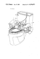
- FIG. 1 is a perspective exterior view showing a sanitary cleaning equipment embodying the principles of this invention
- FIG. 2 is a perspective view showing the construction of the main elements of the same equipment
- FIG. 3 is a cross-sectional view showing the constructions of the deodorizing and drying sections of the same equipment
- FIG. 4 is a perspective view showing the wind tunnel section of the same equipment
- FIGS. 5, 6, 7 and 8 are explanatory diagrams showing the relation of said wind tunnel section with related parts
- FIG. 9a, b are a perspective view of the damper adapted to effect a switching of the wind tunnels of the same equipment and a cross-sectional view of the shaft portion thereof;
- FIG. 10 is a perspective view showing the conventional sanitary cleaning equipment.
- FIG. 1 there is shown a toilet bowl 14 fitted with a seat 15 having an air heater embedded therein (not shown), with a cover 16 being additionally disposed to open and close the bowl. Further, disposed behind said toilet bowl 14 is a sanitary cleaning equipment body 17.
- the above-mentioned sanitary cleaning equipment body 17 has the construction illustrated in FIG. 2. It should be understood that an outer cover therefor is omitted from the illustration.
- a wind tunnel unit 25 Disposed on the other side of the top of said base member 18 is a wind tunnel unit 25.
- a motor 26 and a fan 27 which are best seen in FIG. 3, a drying/deodorizing switching control means 28, a source control means 29 therefor, and a control means 30 for adjusting the flow velocity of cleaning water.
- a timer 31, disposed atop, is intended to ensure that even after the user has left the toilet seat 15 after using the toilet and the starter switch 24 has consequently been switched off, the above-mentioned motor 26 will keep running for a preset time period.
- the wind tunnel unit 25 has a fan chamber 32 at one end thereof, a first wind tunnel 33 and a second wind tunnel 34. Openings 35, 36 of said first and second wind tunnels 33, 34 at one end thereof are disposed in common plane relationship and communicate with said fan chamber 32, while the other respective ends 37, 38 are disposed near the central edge of said base member 18 and directed toward the bowl 1.
- a face plate (a top plate in this embodiment) of said fan chamber 32 which is perpendicular to the openings 35, 36 of said first and second wind tunnels 33, 34 is provided with openings 39, 40 which are substantially equal in size to the corresponding openings 35, 36 on extension lines of said openings 35, 36 (FIG. 4).
- Disposed in said fan chamber 32 are a motor 26 and a silocco fan 27 directly coupled to said motor 26.
- a damper 41 is disposed across the openings 35, 36 of said first and second wind tunnels 33, 34. As shown in FIG. 9, this damper 41 consists of a shaft 42 and a first damper plate 43 and a second damper plate 44 both extending along the shaft.
- the damper plate 43 and the damper plate 44 project from the shaft 42 in perpendicular directions. Moreover, the first damper plate 43 is configured to project on one side of said shaft 42, while said second damper plate 44 actually consists of a couple of plate members 44a, 44b projecting on both sides of the shaft 42.
- the first damper plate 43 and the plate members 44a, 44b of the second damper plate 44 are configured to close up the openings 35, 36 of the first and second wind tunnels 33, 34 and the openings 39, 40 of the fan chamber 32, respectively.
- Projecting from one end of the plate member 44b of the second damper plate 44 is an actuating member 45 for actuating a switch which is described hereinafter. As shown in FIGS.
- the above-mentioned damper 41 is pivotally mounted with its shaft 42 extending on the common line of the openings 39, 40 of the fan chamber 32 and the openings 35, 36 of the wind tunnels 33, 34. Therefore, the first damper plates 43 is adapted to open and close the opening 35 of the first wind tunnel 33 and the first opening 39 of the fan chamber 32, while the first plate member 44a of the second damper plate 44 is adapted to open and close the opening 36 of the second wind tunnel 34 and the second plate member 44b is adapted to open and close the second opening 40 of the fan chamber 32. Furthermore, when the above-mentioned second plate member 44b closes the second opening 40 of the fan chamber 32, the actuating member 45 projecting from the end thereof depresses the drying heater switch 46 disposed at an edge of said opening 40 to turn it on.
- one end of the shaft 42 of said damper 41 is connected to a control knob 50 through connecting members 47, 48, 49 and it is so constructed that the damper 41 can be switched from one position to the other by turning this control knob 50.
- one end of said shaft 42 is formed as an angular shaft portion 51 which is sandwiched between a pair of resilient plates 53, 54 which are secured in position at both ends thereof by retaining means 52.
- the shaft 42 is rotated in a stepwise motion through 90 degrees and is stably maintained in either of the angular positions.
- the above-mentioned angular shaft portion 51 is not exactly square in cross-section but is deformed in a diamond-like quadrangular shape having acute and obtuse angles. Therefore, when this member is pressure-supported between the parallel resilient plates 53, 54, it is biased to turn in one direction as indicated by the arrow-mark (A) (the counterclockwise direction on the drawing). Therefore, the actuating member 45 of the plate member 44b exerts a strong pressing force on the switch 46, while the damper plates 43, 44 are pressed against the edges of the openings to be closed.
- a deodorant mounting hole 55 is formed in the above-mentioned first wind tunnel 33 and a deodorant cartridge 56 (see FIGS. 3 and 6) packed with a deodorant such as activated carbon is inserted from said deodorant mounting hole 55.
- a heater 57 is built in the second wind tunnel 34 for generating a warm air blast. Therefore, the first wind tunnel 33 serves as a wind tunnel for deodorization while the second wind tunnel 34 is adapted to function as a drying wind tunnel.
- the wind tunnel structure 25 is formed as a unit from a synthetic resin such as polypropylene.
- the start switch 24 is switched on, by the load so applied, to energize the motor 26, which, in turn, drives the fan 27.
- the heater in the toilet seat 15 has already been energized to heat the seat.
- the drying/deodorization control section 28 set on the deodorization side, the deodorization mode is executed as will hereinafter be described in detail.
- the user after having used the toilet, manipulates the pump 19, warm cleaning water emerges in jets from the nozzle 22 and washes the selected area of the user's body.
- the drying/deodorization control section 28 is switched to the other side, whereupon a warm blast of air is supplied from the opening 38 into the toilet bowl 14 to dry the selected body area. Thereafter, the drying/deodorization control section 28 is switched back to the deodorization side. As the user leaves the toilet seat 15, the start switch is switched off but the deodorization mode is further executed for a time determined by the timer 31, at the end of which time the power source therefor is switched off.
- the above embodiment is such that the air blast for deodorization and drying is effected by a single fan means comprising a motor 26 and a fan, and is characterized by its wind tunnel construction and switching means.
- a fan chamber 32 is disposed at one end of a wind tunnel means 25, and a first wind tunnel 33 having a deodorant means such as a deodorant cartridge 56 and a second wind tunnel having a heater 57 have their respective openings 35 and 36 in a common plane adjacent to said fan chamber 32.
- the fan chamber 32 has openings 39 and 40 corresponding to said openings 35 and 36, respectively, and each is adapted to be closed and opened in response to the rotation of the damper 41 so that said first wind tunnel 33 and second wind tunnel 34 are selectively brought into communication with the fan chamber 32 of a single fan means, whereby either the deodorization mode or the drying mode is selectively executed.
- the first damper plate 43 opens the opening 35 of said first wind tunnel 33 and closes the corresponding first opening 39 of the fan chamber 32.
- the plate member 44a closes the opening of said second wind tunnel 34, while the corresponding opening 40 of said fan chamber 32 is not closed by its plate member 44b.
- the actuating member 45 of said plate member 44b is located apart from the switch 46, the heater 5 in the second wind tunnel 34 is not energized so that the heater 57 does not generate heat. Therefore, in the state shown in FIG.
- the damper 41 is turned through about 90 degrees.
- the first damper plate 43 closes the opening 35 of said first wind tunnel 33 and the plate member 44a of the second damper plate 44 opens the opening 36 of said second wind tunnel 34, with the plate member 44b closing the opening 40 of the fan chamber 32.
- the actuating member 45 presses the switch 46 ON to energize the heater 57 in said second wind tunnel 34 to generate heat. Therefore, only the second wind tunnel 34 is associated with the fan 27, with the first wind tunnel 33 being not functioning at all. Due to the rotation of the fan 27, the atmospheric air is introduced from the opening 39 of the fan chamber 32 and supplied under pressure to the second wind tunnel 33, where it is warmed by the heater 57.
- the resultant warm air flow is discharged from the opening 38 against the selected area of the human body to dry the area still wet due to the preceding flushing operation.
- the heater 57 located in said second wind tunnel 34 is energized only when said control knob 50 is switched to the drying mode. That is to say, the heater 57 generates heat only when air has been supplied to the second wind tunnel 34. Thus, in the deodorization mode, the heater will not generate heat in the absence an air flow in the second wind tunnel 34, thus eliminating the risk of a burn-out problem due to abnormal heating and ensuring safety.
- the deodorant cartridge 56 is not related with the air flow in the second wind tunnel 34, so that there is absolutely no decrease of flow efficiency due to the intervention of the deodorant cartridge 56.
- the shaft 42 of damper 41 has an angular shaft portion 51 at its end and this angular shaft portion 51 is sandwiched between a pair of resilient plates 53, 54, the rotational switching of the damper 41 is accomplished through an angle of about 90 degrees.
- the angular shaft portion 51 has been deformed into a diamond-like shape as shown in FIG. 9b and, yet, remains pressed by said resilient plates 53, 54, the shaft 42 is biased slightly in a given rotational direction as it is secured in position, thus stabilizing the closed conditions due to the dirst and second damper plates 43 and 44 and the ON-position of the switch 46 as established by the actuating member 45.
- the damper 41 of FIG. 9 is employed as means for selectively associating the first and second wind tunnels 33, 34 with the fan means.
- a damper 41 it is possible to modify the positions of the openings of said first and second wind tunnels 33, 34 and the openings of said fan chamber 32 and employ the correspondingly configured damper 41.
- this invention is not limited to the damper (41) shape depicted in FIG. 9.
- a damper 41 of the sliding type not the revolving type, which is capable of sliding to open and close the openings of said first and second wind tunnels 33, 34 and said fan chamber 32.
- the deodorant also need not be a cartridge but be a packaged deodorant disposed in the required position.
- the first and second wind tunnels 33, 34 need not necessarily be an integral unit but may be two independent units disposed in parallel.
- the fan 27 is not limited to a sirocco fan and the heater 57 in the wind tunnel need not necessarily be a nichrome heater but may be a honeycomb heater comprising a resistance element having a positive temperature characteristic.
- the flushing device and the toilet seat heater are not limited to the constructions illustrated.
- the flow of air for deodorization and that for drying are both provided by a single fan means in accordance with this invention, there can be realized a drastic decrease in the bulk of the equipment and the manufacturing cost can also be reduced remarkably. Furthermore, the deodorant does not present a resistance to the drying air flow and the efficiency of warm air delivery is improved. In addition, since the heater section is supplied with a large volume of air, there is no abnormal heating and, consequently, the invention provides a sanitary cleaing equipment which is very desirable from safety points of view as well.
- the heater does not act as a resistance to deodorizing air flow, the efficiency of deodorization is also increased.
Landscapes
- Health & Medical Sciences (AREA)
- Public Health (AREA)
- Epidemiology (AREA)
- Life Sciences & Earth Sciences (AREA)
- Engineering & Computer Science (AREA)
- Hydrology & Water Resources (AREA)
- Water Supply & Treatment (AREA)
- Molecular Biology (AREA)
- Bidet-Like Cleaning Device And Other Flush Toilet Accessories (AREA)
Applications Claiming Priority (6)
| Application Number | Priority Date | Filing Date | Title |
|---|---|---|---|
| JP4344682A JPS58160448A (ja) | 1982-03-17 | 1982-03-17 | 衛生洗浄装置 |
| JP57-43446 | 1982-03-17 | ||
| JP4344182A JPS58160444A (ja) | 1982-03-17 | 1982-03-17 | 衛生洗浄装置 |
| JP4344282A JPS58160445A (ja) | 1982-03-17 | 1982-03-17 | 衛生洗浄装置 |
| JP57-43441 | 1982-03-17 | ||
| JP57-43442 | 1982-03-17 |
Publications (1)
| Publication Number | Publication Date |
|---|---|
| US4558473A true US4558473A (en) | 1985-12-17 |
Family
ID=27291535
Family Applications (1)
| Application Number | Title | Priority Date | Filing Date |
|---|---|---|---|
| US06/557,165 Expired - Fee Related US4558473A (en) | 1982-03-17 | 1983-03-16 | Sanitary cleaning equipment |
Country Status (4)
| Country | Link |
|---|---|
| US (1) | US4558473A (de) |
| EP (1) | EP0103648B1 (de) |
| DE (1) | DE3380269D1 (de) |
| WO (1) | WO1983003272A1 (de) |
Cited By (31)
| Publication number | Priority date | Publication date | Assignee | Title |
|---|---|---|---|---|
| US5054136A (en) * | 1989-10-20 | 1991-10-08 | Jitsuo Inagaki | Bed with a bath-tub |
| US5058217A (en) * | 1988-04-22 | 1991-10-22 | Inax Corporation | Water closet blowing warm air and water closet unit attachable to toilet room |
| WO1992003620A1 (en) * | 1990-08-20 | 1992-03-05 | Redford Daniel S | Environmentally controlled toilet |
| US5161262A (en) * | 1991-08-22 | 1992-11-10 | Quaintance Sr Edwin G | Toilet odor removal apparatus |
| US5184355A (en) * | 1988-04-22 | 1993-02-09 | Inax Corporation & Nippondenso Co., Ltd. | Water closet blowing warm air and water closet unit attachable to toilet room |
| US5263205A (en) * | 1990-10-15 | 1993-11-23 | Leunissen Henry P | Spray device for toilet |
| US5454122A (en) * | 1994-04-22 | 1995-10-03 | Bergeron; Donald J. | Toilet ventilator with room air freshener and comfort heater |
| US5566402A (en) * | 1995-03-14 | 1996-10-22 | Rim Innovation And Marketing Consultants Inc. | Bidet apparatus for toilets |
| US5630234A (en) * | 1995-08-28 | 1997-05-20 | Childs; Jack D. | Bidet assembly |
| US5813060A (en) * | 1996-09-12 | 1998-09-29 | Klopocinski; Stanislaw | Multifunction toilet |
| US5864894A (en) * | 1996-06-12 | 1999-02-02 | N.T.S. Nuove Tecnologie Sanitarie S.R.L. | Automatic system for personal hygiene following the carrying out of bodily functions |
| US6073275A (en) * | 1996-09-12 | 2000-06-13 | Klopocinski; Stanislaw | Multifunction toilet |
| US6643850B2 (en) | 2002-03-21 | 2003-11-11 | Hp Intellectual Corp. | Odor removal system |
| US20030229938A1 (en) * | 2002-05-13 | 2003-12-18 | Aisin Seiki Kabushiki Kaisha | Sanitary device |
| CN1328443C (zh) * | 2003-09-26 | 2007-07-25 | 合肥荣事达佳优电子电器有限公司 | 坐便器用洁身器 |
| US20070204395A1 (en) * | 2005-02-01 | 2007-09-06 | Saverio Scalzi | Toilet and bidet system |
| US20080201837A1 (en) * | 2005-06-30 | 2008-08-28 | Young-Kuk Oh | Bidet For Toliet Bowl |
| US20100050462A1 (en) * | 2008-08-29 | 2010-03-04 | Joseph Francis Attonito | Body exsiccation chamber |
| WO2011060712A1 (zh) * | 2009-11-17 | 2011-05-26 | 上海科勒电子科技有限公司 | 干燥机组件 |
| US8060953B1 (en) | 2010-06-25 | 2011-11-22 | Auto Cleaning Toilet Seat, L.L.C. | Auto cleaning toilet seat with anal cleaning device and blow dry |
| US8365317B1 (en) | 2010-06-25 | 2013-02-05 | Maximo Dorra | Auto cleaning toilet seat with anal cleaning device and blow dry |
| US8776278B1 (en) | 2013-04-16 | 2014-07-15 | Maximo Dorra | Auto cleaning toilet seat and drying system |
| US9049970B2 (en) | 2010-06-25 | 2015-06-09 | Maximo Dorra | Auto cleaning toilet seat with anal cleaning device and blow dry |
| US20150184368A1 (en) * | 2009-11-17 | 2015-07-02 | Kohler Co. | Plumbing fixture having modular control housing |
| US9528254B2 (en) | 2009-11-17 | 2016-12-27 | Shanghai Kohler Electronics, Ltd. | Injection member assembly |
| US20170290475A1 (en) * | 2016-04-11 | 2017-10-12 | Lixil Corporation | Toilet bowl apparatus and seal member |
| US11118338B2 (en) | 2017-05-22 | 2021-09-14 | Kohler Co. | Plumbing fixtures with insert-molded components |
| WO2022149002A1 (en) * | 2021-01-11 | 2022-07-14 | Water X Technologies Corporation | Bidet for a toilet |
| US11408158B2 (en) | 2016-04-26 | 2022-08-09 | Kohler Co. | Composite faucet body and internal waterway |
| US11492790B2 (en) * | 2018-08-21 | 2022-11-08 | Toto Ltd. | Flush toilet deodorizing device |
| US11982073B2 (en) | 2022-07-25 | 2024-05-14 | Kohler Co. | Composite faucet body and internal waterway |
Families Citing this family (2)
| Publication number | Priority date | Publication date | Assignee | Title |
|---|---|---|---|---|
| DE4446932A1 (de) * | 1994-01-24 | 1995-11-16 | Jaehnke Klaus Peter | WC-Bidet-Kombination |
| EP3339520A1 (de) * | 2016-12-21 | 2018-06-27 | Geberit International AG | Wc-unterduschgerät mit luftfördereinrichtung |
Citations (9)
| Publication number | Priority date | Publication date | Assignee | Title |
|---|---|---|---|---|
| US2875450A (en) * | 1956-08-17 | 1959-03-03 | Harry M Umann | Sanitary fixture |
| US3247524A (en) * | 1964-01-31 | 1966-04-26 | Croname Inc | Hygienic apparatus for use on toilet bowls |
| US3995326A (en) * | 1975-08-01 | 1976-12-07 | Umann Harry M | Bidet toilet seat |
| US4087868A (en) * | 1976-07-28 | 1978-05-09 | Paul Gentz | Spray apparatus for toilet |
| US4237560A (en) * | 1978-12-28 | 1980-12-09 | Rusco Industries, Inc. | Bidet system and water tank therein |
| US4317242A (en) * | 1978-09-29 | 1982-03-02 | Stamper Robin H | Device for the removal of foul air from toilet bowls and the like |
| US4411030A (en) * | 1980-10-16 | 1983-10-25 | Aisin Seiki Kabushiki Kaisha | Apparatus for drying genitals and the posterior parts of human body |
| US4422190A (en) * | 1982-06-01 | 1983-12-27 | Huang Chuan Chih | Safety toilet seat |
| US4422189A (en) * | 1981-11-17 | 1983-12-27 | Guy Couvrette | Toilet seat sanitary fixture |
Family Cites Families (2)
| Publication number | Priority date | Publication date | Assignee | Title |
|---|---|---|---|---|
| CH471292A (de) * | 1967-03-31 | 1969-04-15 | Maurer Hans | Klosetteinrichtung mit einer zum Waschen der unteren Körperteile bestimmten Spritzvorrichtung |
| DE2547496A1 (de) * | 1975-10-23 | 1977-04-28 | Mfb Neuwerk Mech Fenster | Luefter fuer klosetts (uv-strahler) |
-
1983
- 1983-03-16 DE DE8383900958T patent/DE3380269D1/de not_active Expired
- 1983-03-16 WO PCT/JP1983/000080 patent/WO1983003272A1/ja active IP Right Grant
- 1983-03-16 EP EP83900958A patent/EP0103648B1/de not_active Expired
- 1983-03-16 US US06/557,165 patent/US4558473A/en not_active Expired - Fee Related
Patent Citations (9)
| Publication number | Priority date | Publication date | Assignee | Title |
|---|---|---|---|---|
| US2875450A (en) * | 1956-08-17 | 1959-03-03 | Harry M Umann | Sanitary fixture |
| US3247524A (en) * | 1964-01-31 | 1966-04-26 | Croname Inc | Hygienic apparatus for use on toilet bowls |
| US3995326A (en) * | 1975-08-01 | 1976-12-07 | Umann Harry M | Bidet toilet seat |
| US4087868A (en) * | 1976-07-28 | 1978-05-09 | Paul Gentz | Spray apparatus for toilet |
| US4317242A (en) * | 1978-09-29 | 1982-03-02 | Stamper Robin H | Device for the removal of foul air from toilet bowls and the like |
| US4237560A (en) * | 1978-12-28 | 1980-12-09 | Rusco Industries, Inc. | Bidet system and water tank therein |
| US4411030A (en) * | 1980-10-16 | 1983-10-25 | Aisin Seiki Kabushiki Kaisha | Apparatus for drying genitals and the posterior parts of human body |
| US4422189A (en) * | 1981-11-17 | 1983-12-27 | Guy Couvrette | Toilet seat sanitary fixture |
| US4422190A (en) * | 1982-06-01 | 1983-12-27 | Huang Chuan Chih | Safety toilet seat |
Cited By (38)
| Publication number | Priority date | Publication date | Assignee | Title |
|---|---|---|---|---|
| US5058217A (en) * | 1988-04-22 | 1991-10-22 | Inax Corporation | Water closet blowing warm air and water closet unit attachable to toilet room |
| US5184355A (en) * | 1988-04-22 | 1993-02-09 | Inax Corporation & Nippondenso Co., Ltd. | Water closet blowing warm air and water closet unit attachable to toilet room |
| US5054136A (en) * | 1989-10-20 | 1991-10-08 | Jitsuo Inagaki | Bed with a bath-tub |
| WO1992003620A1 (en) * | 1990-08-20 | 1992-03-05 | Redford Daniel S | Environmentally controlled toilet |
| US5263205A (en) * | 1990-10-15 | 1993-11-23 | Leunissen Henry P | Spray device for toilet |
| US5161262A (en) * | 1991-08-22 | 1992-11-10 | Quaintance Sr Edwin G | Toilet odor removal apparatus |
| US5454122A (en) * | 1994-04-22 | 1995-10-03 | Bergeron; Donald J. | Toilet ventilator with room air freshener and comfort heater |
| US5566402A (en) * | 1995-03-14 | 1996-10-22 | Rim Innovation And Marketing Consultants Inc. | Bidet apparatus for toilets |
| US5630234A (en) * | 1995-08-28 | 1997-05-20 | Childs; Jack D. | Bidet assembly |
| US5864894A (en) * | 1996-06-12 | 1999-02-02 | N.T.S. Nuove Tecnologie Sanitarie S.R.L. | Automatic system for personal hygiene following the carrying out of bodily functions |
| US5813060A (en) * | 1996-09-12 | 1998-09-29 | Klopocinski; Stanislaw | Multifunction toilet |
| US6073275A (en) * | 1996-09-12 | 2000-06-13 | Klopocinski; Stanislaw | Multifunction toilet |
| US6643850B2 (en) | 2002-03-21 | 2003-11-11 | Hp Intellectual Corp. | Odor removal system |
| US20030229938A1 (en) * | 2002-05-13 | 2003-12-18 | Aisin Seiki Kabushiki Kaisha | Sanitary device |
| CN1328443C (zh) * | 2003-09-26 | 2007-07-25 | 合肥荣事达佳优电子电器有限公司 | 坐便器用洁身器 |
| US20070204395A1 (en) * | 2005-02-01 | 2007-09-06 | Saverio Scalzi | Toilet and bidet system |
| US7284285B2 (en) | 2005-02-01 | 2007-10-23 | Saverio Scalzi | Toilet and bidet system |
| US20080201837A1 (en) * | 2005-06-30 | 2008-08-28 | Young-Kuk Oh | Bidet For Toliet Bowl |
| US8261377B2 (en) * | 2005-06-30 | 2012-09-11 | Young-Kuk Oh | Bidet for toilet bowl |
| US20100050462A1 (en) * | 2008-08-29 | 2010-03-04 | Joseph Francis Attonito | Body exsiccation chamber |
| US20150184368A1 (en) * | 2009-11-17 | 2015-07-02 | Kohler Co. | Plumbing fixture having modular control housing |
| WO2011060712A1 (zh) * | 2009-11-17 | 2011-05-26 | 上海科勒电子科技有限公司 | 干燥机组件 |
| US9689156B2 (en) * | 2009-11-17 | 2017-06-27 | Kohler Co. | Plumbing fixture having modular control housing |
| US9551140B2 (en) | 2009-11-17 | 2017-01-24 | Shanghai Kohler Electronics, Ltd. | Dryer component |
| US9528254B2 (en) | 2009-11-17 | 2016-12-27 | Shanghai Kohler Electronics, Ltd. | Injection member assembly |
| US9049970B2 (en) | 2010-06-25 | 2015-06-09 | Maximo Dorra | Auto cleaning toilet seat with anal cleaning device and blow dry |
| US8060953B1 (en) | 2010-06-25 | 2011-11-22 | Auto Cleaning Toilet Seat, L.L.C. | Auto cleaning toilet seat with anal cleaning device and blow dry |
| US8365317B1 (en) | 2010-06-25 | 2013-02-05 | Maximo Dorra | Auto cleaning toilet seat with anal cleaning device and blow dry |
| US8776278B1 (en) | 2013-04-16 | 2014-07-15 | Maximo Dorra | Auto cleaning toilet seat and drying system |
| US20170290475A1 (en) * | 2016-04-11 | 2017-10-12 | Lixil Corporation | Toilet bowl apparatus and seal member |
| US10136775B2 (en) * | 2016-04-11 | 2018-11-27 | Lixil Corporation | Toilet bowl apparatus and seal member |
| US11408158B2 (en) | 2016-04-26 | 2022-08-09 | Kohler Co. | Composite faucet body and internal waterway |
| US11118338B2 (en) | 2017-05-22 | 2021-09-14 | Kohler Co. | Plumbing fixtures with insert-molded components |
| US11603650B2 (en) | 2017-05-22 | 2023-03-14 | Kohler Co. | Plumbing fixtures with insert-molded components |
| US11913207B2 (en) | 2017-05-22 | 2024-02-27 | Kohler Co. | Plumbing fixtures with insert-molded components |
| US11492790B2 (en) * | 2018-08-21 | 2022-11-08 | Toto Ltd. | Flush toilet deodorizing device |
| WO2022149002A1 (en) * | 2021-01-11 | 2022-07-14 | Water X Technologies Corporation | Bidet for a toilet |
| US11982073B2 (en) | 2022-07-25 | 2024-05-14 | Kohler Co. | Composite faucet body and internal waterway |
Also Published As
| Publication number | Publication date |
|---|---|
| EP0103648A4 (de) | 1986-07-23 |
| WO1983003272A1 (en) | 1983-09-29 |
| EP0103648B1 (de) | 1989-07-26 |
| EP0103648A1 (de) | 1984-03-28 |
| DE3380269D1 (en) | 1989-08-31 |
Similar Documents
| Publication | Publication Date | Title |
|---|---|---|
| US4558473A (en) | Sanitary cleaning equipment | |
| US4028745A (en) | Sanitary spray-dry closet seat | |
| EP0167098B1 (de) | Sanitäre Waschvorrichtung | |
| CA1209304A (en) | Sanitary cleaning equipment | |
| JPH0150725B2 (de) | ||
| EP0105377B1 (de) | Toilettenanordnung | |
| JPS58160448A (ja) | 衛生洗浄装置 | |
| JP3731305B2 (ja) | 脱臭装置の設置構造 | |
| JP2556295Y2 (ja) | 脱臭装置 | |
| JP2566916Y2 (ja) | 局部洗浄装置のための操作盤 | |
| JPH039258B2 (de) | ||
| JP3147086B2 (ja) | 室内暖房機能を備えるトイレ装置 | |
| JP2001152512A (ja) | 温水洗浄便座装置 | |
| JPS6340540Y2 (de) | ||
| JPH0643075U (ja) | 消臭機能を備えた臀部乾燥兼トイレルーム暖房装置 | |
| JPH0227019Y2 (de) | ||
| KR200180441Y1 (ko) | 좌변기용 시트 | |
| JPS6098025A (ja) | 局部洗浄装置 | |
| JP4081949B2 (ja) | 温水洗浄装置 | |
| KR930001636Y1 (ko) | 좌변기 온수세정장치의 노즐조립체 | |
| JP3074783B2 (ja) | 室内暖房機能と脱臭機能とを有する多機能便座 | |
| JPS6335770B2 (de) | ||
| JP2643846B2 (ja) | トイレ装置 | |
| JPH05106256A (ja) | 脱臭及び暖房装置付き局部洗浄装置 | |
| JPS5915142A (ja) | 衛生洗浄装置 |
Legal Events
| Date | Code | Title | Description |
|---|---|---|---|
| AS | Assignment |
Owner name: MATSUSHITA ELECTRIC INDUSTRIAL CO., LTD., 1006 OAZ Free format text: ASSIGNMENT OF ASSIGNORS INTEREST.;ASSIGNORS:MORIKAWA, YOSHITAKA;MATSUI, HIROYUKI;REEL/FRAME:004267/0858 Effective date: 19831107 Owner name: MATSUSHITA ELECTRIC INDUSTRIAL CO., LTD.,JAPAN Free format text: ASSIGNMENT OF ASSIGNORS INTEREST;ASSIGNORS:MORIKAWA, YOSHITAKA;MATSUI, HIROYUKI;REEL/FRAME:004267/0858 Effective date: 19831107 |
|
| FPAY | Fee payment |
Year of fee payment: 4 |
|
| FEPP | Fee payment procedure |
Free format text: PAYOR NUMBER ASSIGNED (ORIGINAL EVENT CODE: ASPN); ENTITY STATUS OF PATENT OWNER: LARGE ENTITY |
|
| FPAY | Fee payment |
Year of fee payment: 8 |
|
| FEPP | Fee payment procedure |
Free format text: PAYOR NUMBER ASSIGNED (ORIGINAL EVENT CODE: ASPN); ENTITY STATUS OF PATENT OWNER: LARGE ENTITY Free format text: PAYER NUMBER DE-ASSIGNED (ORIGINAL EVENT CODE: RMPN); ENTITY STATUS OF PATENT OWNER: LARGE ENTITY |
|
| REMI | Maintenance fee reminder mailed | ||
| LAPS | Lapse for failure to pay maintenance fees | ||
| FP | Lapsed due to failure to pay maintenance fee |
Effective date: 19971217 |
|
| STCH | Information on status: patent discontinuation |
Free format text: PATENT EXPIRED DUE TO NONPAYMENT OF MAINTENANCE FEES UNDER 37 CFR 1.362 |