US4556279A - Passive fiber optic multiplexer - Google Patents
Passive fiber optic multiplexer Download PDFInfo
- Publication number
- US4556279A US4556279A US06/319,301 US31930181A US4556279A US 4556279 A US4556279 A US 4556279A US 31930181 A US31930181 A US 31930181A US 4556279 A US4556279 A US 4556279A
- Authority
- US
- United States
- Prior art keywords
- fibers
- length
- interaction
- cladding
- fiber optic
- Prior art date
- Legal status (The legal status is an assumption and is not a legal conclusion. Google has not performed a legal analysis and makes no representation as to the accuracy of the status listed.)
- Expired - Lifetime
Links
Images


Classifications
-
- G—PHYSICS
- G02—OPTICS
- G02B—OPTICAL ELEMENTS, SYSTEMS OR APPARATUS
- G02B6/00—Light guides; Structural details of arrangements comprising light guides and other optical elements, e.g. couplings
- G02B6/24—Coupling light guides
-
- G—PHYSICS
- G02—OPTICS
- G02B—OPTICAL ELEMENTS, SYSTEMS OR APPARATUS
- G02B6/00—Light guides; Structural details of arrangements comprising light guides and other optical elements, e.g. couplings
- G02B6/24—Coupling light guides
- G02B6/26—Optical coupling means
- G02B6/28—Optical coupling means having data bus means, i.e. plural waveguides interconnected and providing an inherently bidirectional system by mixing and splitting signals
- G02B6/293—Optical coupling means having data bus means, i.e. plural waveguides interconnected and providing an inherently bidirectional system by mixing and splitting signals with wavelength selective means
- G02B6/29331—Optical coupling means having data bus means, i.e. plural waveguides interconnected and providing an inherently bidirectional system by mixing and splitting signals with wavelength selective means operating by evanescent wave coupling
- G02B6/29332—Wavelength selective couplers, i.e. based on evanescent coupling between light guides, e.g. fused fibre couplers with transverse coupling between fibres having different propagation constant wavelength dependency
-
- G—PHYSICS
- G02—OPTICS
- G02B—OPTICAL ELEMENTS, SYSTEMS OR APPARATUS
- G02B6/00—Light guides; Structural details of arrangements comprising light guides and other optical elements, e.g. couplings
- G02B6/24—Coupling light guides
- G02B6/26—Optical coupling means
- G02B6/28—Optical coupling means having data bus means, i.e. plural waveguides interconnected and providing an inherently bidirectional system by mixing and splitting signals
- G02B6/2804—Optical coupling means having data bus means, i.e. plural waveguides interconnected and providing an inherently bidirectional system by mixing and splitting signals forming multipart couplers without wavelength selective elements, e.g. "T" couplers, star couplers
- G02B6/2821—Optical coupling means having data bus means, i.e. plural waveguides interconnected and providing an inherently bidirectional system by mixing and splitting signals forming multipart couplers without wavelength selective elements, e.g. "T" couplers, star couplers using lateral coupling between contiguous fibres to split or combine optical signals
- G02B6/2826—Optical coupling means having data bus means, i.e. plural waveguides interconnected and providing an inherently bidirectional system by mixing and splitting signals forming multipart couplers without wavelength selective elements, e.g. "T" couplers, star couplers using lateral coupling between contiguous fibres to split or combine optical signals using mechanical machining means for shaping of the couplers, e.g. grinding or polishing
- G02B6/283—Optical coupling means having data bus means, i.e. plural waveguides interconnected and providing an inherently bidirectional system by mixing and splitting signals forming multipart couplers without wavelength selective elements, e.g. "T" couplers, star couplers using lateral coupling between contiguous fibres to split or combine optical signals using mechanical machining means for shaping of the couplers, e.g. grinding or polishing couplers being tunable or adjustable
-
- G—PHYSICS
- G02—OPTICS
- G02B—OPTICAL ELEMENTS, SYSTEMS OR APPARATUS
- G02B6/00—Light guides; Structural details of arrangements comprising light guides and other optical elements, e.g. couplings
- G02B6/24—Coupling light guides
- G02B6/26—Optical coupling means
- G02B6/28—Optical coupling means having data bus means, i.e. plural waveguides interconnected and providing an inherently bidirectional system by mixing and splitting signals
- G02B6/293—Optical coupling means having data bus means, i.e. plural waveguides interconnected and providing an inherently bidirectional system by mixing and splitting signals with wavelength selective means
- G02B6/29379—Optical coupling means having data bus means, i.e. plural waveguides interconnected and providing an inherently bidirectional system by mixing and splitting signals with wavelength selective means characterised by the function or use of the complete device
- G02B6/2938—Optical coupling means having data bus means, i.e. plural waveguides interconnected and providing an inherently bidirectional system by mixing and splitting signals with wavelength selective means characterised by the function or use of the complete device for multiplexing or demultiplexing, i.e. combining or separating wavelengths, e.g. 1xN, NxM
-
- G—PHYSICS
- G02—OPTICS
- G02B—OPTICAL ELEMENTS, SYSTEMS OR APPARATUS
- G02B6/00—Light guides; Structural details of arrangements comprising light guides and other optical elements, e.g. couplings
- G02B6/24—Coupling light guides
- G02B6/26—Optical coupling means
- G02B6/28—Optical coupling means having data bus means, i.e. plural waveguides interconnected and providing an inherently bidirectional system by mixing and splitting signals
- G02B6/293—Optical coupling means having data bus means, i.e. plural waveguides interconnected and providing an inherently bidirectional system by mixing and splitting signals with wavelength selective means
- G02B6/29379—Optical coupling means having data bus means, i.e. plural waveguides interconnected and providing an inherently bidirectional system by mixing and splitting signals with wavelength selective means characterised by the function or use of the complete device
- G02B6/29395—Optical coupling means having data bus means, i.e. plural waveguides interconnected and providing an inherently bidirectional system by mixing and splitting signals with wavelength selective means characterised by the function or use of the complete device configurable, e.g. tunable or reconfigurable
Definitions
- This invention relates to passive fiber optic multiplexers, and specifically to a wavelength responsive multiplexer useful for combining a plurality of signals of different light wavelengths carried by different optical fibers onto a single optical fiber, or for separating signals of different light wavelengths carried by a common optical fiber for continued transmission on a pair of optical fibers.
- Fiber optic multiplexing in the past, has been accomplished using active systems in which a pair of waveguides are surrounded by a crystal material which has a voltage responsive refractive index. Such active systems require the application of power, as well as careful tuning and adjustment during use, for proper functioning.
- passive frequency selective couplers have been devised, such as that described in U.S. Pat. No. 3,957,341, issued May 18, 1976, to Henry F. Taylor, in which the waveguides have different phase propagation constants at all frequencies except for the frequency to be coupled, yielding a separation of this frequency from all other frequencies.
- Such systems require careful material selection for the desired frequency separation and do not lend themselves to adjustment during or after manufacture to accomplish the separation of optical signals over a broad range of frequencies.
- a passive optical coupler which provides high resolution frequency selection and which is adjustable to provide such resolution for selected frequencies within a broad frequency band.
- multiple signals be simultaneously transmitted on a single optical fiber at different optical frequencies, thus multiplying the transmission capability of the fiber.
- Multiplexers for use in such systems are preferably tunable, at least at the time of their manufacture, to permit the multiplexing or separation of different frequencies so that, at a particular point of use, a single one of the transmitted frequencies may be detected. It is desirable that such multiplexing be accomplished with the lowest possible throughput losses so that system efficiency will not be unduly limited by losses in the multiplexer.
- the present invention provides a fiber optic multiplexer which is tunable during manufacture, and subsequently, to separate or combine virtually any group of optical frequencies. Unlike previous passive multiplexers, the present invention provides high resolution along with accurate tuning capability, to facilitate the manufacture of an optical multiplexer to meet the optical system's specifications, rather than placing restraints on the system due to multiplexer limitations, as has been necessary in the prior art.
- the multiplexer of the present invention utilizes a single mode optical fiber coupler in which a pair of single mode fibers are positioned adjacent to one another through a selectable interaction length to permit evanescent field coupling, with over-coupling at selected frequencies.
- the fibers are mounted in a pair of bases or blocks having respective arcuate grooves for mounting the respective strands of fiber optic material. Material is removed by simultaneously polishing the blocks and the strands, until the desired amount of fiber optic material has been removed. The blocks are then positioned in a face-to-face relationship, with the strands positioned in close proximity to each other, and with the cutaway portions of the fiber in facing relationship.
- the coupler used in the multiplexer of this invention may be adjusted so that the coupled power at a selected wavelength may be changed, through a predetermined range, to a desired value, without substantially affecting the throughput loss.
- Such coupler adjustment, or coupler tuning may be accomplished by translating the fibers so that their respective facing surfaces are slidingly offset relative to one another.
- Coupler of this type An important feature of a coupler of this type is its capability of achieving low throughput losses. Experimental results show that throughput losses of 0.2 db have been attained, although losses of 0.5 db are more common. Furthermore, the coupler has a high directivity with substantially all of the coupled power being delivered to the output side of the coupler. Tests have shown that the directionally coupled power is greater than 60 db above the contradirectionally coupled power. The coupler also has an excellent polarization response, and will pass light of virtually any polarization equally well.
- the radius of the arcuate grooves within the bases or blocks may be selected to provide a predetermined "interaction length".
- interaction length means the length in the direction of the fiber axes through which the core of one fiber is positioned within the evanescent field of the other fiber.
- the shape of the evanescent field in a single mode optical fiber is wavelength dependent.
- the strength of the evanescent field of a first fiber, at the location of the core of a second fiber depends upon the wavelength of the light transmitted by the first fiber. This fact yields a different coupling efficiency for different wavelengths within the fiber optic coupler and thus different "coupling lengths" for different light wavelengths.
- “coupling length” defines a length parallel to the fiber axes within the "interaction length” required for 100 percent coupling of light of a given wavelength from one fiber to another.
- the coupler will transfer virtually 100 percent of light from a first optical fiber to a second optical fiber. If, however, the interaction length at a predetermined wavelength is twice the coupling length, all of the light energy will be coupled from a first fiber to a second fiber and then coupled from the second fiber back to the first fiber to exit the coupler within the first fiber, yielding a net coupling efficiency of zero. From this description, it can be seen that, if the interaction length is an even multiple of the coupling length at a predetermined frequency, the coupling efficiency of the coupler will be zero. If, on the other hand, the interaction length is an odd multiple of the coupling length at a given frequency, the coupling efficiency of the coupler will be 100 percent.
- the overcoupling capability of the coupler and the even/odd multiple relationship described above permits the coupler to couple virtually none of the light of a first signal at a first wavelength, while coupling virtually all of the light of a second signal having a second wavelength.
- the interaction length L may be selected to provide a coupling multiple N which provides the frequency discrimination resolution required in a given system.
- Plural multiplexers constructed in accordance with the present invention, may be utilized in combination to separate large numbers of signals of different optical frequencies or to combine such signals onto a single fiber.
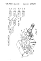
- FIG. 1 is a cross-sectional view of the fiber optic coupler used as a multiplexer in the present invention, showing a pair of fiber optic strands mounted in respective arcuate grooves of respective bases;
- FIGS. 2 and 3 are cross-sectional views of the coupler of FIG. 1, taken along lines 2--2 and 3--3, respectively;
- FIG. 4 is a perspective view of the lower base of the coupler of FIG. 1 separated from the other base to show its associated fiber mounting and the oval-shaped facing surface of the fiber;
- FIG. 5 is a schematic diagram showing the evanescent fields of the pair of fibers overlapping at the interaction region
- FIG. 6 is a schematic drawing of the coupler of FIG. 1 illustrating the radius of curvature, core spacing, and interaction length, as parameters of the coupler;
- FIG. 7 is a schematic drawing of an "equivalent" coupler
- FIG. 8 is a graph of normalized coupled power for a light signal of a given wavelength as a function of interaction length for a given fiber core spacing
- FIG. 9 is a graph of normalized coupled power for light signals of wavelengths identical to that of FIG. 8 as a function of interaction length for another fiber core spacing;
- FIG. 10 is a graph of normalized coupled power for light of a given wavelength as a function of minimum fiber core spacing (spacing surfaces superimposed);
- FIG. 11 is a graph of effective interaction length versus fiber radius of curvature for a coupler having a minimum spacing of 5 microns;
- FIG. 12 is a graph of effective interaction length as a function of signal wavelength for a pair of couplers having a minimum separation of 5 microns and fiber curvature radii of 25 and 100 centimeters;
- FIG. 13 is a schematic representation of the oval-shaped surfaces of the fibers after polishing, showing the facing surfaces laterally offset;
- FIG. 14 is a schematic illustration showing the physical relationship in a first orthogonal direction of two superimposed fibers in a coupler
- FIG. 15 is a schematic diagram of the fibers of FIG. 14 taken in a direction orthogonal to that of FIG. 14;
- FIG. 16 is a schematic illustration similar to FIG. 14 for offset fibers
- FIG. 17 is a schematic illustration similar to FIG. 15 for the offset fibers of FIG. 16;
- FIG. 18 is a graph showing the effective interaction length of a coupler, according to the present invention, as a function of horizontal fiber offset for a pair of couplers having a minimum fiber spacing of 5 microns, at a wavelength of 633 nm, and radii of 25 and 100 centimeters;
- FIG. 19 is a graph of normalized coupled power as a function of lateral offset for a first minimum fiber core spacing
- FIG. 20 is a graph of normalized coupled power as a function of lateral offset for a second fiber core spacing
- FIG. 21 is a graph of normalized coupled power as a function of lateral offset for a third fiber core spacing
- FIG. 22 is a graph of (a) normalized coupled power as a function of lateral offset and (b) throughput loss as a function of lateral offset for one exemplary coupler showing that the throughput loss is substantially constant over substantially the entire range of normalized coupled power;
- FIG. 23 is a schematic representation of the facing surfaces of the fiber, showing the facing surfaces longitudinally offset
- FIG. 24 is a schematic representation of the facing surfaces of the fibers, showing these facing surfaces rotationally offset;
- FIG. 25 is a schematic illustration of the E field overlap between coupled fibers in the coupler of the present invention with short wavelengths
- FIG. 26 is similar to FIG. 25 and shows the E field overlap for intermediate wavelengths
- FIG. 27 is similar to FIGS. 25 and 26 and shows the E field overlap for long wavelengths
- FIG. 28 is a plot of average power density at the core/cladding boundary and core power/total power as a function of normalized frequency
- FIG. 29 is a chart of coupling length versus signal wavelength for a type 1 fiber coupler having a fiber radius of 25 centimeters;
- FIG. 30 is a chart of coupling length versus signal wavelength for a type 2 fiber coupler having a fiber radius of 25 centimeters;
- FIG. 31 is a schematic illustration of the multiplexer of the present invention.
- FIG. 32 is a chart showing relative coupled power versus signal wavelength for a type 1 fiber coupler having a minimum fiber spacing of 4 microns, an offset of 0 micron, and a fiber radius of 25 centimeters;
- FIG. 33 is a chart of relative coupled power versus signal wavelengths similar to FIG. 32 but with a fiber radius of 200 centimeters;
- FIG. 34 is a chart of the quotient of the interaction length divided by the coupling length versus signal wavelength for a variety of couplers having different minimum fiber spacings;
- FIG. 35 is a chart of relative coupled power versus signal wavelength for a type 1 fiber coupler having a minimum fiber spacing of 4 microns, a fiber radius of 200 centimeters, and a selectable fiber offset;
- FIG. 36 is a perspective view of a tuning device having micrometers for adjusting the offset of the facing surfaces to tune the coupler to a desired coupling efficiency
- FIG. 37 is a schematic illustration of a multiple wavelength multiplexing system using the multiplexing coupler of the present invention.
- the coupler 10 of the present invention includes two strands 12A and 12B of a single mode fiber optic material mounted in longitudinal arcuate grooves 13A and 13B, respectively, formed in optically flat, confronting surfaces 14A and 14B, respectively, of rectangular bases or blocks 16A and 16B, respectively.
- the block 16A with the strand 12A mounted in the groove 13A will be referred to as the coupler half 10A
- the block 16B with the strand 12B mounted in the groove 13B will be referred to as the coupler half 10B.
- Each of the strands 12A and 12B comprise a commercially available fiber of quartz glass which is doped to have a central core and an outer cladding.
- the strands 12A and 12B are single mode fibers, which typically have a core diameter on the order of 10 microns or less and a cladding diameter on the order of 125 microns. In the embodiment disclosed, the diameter of the strands 12 and their respective cores are exaggerated.
- the arcuate grooves 13A and 13B have a radius of curvature which is very large compared to the diameter of the fibers 12, and have a width slightly larger than the fiber diameter to permit the fibers 12, when mounted therein, to conform a path defined by the bottom walls of the grooves 13.
- the depth of the grooves 13A and 13B varies from a minimum at the center of the blocks 16A and 16B, respectively, to a maximum at the edges of the blocks 16A and 16B, respectively.
- the grooves 13 are illustrated as being rectangular in cross-section, however, it will be understood that other suitable cross-sectional contours which will accommodate the fibers 12 may be used alternatively, such as a U-shaped cross-section or a V-shaped cross-section.
- the depth of the grooves 13 which mount the strands 12 is less than the diameter of the strands 12, while at the edges of the blocks 16, the depth of the grooves 13 is preferably at least as great as the diameter of the strands 12.
- Fiber optic material was removed from each of the strands 12A and 12B to form the respective oval-shaped planar surfaces 18A, 18B, which are coplanar with the confronting surfaces 17A, 17B, respectively. These surfaces 18A, 18B will be referred to herein as the fiber "facing surfaces".
- the amount of fiber optic material removed increases gradually from zero towards the edges of the block 16 to a maximum towards the center of the block 16. This tapered removal of the fiber optic material enables the fibers to converge and diverge gradually, which is advantageous for avoiding backward reflection and excess loss of light energy.
- the coupler halves 10A and 10B are identical, and are assembled by placing the confronting surfaces 14A and 14B of the blocks 16A and 16B together, so that the facing surfaces 18A and 18B of the strands 12A and 12B are in facing relationship.
- index matching substance such as index matching oil, is provided between the confronting surfaces 14.
- This substance has a refractive index approximately equal to the refractive index of the cladding, and also functions to prevent the optically flat surfaces 14 from becoming permanently locked together.
- the oil is introduced between the blocks 16 by capillary action.
- An interaction region 32 is formed at the junction of the strands 12, in which light is transferred between the strands by evanescent field coupling. It has been found that, to insure proper evanescent field coupling, the amount of material removed from the fibers 12 must be carefully controlled so that the spacing between the core portions of the strands 12 is within a predetermined "critical zone".
- the evanescent fields extend into the cladding and decrease rapidly with distance outside their respective cores. Thus, sufficient material should be removed to permit each core to be positioned substantially within the evanescent field of the other. If too little material is removed, the cores will not be sufficiently close to permit the evanescent fields to cause the desired interaction of the guided modes, and thus, insufficient coupling will result.
- each strand receives a significant portion of the evanescent field energy from the other strand, and good coupling is achieved without significant energy loss.
- the critical zone is illustrated schematically in FIG. 5 as including that area, designated by the reference numeral 33, in which the evanescent fields, designated by reference numerals 34A and 34B, of the fibers 12A and 12B, respectively, overlap with sufficient strength to provide coupling, i.e., each core is within the evanescent field of the other.
- mode perturbation occurs within the area 33 when the cores are brought too close together.
- the critical zone is defined as that area in which the evanescent fields 34 overlap with sufficient strength to cause coupling without substantial mode perturbation induced power loss.
- the critical zone for a particular coupler is dependent upon a number of interrelated factors such as the parameters of the fiber itself and the geometry of the coupler. Further, for a single mode fiber having a step-index profile, the critical zone can be quite narrow. In a single mode fiber coupler of the type shown in FIGS. 1-4, for example, the required center-to-center spacing between the strands 12 at the center of the coupler is typically less than a few (e.g., 2-3) core diameters.
- the strands 12A and 12B are (1) identical to each other, (2) have the same radius of curvature at the interaction region 32, and (3) have an equal amount of fiber optic material removed therefrom to form their respective facing surfaces 18A and 18B.
- the fibers 12 are symmetrical, through the interaction region 32, in the plane of the facing surfaces 18, so that the facing surfaces 18 are coextensive if superimposed. This insures that the two fibers 12A and 12B will have the same propagation characteristics at the interaction region 32, and thereby avoids coupling attenuation associated with dissimilar propagation characteristics.
- the blocks or bases 12 may be fabricated of any suitable rigid material.
- the bases 12 comprise generally rectangular blocks of fused quartz glass approximately 1 inch long, 1 inch wide, and 0.4 inch thick.
- the fiber optic strands 12 are secured in the slots 13 by suitable cement 38, such as epoxy glue.
- suitable cement 38 such as epoxy glue.
- One advantage of the fused quartz blocks 16 is that they have a coefficient of thermal expansion similar to that of glass fibers, and this advantage is particularly important if the blocks 16 and fibers 12 are subjected to any heat treatment during the manufacturing process.
- Another suitable material for the block 16 is silicon, which also has excellent thermal properties for this application.
- the coupler 10 includes four ports, labeled A, B, C, and D in FIG. 1.
- ports A and C which correspond to strands 12A and 12B, respectively, are on the left-hand side of the coupler 10
- the ports B and D which correspond to the strands 12A and 12B, respectively, are on the right-hand side of the coupler 10.
- input light is applied to port A. This light passes through the coupler and is output at port B and/or port D, depending upon the amount of power that is coupled between the strands 12.
- the term "normalized coupled power" is defined as the ratio of the coupled power to the total output power.
- the normalized coupled power would be equal to the ratio of the power at port D to the sum of the power output at ports B and D. This ratio is also referred to as the "coupling efficiency", and when so used is typically expressed as a percent.
- the corresponding coupling efficiency is equal to the normalized coupled power times 100.
- tests have shown that the coupler 10 has a coupling efficiency of up to 100%.
- the coupler 10 may be "tuned” to adjust the coupling efficiency to any desired value between zero and the maximum.
- the coupler 10 is highly directional, with substantially all of the power applied at one side of the coupler being delivered to the other side of the coupler.
- the coupler directivity is defined as the ratio of the power at port D to the power at port C, with the input applied to port A. Tests have shown that the directionally coupled power (at port D) is greater than 60 db above the contra-directionally coupled power (at port C).
- the coupler directivity is symmetrical. That is, the coupler operates with the same characteristics regardless of which side of the coupler is the input side and which side is the output side. Moreover, the coupler 10 achieves these results with very low throughput losses.
- the throughput loss is defined as the ratio of the total output power (ports B and D) to the input power (port A) subtracted from one (i.e., 1-(P B +P D )/P A ).
- Experimental results show that throughput losses of 0.2 db have been obtained, although losses of 0.5 db are more common. Moreover, these tests indicate that the coupler 10 operates substantially independently of the polarization of the input light applied.
- the coupler 10 operates on evanescent field coupling principles in which guided modes of the strands 12 interact, through their evanescent fields, to cause light to be transferred between the strands 12. As previously indicated, this transfer of light occurs at the interaction region 32.
- the amount of light transferred is dependent upon the proximity and orientation of the cores, as well as the effective length of the interaction region 32. As will be described in detail below, the amount of light transferred is also dependent of the wavelength of the light.
- the length of the interaction region 32 is, in turn, dependent upon the radius of curvature of the fibers 12, and, to a limited extent, the core spacing, although it has been found that the effective length of the interaction region 32 is substantially independent of core spacing.
- the coupling length is a function of core spacing, as well as wavelength.
- the effective interaction region is approximately one millimeter long at a light signal wavelength of 633 nm. Because the coupling length at 633 nm is also one millimeter in such a coupler, the light makes only one transfer between the strands 12 as it travels through the interaction region 32. However, if the length of the interaction region 32 is increased, or core spacing decreased, a phenomenon referred to herein as "overcoupling" will occur, since the coupling length is shorter than the effective interaction length.
- the light will transfer back to the strand from which it originated.
- the effective interaction length becomes a greater multiple of the coupling length, and the light transfers back to the other strand.
- the light may make multiple transfers back and forth between the two strands 12 as it travels through the region 32, the number of such transfers being dependent on the length of the interaction region 32, the light wavelength (as described below), and the core spacing.
- FIG. 6 shows a schematic representation of the coupler 10 of FIG. 1.
- the cores of fibers 12A and 12B are shown as gradually converging to a minimum spacing, labeled H, at the center of the coupler and diverging towards the edges of the coupler.
- the effective interaction length is labeled L and the radius of curvature of the strands 12A and 12B is labeled R. As indicated above, it has been found that, while the effective interaction length L is a function of the radius of curvature R, it is substantially independent of the minimum spacing H between the fibers 12.
- the coupler, illustrated in FIG. 6, to be analyzed as an "equivalent" coupler comprising two parallel waveguides, separated through an interaction length L (equal to the effective interaction length L of the coupler of FIG. 6), by a spacing H equal to the spacing H of FIG. 6, as shown in FIG. 7.
- FIG. 8 shows a sinusoidal curve 40 whil illustrates that the coupled power P C varies sinusoidally as a function of the interaction length L for a given fiber spacing H1 and a given wavelength.
- the coupler power is approximately 50% when the interaction length is equal to L1, and increases to 100% when the interaction length increases to L2.
- L2 equals the coupling length for this given wavelength.
- the amount of coupling may be varied by changing the length L of the interaction region of the "equivalent coupler" of FIG. 7.
- the effect of decreasing the spacing H between the fibers of this "equivalent coupler" is to increase the strength of the coupling, and thus, increase the amount of light transferred over a given interaction length L, as shown by comparing the sinusoidal curve 42 of FIG. 9 with the sinusoidal curve of FIG. 8.
- the coupled power may be 100% at interaction length L1 in FIG. 9, as compared to 50% for the same interaction length L1 in FIG. 8.
- this change in spacing effectively reduces the coupling length for the given wavelength from L2 (FIG. 8) to L1 (FIG. 9).
- the curve 42 then begins to demonstrate overcoupling and the coupled power decreases to 50% at interaction length L2.
- the curve 42 indicates that the coupled power is again 100%.
- the coupling length may be adjusted by changing the fiber core spacing.
- the relationship between the minimum fiber spacing H and the coupled power P C for a given interaction length L of the "equivalent coupler" of FIG. 7 and a given light wavelength is illustrated in FIG. 10 by the curve 44.
- the normalized coupled power oscillates between 0 and 1 with increasing frequency as the coupling length is shortened by decreasing the core spacing H.
- the reference points a, b, and c on the curve H were chosen somewhat arbitrarily to indicate normalized coupled power of 0.5, 1.0, and 0.25, respectively. It will be recognized that at point "a”, 50% of the power is coupled from one fiber to the other. At point “b”, full coupling is achieved, and 100% of the optical power is transferred between the strands.
- Point "c" represents an overcoupled condition wherein the coupled power has decreased from full coupling to 25%.
- the interaction length of the coupler is most advantageously analyzed through the use of an "equivalent coupler", shown in FIG. 7, wherein the minimum spacing H is identical to the minimum spacing H of the actual fiber, but the "effective interaction length" of the actual fiber of FIG. 6 is equal to the actual interaction length of the "equivalent coupler” of FIG. 7.
- the effective interaction length L can be considered as independent of the minimum fiber spacing H of FIG. 6.
- FIG. 12 The effect of signal wavelengths on effective interaction lengths (FIG. 6) is illustrated in FIG. 12. In this figure, the interaction length is seen to increase more or less linearly with increasing wavelengths.
- the term “tuning” is defined as translating the fibers 12 relative to each other to adjust the power coupled therebetween. Such translation of the fibers 12 is accomplished by sliding the planar facing surfaces 18 relative to each other, so that they are offset, rather than superimposed. That is, the fibers 12 are mutually displaced in the plane of the planar facing surfaces. Viewed another way, such translation occurs when respective planes in which each of the fibers lie, are displaced relative to each other.
- the facing surfaces 18 are offset laterally.
- laterally offset means sliding the facing surfaces 18 laterally from their superimposed position to increase the spacing between the fiber cores, while maintaining a substantially parallel relationship between the fibers 12.
- Such lateral offset of the facing surfaces 18 is illustrated schematically in FIG. 13.
- the effect of such lateral offset is, of course, to change the spacing between the cores of the fibers 12.
- the interaction length is also effected.
- FIGS. 14 and 15 schematically represents two views (parallel and perpendicular to the fiber plane) for a superimposed configuration analyzed previously.
- the minimum fiber spacing becomes (H 0 2 +Y 2 ) 1/2 , whereby Y is the lateral offset, but also the direction of this minimum spacing, shown by the dashed line in FIG. 17, no longer lies in the plane of the fibers.
- a new axis, ⁇ , shown in FIG. 17, is skewed relative this plane. When viewed from the direction of this ⁇ axis, the fiber curvature changes, and the projected radius of curvature is larger than that of the real radius R.
- FIG. 18 shows that, with increasing fiber offset, the coupler interaction length increases.
- the effective interaction length L (FIG. 6) at a given signal wavelength is found to depend primarily on the radius of curvature of the fibers.
- the dependence on minimum fiber spacing H is, for all practical purposes, negligible. Since signals with different wavelengths have different penetration depths into the cladding, there is a dependence of interaction length on signal wavelengths, in that the interaction length increases with increasing wavelengths.
- the geometry of the curved fiber coupler induces an increase in the effective radius of curvature of each fiber and thereby the interaction length with increasing lateral offset of the fibers.
- the effective interaction length between the curved fibers of FIG. 6 in a superimposed configuration is set at fabrication by the choice of a fiber radius of curvature R.
- the curve 46 of FIG. 19 graphically illustrates the effect of laterally offsetting the fiber facing surfaces 18 for a coupler having a minimum edge-to-edge core spacing H equal to "a" (FIG. 10) and a given wavelength light.
- the normalized coupled power will be equal to 0.5, as required by the curve 44 of FIG. 10.
- the facing surfaces 18 of the fibers 12 are laterally offset in either direction to increase the spacing between the cores, the coupled power gradually decreases to zero.
- the effect of lateral fiber offset upon normalized coupled power for a coupler having an edge-to-edge core spacing equal to "b" (FIG. 10) and the same light wavelength is shown.
- the normalized coupled power is 1.0, as required by the curve 44 of FIG. 10, however, as the facing surfaces 18 of the fibers 12 are laterally offset in either direction, the coupled power gradually decreases.
- the curve 50 of FIG. 21 shows coupled power as a function of relative fiber offset for a core spacing equal to "c" (FIG. 10) and the same light wavelength, which, as will be recalled, represents an overcoupled condition. (i.e., the effective interaction length, exceeds the coupling length.) From this curve 50, it may be seen that, when the facing surfaces 18 of the fibers 12 are superimposed, the normalized coupled power is 0.25. As the core spacing is increased by sliding the facing surfaces 18 so that they are laterally offset, the normalized coupled power initially increases to 1.0 as the effective interaction length decreases to equal the coupling length, and then decreases toward zero when the core spacing is further increased.
- the coupled power decreases to zero at substantially the same lateral offset, assuming that the physical parameters and light wavelengths corresponding to these figures are identical except for their fiber spacing at zero offset.
- the curves 46, 48, and 50 of the FIGS. 19, 20, and 21, respectively it may be seen that the respective slopes of these curves tend to increase as the core spacing decreases.
- the sensitivity of the coupler to lateral offset is higher for a coupler having the characteristics shown in FIG. 21 than couplers having the characteristics shown in either FIG. 19 or 20.
- FIG. 22 shows, for this exemplary coupler, a graph of throughput loss, designated by the reference numeral 60, and a graph of the normalized coupler power, designed by the reference numeral 62, both as a function of lateral offset of the facing surfaces 18.
- the two horizontal broken lines drawn through the center of FIG. 14 provide the upper and lower boundaries of an 0.2 db power loss band. It may be seen that the power loss curve 60 is within this band for lateral offsets up to about 12 microns in either direction. Further, it may be seen that, at a 12-micron lateral offset, the normalized coupled power is approximately 0.1. Thus, for coupled power 0.1 and 1, the power loss is within about 0.2 db of the minimum power loss.
- the power loss band is within the 0.5-db band for fiber offsets of up to 15 microns, which corresponds to a coupled power of less than 0.05 (i.e., 5%).
- this coupler exhibits substantially constant throughput losses, i.e., within a relatively narrow power loss band width, throughout substantially the entire operating range of the device. Further, it is significant that the throughput losses are very low, and relatively constant for coupled power between 10% and 100%.
- the coupler characteristics may be changed by longitudinally offsetting the facing surfaces.
- longitudinal offsetting refers to translating the facing surfaces 18 from a superimposed position to an offset position in a direction parallel to the fibers 12, as illustrated schematically in FIG. 23.
- Such longitudinal offset in effect, increases the minimum core spacing of the fibers 12.
- the coupling characteristics of the coupler 10 may also be affected by rotating the facing surfaces 18 relative to each other, as this decreases the effective length of the interaction region.
- the term "rotationally offsetting” will be used to refer to translating the fibers, as illustrated schematically in FIG. 24, by rotating the facing surfaces 18 about a common axis, e.g., the axis 66.
- the effect of such rotational offsetting is similar to that described above for longitudinally offsetting the surfaces. That is, the coupler 10 is relatively insensitive to small rotational offsets, both in terms of changes in coupled power, as well as in throughput losses.
- the coupling length within the coupler 10 is the length required for light of a given wavelength to transfer completely from one fiber 12 to the other fiber 12. As was described, particularly in reference to FIGS. 8, 9 and 10, the coupling length is directly affected by the minimum fiber spacing H (FIG. 6). In addition, it has been found that a coupling length is a function of the light wavelength. As described above, the penetration depth of the evanescent field of the unperturbed fiber mode inside the fiber cladding increases with increased wavelength.
- FIGS. 25,26, and 27 show the magnitude of the evanescent field for each of two closely spaced optical fibers.
- a poor overlap exists between the evanescent fields E1 and E2 because the evanescent fields at such wavelengths are mostly confined near the fiber core (depicted by the broken lines), that is, the modes are well guided and well confined in the respective waveguides.
- the signal wavelength is increased, as shown in FIG. 26, the evanescent fields E1 and E2 extend further away from the fiber cores and mode overlap increases.
- the coupling coefficient likewise increases, since this coefficient is the result of an integration through the core of the fiber (cross-hatched section of FIGS.
- FIG. 28 This phenomenon is further illustrated by FIG. 28 in which the normalized power carried by the cladding (or the core) and the power density at the core-cladding interface is plotted as a function of normalized frequency for a weakly guided fiber. It is clear that at longer wavelengths (lower frequencies), most of the mode is in the fiber cladding (weak guiding). It is also apparent that the power density (and the magnitude of the electric field) at the core-cladding boundary, or for that matter, at any radial position in the cladding, is maximum for a certain signal wavelength. At shorter wavelengths, the energy distribution shifts toward the core (well guided mode), whereas at longer wavelengths, the energy spreads further out, and is thus reduced at any radial position in the core or cladding (loose guiding). The existence of a maximum coupling wavelength in parallel fiber couplers is a consequence of this maximum in the modal power density curve.
- the coupling length (the length required for a complete transfer of energy between fibers) exhibits a minimum, for a given fiber spacing H, at this maximum coupling wavelength. Furthermore, the wavelength of optimum coupling or shortest coupling length shifts toward the infrared as the fiber spacing is increased.
- the dependence of coupling length on signal wavelengths is represented for two different types of fibers in FIGS. 29 and 30.
- the type 1 fiber illustrated in FIG. 29 has a fiber radius of two microns, a core refractive index of 1,460, and a cladding refractive index of 1.4559.
- the type 11 fiber, illustrated in FIG. 30, has a core radius of 3 microns, a core refractive index of 1.458, and cladding refractive index of 1.4551. From these figures, it can be seen that, for a given fiber spacing H, the coupling length is seen to first decrease when the signal wavelength increases from one end of the visible spectrum toward the infrared, and then increases as the wavelength is further increased. Thus, for a given fiber spacing, there is a wavelength that has the shortest coupling length and this wavelength shifts toward the infrared as the fiber spacing is increased.
- FIG. 32 provides a plot of coupled power versus signal wavelength in the visible and near infrared spectrum for a particular coupler geometry. Because for this coupler configuration the effective interaction length of the coupler is an odd multiple of the coupling length for the wavelength 720 nm, but an even multiple of the coupling length for the wavelength 550 nm, the wavelength 720 nm will be 100% coupled, while the wavelength 550 nm will be effectively uncoupled. With different efficiencies, different wavelengths may be combined or separated. For instance, 590 nm and 650 nm may be separated or combined at an 80% efficiency.
- Virtually any pair of wavelengths may be efficiently combined or separated so long as the effective interaction length is an even multiple of the coupling length for one wavelength and an odd multiple for the coupling length for the other wavelength.
- the resolution of the multiplexer is enhanced. Because, as shown previously, the effective interaction length is largely a function of the radius of curvature R of the coupler 10, the multiplexer resolution may be enhanced by increasing the radius of curvature R. Provided that the interaction length of the coupler is large enough, virtually any two signals may be exactly mixed or separated, regardless of how closely spaced their wavelengths are.
- the coupling lengths show a minimum in the spectral range of interest for typical single mode fibers, care must be taken to operate a multiplexer away from this low resolution point.
- the position of the minimum coupling length, as described in reference to FIGS. 29 and 30, depends upon the minimum fiber spacing. This parameter can therefore be used to properly bias a coupler for high coupling dispersion in a wavelength range of interest.
- the interaction length is a function of wavelength, and the resolution is approximately proportional to (R) -1/2 .
- R increases, the effective interaction length increases, and becomes a higher multiple of the coupling length, improving resolution.
- FIG. 33 which is comparable to the graph of FIG. 32, except that the radius of curvature has been increased to 200 centimeters.
- the effective interaction length was shown to be a function of wavelength. Since, as described in reference to FIGS. 29 and 30 the coupling length is also affected by wavelength, the multiple number of coupling lengths within the effective interaction length, which defines the multiplexer resolution, is affected by both of these wavelength dependencies.
- FIG. 34 shows that the quotient of the effective interaction length divided by the coupling length presents a maximum value, and both this maximum value and the wavelength at which it occurs depend on the minimum fiber spacing H. As noted previously, it is difficult to obtain good resolution with a multiplexer operated near a maximum of one of the curves of FIG. 34, since the quotient near this region varies slowly with wavelength.
- the radius of curvature R can be selected to provide a frequency separation required ( ⁇ 1- ⁇ 2) for the pair of frequencies to be multiplexed. This relationship was previously explained, the effective interaction length being a function of the radius of curvature, and the odd/even multiple requirement for the coupling length for the two frequencies to be separated. It should be noted that a change in the radius of curvature R only scales the effective interaction length, but does not scale the coupling length. Thus, since the position of the maxima of the curves of FIG. 34 are a function of the positions of the minima of coupling length (FIGS. 29 and 30), a change in the radius R scales the curves of FIG. 34, without substantially offsetting their maxima.
- the resolution of a multiplexing coupler therefore depends on the two independent parameters, H (fiber spacing) and R (radius of curvature of the fibers).
- H fiber spacing
- R radius of curvature of the fibers
- the coupler may be tuned to precisely adjust the coupling lengths for the wavelengths of interest so that the effective interaction length is an even multiple of the coupling length of one wavelength and an odd multiple of the coupling length of the other wavelength. This is accomplished by offsetting the fibers, as was described in reference to FIGS. 16 and 17. Such an offset, as was described previously, has the effect of increasing the minimum fiber spacing H and increasing the effective radius of curvature of the fibers. If the required offset is small enough, it will not upset the multiplexer resolution. This stems from the fact that the separation H of a large radius coupler changes rapidly with fiber offset in comparison to changes in the effective radius of curvature with fiber offset.
- the minimum fiber spacing is chosen so that the frequencies of interest are away from a maxima of the curves of FIG. 34.
- the radius of curvature R is chosen to achieve the required resolution, that is, the radius of curvature should yield an interaction length which provides the necessary number of coupling lengths within the effective interaction length to provide the odd/even multiple relationship described above.
- the multiplexer is adjusted by offsetting the two fibers to increase the fiber spacing H, which affects the coupling at both wavelengths ⁇ 1 and ⁇ 2, without significantly modifying the wavelength resolution.
- the coupler 10 may be mechanically tuned in accordance with the foregoing concepts by means of a tuning device 70, shown in FIG. 36.
- the device 70 comprises a micrometer carriage 71 having a stepped U-shaped channel 72.
- the lower portion 74 of the channel 72 is narrower than the upper portion 76, and is sized to rigidly mount the coupler block 16B, with the bottom of the block 16B resting on the bottom of the channel 72.
- the step transition 79 between the upper portion 76 and lower portion 74 is below the confronting surfaces 14 of the block, so that the upper block 16A may be translated, in a direction perpendicular to the channel portion 76.
- the coupler 10 is oriented so that the strands 12 are in a direction parallel to the channel 72 to permit such translation to laterally offset the facing surfaces 18.
- a pair of cylindrically shaped retainers 78 are slidably mounted to project from one sidewall of the upper portion 76 of the channel 72. These retainers 78 are spring loaded to bear against one side of the block 16A. Differential micrometers 80 are mounted on the opposide sidewall of the channel upper portion 76. The micrometers 80 bear against the opposite side of the block 16A, so that the block 16A is held between the micrometers 80 and the spring biased retainers 78.
- the position of the block 16A may be adjusted relative to the block 16B to superimpose the fasing surfaces 18. Since the blocks 16 are comprised of transparent quartz, the relative positions of the facing surfaces 18 may be observed by utilizing a microscope. The surfaces 18 may also be laterally offset from their superimposed position, if desired, to tune the coupler 10 to the desired coupling efficiency, by rotating the micrometers 80. Once the coupler 10 has been tuned, the blocks 16 may, if desired, be clamped, bonded, or fused together to provide a coupler with a permanently or semi-permanently fixed offset.
- the device 70 may also be used to rotate the facing surfaces 18 relative to each other by turning one of the micrometers 80 to skew the blocks 16.
- FIG. 37 illustrates schematically the manner in which the multiplexing coupler of the present invention may be utilized to separate a larger plurality of signal wavelengths.
- a plurality of multiplexing couplers 100-112 are utilized.
- One input fiber of the coupler 100 is coupled to a fiber on which eight separate optical wavelengths are transmitted, represented by ⁇ 1 through ⁇ 8.
- the frequency separation of each pair of adjacent fibers i.e., ( ⁇ 1- ⁇ 2), ( ⁇ 2- ⁇ 3), ( ⁇ 3- ⁇ 4), etc., is equal, and will be designated ⁇ .
- the first multiplexing coupler 100 has a resolution equal to ⁇ and will thus couple wavelengths ⁇ 2, ⁇ 4, ⁇ 6, and ⁇ 8, but will leave virtually uncoupled the remaining wavelengths ⁇ 1, ⁇ 3, ⁇ 5, and ⁇ 7. These latter wavelengths are coupled to a fiber input of the coupler 102. Similarly, the wavelengths ⁇ 2, ⁇ 4, ⁇ 6, and ⁇ 8 are coupled to a fiber input of the coupler 104.
- the couplers 102 and 104 have a resolution equal to 2 ⁇ and thus separate input wavelengths spaced by 2 ⁇ onto separate output fibers. For example, the coupler 102 provides essentially no coupling of the wavelengths ⁇ 1 and ⁇ 5, but essentially complete coupling of the wavelengths ⁇ 3 and ⁇ 7.
- the fibers from the couplers 102,104 provide inputs to the couplers 106 through 112 which each have a resolution of 4 ⁇ and thus provide the final separation of the input wavelengths onto separate output fibers. It will be understood that the demultiplexing operation just described may be reversed by providing the input wavelengths ⁇ 1 through ⁇ 8 on the appropriate fibers, as shown in FIG. 37, of the couplers 106 through 112. This multiplexing operation will result in all of the wavelengths being combined on the single output fiber of the coupler 100.
- the resolutions described above may be adjusted in accordance with the previous description and the frequency for each multiplexing coupler may be selected by tuning the coupler.
- the resolution for the couplers 102 and 104 is identical, as is the resolution for the couplers 106 through 112.
- these groups of couplers are identical in construction but are tuned differently, requiring only three types of couplers for the apparatus shown in FIG. 36, to provide the frequency selection required.
- the fiber optic multiplexer described herein comprises a like single mode optical fiber having a portion joined to a length L of a like single mode optical fiber so that there is one hundred percent evanescent field coupling of one of a pair of wavelengths wherein the product of the coupling coefficient K and the length L equals ⁇ /2, and zero percent evanescent field coupling of the other of the pair of wavelengths wherein such product equals ⁇ .
Landscapes
- Physics & Mathematics (AREA)
- General Physics & Mathematics (AREA)
- Optics & Photonics (AREA)
- Optical Couplings Of Light Guides (AREA)
- Light Guides In General And Applications Therefor (AREA)
- Optical Communication System (AREA)
- Input Circuits Of Receivers And Coupling Of Receivers And Audio Equipment (AREA)
- Control Of Combustion (AREA)
- Mechanical Coupling Of Light Guides (AREA)
- Ultra Sonic Daignosis Equipment (AREA)
- Burglar Alarm Systems (AREA)
- Measurement And Recording Of Electrical Phenomena And Electrical Characteristics Of The Living Body (AREA)
Priority Applications (11)
| Application Number | Priority Date | Filing Date | Title |
|---|---|---|---|
| US06/319,301 US4556279A (en) | 1981-11-09 | 1981-11-09 | Passive fiber optic multiplexer |
| IL67162A IL67162A (en) | 1981-11-09 | 1982-11-02 | Method of and apparatus for multiplexing signals of different light wavelengths using optical fibres |
| AT82305851T ATE25555T1 (de) | 1981-11-09 | 1982-11-04 | Passiver lichtleitermultiplexer. |
| DE8282305851T DE3275488D1 (en) | 1981-11-09 | 1982-11-04 | Passive fiber optic multiplexer |
| EP82305851A EP0079196B1 (en) | 1981-11-09 | 1982-11-04 | Passive fiber optic multiplexer |
| AU90233/82A AU564991B2 (en) | 1981-11-09 | 1982-11-08 | Fibre optic multiplexer |
| JP57197416A JPS5888719A (ja) | 1981-11-09 | 1982-11-08 | フアイバ光マルチプレクサ |
| NO823710A NO823710L (no) | 1981-11-09 | 1982-11-08 | Passiv fiberoptisk multiplekser. |
| BR8206459A BR8206459A (pt) | 1981-11-09 | 1982-11-08 | Multiplexor de fibras opticas e processo de multiplexar um par de comprimentos de onda optica |
| CA000415105A CA1197931A (en) | 1981-11-09 | 1982-11-08 | Passive fiber optic multiplexer |
| KR8205069A KR900002513B1 (ko) | 1981-11-09 | 1982-11-09 | 수동 광학 섬유 멀티플렉서 |
Applications Claiming Priority (1)
| Application Number | Priority Date | Filing Date | Title |
|---|---|---|---|
| US06/319,301 US4556279A (en) | 1981-11-09 | 1981-11-09 | Passive fiber optic multiplexer |
Publications (1)
| Publication Number | Publication Date |
|---|---|
| US4556279A true US4556279A (en) | 1985-12-03 |
Family
ID=23241684
Family Applications (1)
| Application Number | Title | Priority Date | Filing Date |
|---|---|---|---|
| US06/319,301 Expired - Lifetime US4556279A (en) | 1981-11-09 | 1981-11-09 | Passive fiber optic multiplexer |
Country Status (11)
| Country | Link |
|---|---|
| US (1) | US4556279A (enExample) |
| EP (1) | EP0079196B1 (enExample) |
| JP (1) | JPS5888719A (enExample) |
| KR (1) | KR900002513B1 (enExample) |
| AT (1) | ATE25555T1 (enExample) |
| AU (1) | AU564991B2 (enExample) |
| BR (1) | BR8206459A (enExample) |
| CA (1) | CA1197931A (enExample) |
| DE (1) | DE3275488D1 (enExample) |
| IL (1) | IL67162A (enExample) |
| NO (1) | NO823710L (enExample) |
Cited By (73)
| Publication number | Priority date | Publication date | Assignee | Title |
|---|---|---|---|---|
| US4669816A (en) * | 1984-01-05 | 1987-06-02 | Standard Telephones And Cables Public Limited Company | Optical waveguide coupler |
| US4673270A (en) * | 1985-06-28 | 1987-06-16 | Amp Incorporated | Channel add/drop filter-coupler |
| US4681397A (en) * | 1985-06-28 | 1987-07-21 | Amp Incorporated | Optical switching arrangement |
| US4708421A (en) * | 1985-02-08 | 1987-11-24 | The Board Of Trustees Of The Leland Stanford Junior University | In-line fiber optic memory |
| US4717230A (en) * | 1985-06-28 | 1988-01-05 | Amp Incorporated | Optical eraser and node switch for an optical network |
| US4738511A (en) * | 1986-01-07 | 1988-04-19 | Litton Systems, Inc. | Molecular bonded fiber optic couplers and method of fabrication |
| US4738503A (en) * | 1985-02-08 | 1988-04-19 | The Board Of Trustees Of The Leland Stanford Junion University | In-line fiber optic memory |
| US4761832A (en) * | 1985-06-28 | 1988-08-02 | Amp Incorporated | Fiber optic switching network |
| WO1988009517A1 (en) * | 1987-05-22 | 1988-12-01 | Aster Corporation | Electro-optical converter |
| US4794598A (en) * | 1986-07-18 | 1988-12-27 | The Board Of Trustees Of The Leland Stanford Junior University | Synchronously pumped ring fiber Raman laser |
| US4810052A (en) * | 1986-01-07 | 1989-03-07 | Litton Systems, Inc | Fiber optic bidirectional data bus tap |
| US4815804A (en) * | 1985-02-08 | 1989-03-28 | The Board Of Trustees Of The Leland Stanford Junior University | In-line fiber optic memory and method of using same |
| US4828350A (en) * | 1986-01-17 | 1989-05-09 | The Board Of Trustees Of The Leland Stanford Junior University | Fiber optic mode selector |
| US4834481A (en) * | 1985-11-12 | 1989-05-30 | Gould Inc. | In-line single-mode fiber optic multiplexer/demultiplexer |
| US4842368A (en) * | 1987-08-17 | 1989-06-27 | American Telephone And Telegraph Company | N×N single-mode optical waveguide coupler |
| US4875969A (en) * | 1988-10-07 | 1989-10-24 | Eastman Kodak Company | Method of making a fiber optic array |
| US4880494A (en) * | 1988-10-07 | 1989-11-14 | Eastman Kodak Company | Method of making a fiber optic array |
| US4911526A (en) * | 1988-10-07 | 1990-03-27 | Eastman Kodak Company | Fiber optic array |
| US4915468A (en) * | 1987-02-20 | 1990-04-10 | The Board Of Trustees Of The Leland Stanford Junior University | Apparatus using two-mode optical waveguide with non-circular core |
| US4923275A (en) * | 1988-10-07 | 1990-05-08 | Eastman Kodak Company | Fiber optic array |
| US4938556A (en) * | 1983-11-25 | 1990-07-03 | The Board Of Trustees Of The Leland Stanford Junior University | Superfluorescent broadband fiber laser source |
| US4964131A (en) * | 1988-12-16 | 1990-10-16 | The Board Of Trustees Of The Leland Standford Junior University | Broadband optical fiber laser |
| US4976512A (en) * | 1989-04-05 | 1990-12-11 | Safaai Jazi Ahmad | Narrowband fiberoptic spectral filter formed from fibers having a refractive index with a W profile and a step profile |
| US5000530A (en) * | 1990-01-26 | 1991-03-19 | Seikoh Giken Co., Ltd. | Optical multiplexing/demultiplexing device with multiple ports |
| US5050950A (en) * | 1990-01-26 | 1991-09-24 | Seikoh Giken Co., Ltd. | Optical multiplexing/demultiplexing device of variable coupling type |
| US5074634A (en) * | 1990-01-26 | 1991-12-24 | Seikoh Giken Co., Ltd. | Optical multiplexing/demultiplexing device |
| US5100219A (en) * | 1990-10-05 | 1992-03-31 | Seikoh Giken Co., Ltd. | Optical fiber multiplexing/demultiplexing device for multiple-fiber ribbon of optical fibers and their fabrication method |
| US5106193A (en) * | 1990-08-09 | 1992-04-21 | The Board Of Trustees Of The Leland Stanford Junior University | Optical waveguide amplifier source gyroscope |
| US5108183A (en) * | 1989-08-31 | 1992-04-28 | The Board Of Trustees Of The Leland Stanford Junior University | Interferometer utilizing superfluorescent optical source |
| US5119229A (en) * | 1989-10-24 | 1992-06-02 | Societa' Cavi Pirelli S.P.A. | Amplifier for optical fiber telecommunication lines and optical fiber telecommunication lines incorporating said amplifier |
| WO1992015908A1 (en) * | 1991-03-05 | 1992-09-17 | Aster Corporation | Low cost one by eight singlemode optical fiber coupler |
| US5155621A (en) * | 1990-07-31 | 1992-10-13 | Fujitsu Limited | Optical fiber amplifier |
| US5161050A (en) * | 1990-02-12 | 1992-11-03 | Pirelli Cavi S.P.A. | Optical amplifier with bent, single-mode active fiber |
| US5257334A (en) * | 1991-09-24 | 1993-10-26 | Seikoh Giken Co., Ltd. | Ribbon type optical fiber connector |
| EP0439125B1 (en) * | 1990-01-26 | 1994-11-30 | Sumitomo Wiring Systems, Ltd. | Optical coupler and method of producing the same |
| US5636300A (en) * | 1994-12-12 | 1997-06-03 | Corning Incorporated | MxO multiplex demultiplex component |
| US5675679A (en) * | 1995-07-03 | 1997-10-07 | Sumitomo Wiring Systems, Ltd. | Light branching and coupling device |
| US5808764A (en) * | 1995-12-28 | 1998-09-15 | Lucent Technologies, Inc. | Multiple star, passive optical network based on remote interrogation of terminal equipment |
| US5949930A (en) * | 1997-07-23 | 1999-09-07 | Litton Systems, Inc. | Apparatus and method for scale factor stabilization in interferometric fiber optic rotation sensors |
| US6026205A (en) * | 1997-01-21 | 2000-02-15 | Molecular Optoelectronics Corporation | Compound optical waveguide and filter applications thereof |
| USRE36820E (en) * | 1995-01-13 | 2000-08-15 | Methode Electronics, Inc. | Removable optoelectronic module |
| US6179627B1 (en) | 1998-04-22 | 2001-01-30 | Stratos Lightwave, Inc. | High speed interface converter module |
| US6201704B1 (en) | 1995-01-13 | 2001-03-13 | Stratos Lightwave, Inc. | Transceive module with EMI shielding |
| US6203333B1 (en) | 1998-04-22 | 2001-03-20 | Stratos Lightwave, Inc. | High speed interface converter module |
| US6220878B1 (en) | 1995-10-04 | 2001-04-24 | Methode Electronics, Inc. | Optoelectronic module with grounding means |
| US6220873B1 (en) | 1999-08-10 | 2001-04-24 | Stratos Lightwave, Inc. | Modified contact traces for interface converter |
| EP1015855A4 (en) * | 1997-02-06 | 2001-10-24 | Optrand Inc | FUEL INJECTION UNITS WITH INTEGRATED FIBER OPTICAL PRESSURE SENSORS AND RELATED COMPENSATION AND MONITORING DEVICES |
| WO2002001267A1 (en) * | 2000-06-27 | 2002-01-03 | Oluma, Inc. | Integration of fibers on substrates fabricated with grooves |
| US6490391B1 (en) | 2000-07-12 | 2002-12-03 | Oluma, Inc. | Devices based on fibers engaged to substrates with grooves |
| US6501875B2 (en) | 2000-06-27 | 2002-12-31 | Oluma, Inc. | Mach-Zehnder inteferometers and applications based on evanescent coupling through side-polished fiber coupling ports |
| US6516131B1 (en) | 2001-04-04 | 2003-02-04 | Barclay J. Tullis | Structures and methods for aligning fibers |
| US6542663B1 (en) | 2000-09-07 | 2003-04-01 | Oluma, Inc. | Coupling control in side-polished fiber devices |
| GB2380257A (en) * | 2001-09-28 | 2003-04-02 | Protodel Internat Ltd | Monitor for an optical fibre |
| US6571035B1 (en) | 2000-08-10 | 2003-05-27 | Oluma, Inc. | Fiber optical switches based on optical evanescent coupling between two fibers |
| US20030099438A1 (en) * | 2001-11-21 | 2003-05-29 | Seiko Epson Corporation | Directional coupler and optical communication device |
| US6597833B1 (en) | 2000-06-27 | 2003-07-22 | Oluma, Inc. | Wavelength-division multiplexers and demultiplexers based on mach-zehnder interferometers and evanescent coupling |
| US6621952B1 (en) | 2000-08-10 | 2003-09-16 | Oluma, Inc. | In-fiber variable optical attenuators and modulators using index-changing liquid media |
| US6621951B1 (en) | 2000-06-27 | 2003-09-16 | Oluma, Inc. | Thin film structures in devices with a fiber on a substrate |
| US6625349B2 (en) | 2000-06-27 | 2003-09-23 | Oluma, Inc. | Evanescent optical coupling between a waveguide formed on a substrate and a side-polished fiber |
| US6719608B1 (en) | 2001-04-19 | 2004-04-13 | Oluma, Inc. | Fabrication of devices with fibers engaged to grooves on substrates |
| US6733166B2 (en) | 1997-12-09 | 2004-05-11 | Federal -Mogul World Wide, Inc. | Illuminated interior article system utilizing a Y-branch waveguide |
| US6744948B1 (en) | 2001-06-20 | 2004-06-01 | Oluma, Inc. | Fiber tap monitor based on evanescent coupling |
| US20040170358A1 (en) * | 2003-01-21 | 2004-09-02 | Fujikura Ltd. | Optical fiber coupler and optical fiber therefor |
| US6965721B1 (en) * | 2001-04-18 | 2005-11-15 | Tullis Barclay J | Integrated manufacture of side-polished fiber optics |
| US20050254750A1 (en) * | 2002-05-28 | 2005-11-17 | Edvardas Narevicius | Method and apparatus for optical mode division multiplexing and demultiplexing |
| US7090509B1 (en) | 1999-06-11 | 2006-08-15 | Stratos International, Inc. | Multi-port pluggable transceiver (MPPT) with multiple LC duplex optical receptacles |
| USRE40150E1 (en) | 1994-04-25 | 2008-03-11 | Matsushita Electric Industrial Co., Ltd. | Fiber optic module |
| CN100378478C (zh) * | 2006-04-28 | 2008-04-02 | 中国科学技术大学 | 多模光纤抛磨选模器 |
| US7576909B2 (en) | 1998-07-16 | 2009-08-18 | Imra America, Inc. | Multimode amplifier for amplifying single mode light |
| US7656578B2 (en) | 1997-03-21 | 2010-02-02 | Imra America, Inc. | Microchip-Yb fiber hybrid optical amplifier for micro-machining and marking |
| US20100220387A1 (en) * | 2002-10-02 | 2010-09-02 | Hee Gap Park | Superfluorescent fiber source with enhanced mean wavelength stability |
| CN113805280A (zh) * | 2021-10-05 | 2021-12-17 | 桂林电子科技大学 | 一种稳定且易制备的同轴双波导光纤侧向耦合器 |
| CN114074284A (zh) * | 2021-10-05 | 2022-02-22 | 桂林电子科技大学 | 一种可实现高精度批量侧抛光纤的装置 |
Families Citing this family (17)
| Publication number | Priority date | Publication date | Assignee | Title |
|---|---|---|---|---|
| JPS60500030A (ja) * | 1982-11-12 | 1985-01-10 | ザ・ボ−ド・オブ・トラスティ−ズ・オブ・ザ・レランド・スタンフォ−ド・ジュニア・ユニバ−シティ | ファイバ光学スイッチおよび離散的可変遅延線 |
| US4652079A (en) * | 1983-08-26 | 1987-03-24 | The Board Of Trustees Of The Leland Stanford Junior University | High speed pulse train generator |
| US4674830A (en) † | 1983-11-25 | 1987-06-23 | The Board Of Trustees Of The Leland Stanford Junior University | Fiber optic amplifier |
| GB2150703B (en) * | 1983-11-30 | 1987-03-11 | Standard Telephones Cables Ltd | Single mode fibre directional coupler |
| AU592066B2 (en) * | 1985-01-31 | 1990-01-04 | Ab Electronic Products Group Plc | Coupler for optical fibres |
| GB2170920B (en) * | 1985-02-12 | 1988-09-07 | Stc Plc | Beam splitter/combers |
| US4768854A (en) * | 1985-07-11 | 1988-09-06 | Raychem Corp. | Optical fiber distribution network including nondestructive taps and method using same |
| GB8519183D0 (en) * | 1985-07-30 | 1985-09-04 | British Telecomm | Optical fused couplers |
| JPS63175812A (ja) * | 1987-01-17 | 1988-07-20 | Nippon Telegr & Teleph Corp <Ntt> | 光フアイバカツプラ作製方法 |
| JPH07122683B2 (ja) * | 1987-02-21 | 1995-12-25 | 日本電信電話株式会社 | 光ファイバスターカップラの製造方法 |
| JPH03118506A (ja) * | 1989-10-02 | 1991-05-21 | Nikko Kapura:Kk | 光カプラとその製造方法 |
| CA2022367C (en) * | 1990-07-31 | 2002-12-17 | Kenneth O. Hill | Simplified wdm fused fiber coupler design |
| DE4228995C1 (en) * | 1992-08-31 | 1993-07-22 | Siemens Ag, 8000 Muenchen, De | Optical fibre coupling module - holds fibres in holders which have cutters to remove cladding when holders pushed together |
| JP3286972B2 (ja) * | 1992-12-25 | 2002-05-27 | キヤノン株式会社 | 波長分波装置及びそれを用いた波長多重通信システム |
| RU2120186C1 (ru) * | 1996-02-01 | 1998-10-10 | Российский Федеральный Ядерный Центр - Всероссийский Научно-Исследовательский Институт Экспериментальной Физики | Способ отвода световой энергии из оптического волокна |
| WO2010050975A1 (en) * | 2008-10-31 | 2010-05-06 | Hewlett-Packard Development Company, L.P. | Optical beam couplers and splitters |
| JP6059560B2 (ja) * | 2013-03-04 | 2017-01-11 | 日本電信電話株式会社 | マルチモード伝送用光増幅器 |
Citations (13)
| Publication number | Priority date | Publication date | Assignee | Title |
|---|---|---|---|---|
| GB1094639A (en) * | 1966-05-31 | 1967-12-13 | Standard Telephones Cables Ltd | A thin film surface wave mode dielectric waveguide |
| US3957341A (en) * | 1974-09-03 | 1976-05-18 | The United States Of America As Represented By The Secretary Of The Navy | Passive frequency-selective optical coupler |
| JPS5576308A (en) * | 1978-12-05 | 1980-06-09 | Nippon Telegr & Teleph Corp <Ntt> | Optical period waveform branching filter |
| US4243297A (en) * | 1979-06-27 | 1981-01-06 | International Communications And Energy, Inc. | Optical wavelength division multiplexer mixer-splitter |
| EP0038023A2 (en) * | 1980-04-11 | 1981-10-21 | The Board Of Trustees Of The Leland Stanford Junior University | Fiber optic directional coupler |
| US4300811A (en) * | 1978-08-28 | 1981-11-17 | Rca Corporation | III-V Direct-bandgap semiconductor optical filter |
| US4301543A (en) * | 1980-02-20 | 1981-11-17 | General Dynamics Corporation, Pomona Division | Fiber optic transceiver and full duplex point-to-point data link |
| US4307933A (en) * | 1980-02-20 | 1981-12-29 | General Dynamics, Pomona Division | Optical fiber launch coupler |
| US4315666A (en) * | 1979-03-19 | 1982-02-16 | Hicks Jr John W | Coupled communications fibers |
| US4335933A (en) * | 1980-06-16 | 1982-06-22 | General Dynamics, Pomona Division | Fiber optic wavelength demultiplexer |
| US4342499A (en) * | 1979-03-19 | 1982-08-03 | Hicks Jr John W | Communications tuning construction |
| US4343532A (en) * | 1980-06-16 | 1982-08-10 | General Dynamics, Pomona Division | Dual directional wavelength demultiplexer |
| US4362359A (en) * | 1979-04-21 | 1982-12-07 | U.S. Philips Corporation | Coupling device for coupling signals into and out of a transmission glass-fiber |
Family Cites Families (2)
| Publication number | Priority date | Publication date | Assignee | Title |
|---|---|---|---|---|
| JPS54101334A (en) * | 1978-01-27 | 1979-08-09 | Nippon Telegr & Teleph Corp <Ntt> | Optical fiber coupling element and production of the same |
| JPS56128904A (en) * | 1980-03-14 | 1981-10-08 | Nippon Telegr & Teleph Corp <Ntt> | Optical branching filter |
-
1981
- 1981-11-09 US US06/319,301 patent/US4556279A/en not_active Expired - Lifetime
-
1982
- 1982-11-02 IL IL67162A patent/IL67162A/xx not_active IP Right Cessation
- 1982-11-04 AT AT82305851T patent/ATE25555T1/de not_active IP Right Cessation
- 1982-11-04 EP EP82305851A patent/EP0079196B1/en not_active Expired
- 1982-11-04 DE DE8282305851T patent/DE3275488D1/de not_active Expired
- 1982-11-08 AU AU90233/82A patent/AU564991B2/en not_active Expired - Fee Related
- 1982-11-08 JP JP57197416A patent/JPS5888719A/ja active Granted
- 1982-11-08 NO NO823710A patent/NO823710L/no unknown
- 1982-11-08 CA CA000415105A patent/CA1197931A/en not_active Expired
- 1982-11-08 BR BR8206459A patent/BR8206459A/pt unknown
- 1982-11-09 KR KR8205069A patent/KR900002513B1/ko not_active Expired
Patent Citations (13)
| Publication number | Priority date | Publication date | Assignee | Title |
|---|---|---|---|---|
| GB1094639A (en) * | 1966-05-31 | 1967-12-13 | Standard Telephones Cables Ltd | A thin film surface wave mode dielectric waveguide |
| US3957341A (en) * | 1974-09-03 | 1976-05-18 | The United States Of America As Represented By The Secretary Of The Navy | Passive frequency-selective optical coupler |
| US4300811A (en) * | 1978-08-28 | 1981-11-17 | Rca Corporation | III-V Direct-bandgap semiconductor optical filter |
| JPS5576308A (en) * | 1978-12-05 | 1980-06-09 | Nippon Telegr & Teleph Corp <Ntt> | Optical period waveform branching filter |
| US4315666A (en) * | 1979-03-19 | 1982-02-16 | Hicks Jr John W | Coupled communications fibers |
| US4342499A (en) * | 1979-03-19 | 1982-08-03 | Hicks Jr John W | Communications tuning construction |
| US4362359A (en) * | 1979-04-21 | 1982-12-07 | U.S. Philips Corporation | Coupling device for coupling signals into and out of a transmission glass-fiber |
| US4243297A (en) * | 1979-06-27 | 1981-01-06 | International Communications And Energy, Inc. | Optical wavelength division multiplexer mixer-splitter |
| US4301543A (en) * | 1980-02-20 | 1981-11-17 | General Dynamics Corporation, Pomona Division | Fiber optic transceiver and full duplex point-to-point data link |
| US4307933A (en) * | 1980-02-20 | 1981-12-29 | General Dynamics, Pomona Division | Optical fiber launch coupler |
| EP0038023A2 (en) * | 1980-04-11 | 1981-10-21 | The Board Of Trustees Of The Leland Stanford Junior University | Fiber optic directional coupler |
| US4335933A (en) * | 1980-06-16 | 1982-06-22 | General Dynamics, Pomona Division | Fiber optic wavelength demultiplexer |
| US4343532A (en) * | 1980-06-16 | 1982-08-10 | General Dynamics, Pomona Division | Dual directional wavelength demultiplexer |
Non-Patent Citations (6)
| Title |
|---|
| Bergh et al., Electronics Letters, vol. 16, No. 7, Mar. 27, 1980, "Single-Mode Fibre Optic Directional Coupler", pp. 260-261. |
| Bergh et al., Electronics Letters, vol. 16, No. 7, Mar. 27, 1980, Single Mode Fibre Optic Directional Coupler , pp. 260 261. * |
| Kapany et al., J. of the Optical Society of America, vol. 58, No. 9, Sep. 1968, "Coherent Interactions between Optical . . . ", pp. 1176-1183. |
| Kapany et al., J. of the Optical Society of America, vol. 58, No. 9, Sep. 1968, Coherent Interactions between Optical . . . , pp. 1176 1183. * |
| Shiffner et al., Applied Physics, vol. 23, No. 1, Sep. 1980, "Double-Core Single-Mode Optical Fiber as Directional Coupler", pp. 41-45. |
| Shiffner et al., Applied Physics, vol. 23, No. 1, Sep. 1980, Double Core Single Mode Optical Fiber as Directional Coupler , pp. 41 45. * |
Cited By (90)
| Publication number | Priority date | Publication date | Assignee | Title |
|---|---|---|---|---|
| US4938556A (en) * | 1983-11-25 | 1990-07-03 | The Board Of Trustees Of The Leland Stanford Junior University | Superfluorescent broadband fiber laser source |
| US4669816A (en) * | 1984-01-05 | 1987-06-02 | Standard Telephones And Cables Public Limited Company | Optical waveguide coupler |
| US4815804A (en) * | 1985-02-08 | 1989-03-28 | The Board Of Trustees Of The Leland Stanford Junior University | In-line fiber optic memory and method of using same |
| US4708421A (en) * | 1985-02-08 | 1987-11-24 | The Board Of Trustees Of The Leland Stanford Junior University | In-line fiber optic memory |
| US4738503A (en) * | 1985-02-08 | 1988-04-19 | The Board Of Trustees Of The Leland Stanford Junion University | In-line fiber optic memory |
| US4673270A (en) * | 1985-06-28 | 1987-06-16 | Amp Incorporated | Channel add/drop filter-coupler |
| US4681397A (en) * | 1985-06-28 | 1987-07-21 | Amp Incorporated | Optical switching arrangement |
| US4717230A (en) * | 1985-06-28 | 1988-01-05 | Amp Incorporated | Optical eraser and node switch for an optical network |
| US4761832A (en) * | 1985-06-28 | 1988-08-02 | Amp Incorporated | Fiber optic switching network |
| US4834481A (en) * | 1985-11-12 | 1989-05-30 | Gould Inc. | In-line single-mode fiber optic multiplexer/demultiplexer |
| US4810052A (en) * | 1986-01-07 | 1989-03-07 | Litton Systems, Inc | Fiber optic bidirectional data bus tap |
| US4738511A (en) * | 1986-01-07 | 1988-04-19 | Litton Systems, Inc. | Molecular bonded fiber optic couplers and method of fabrication |
| US4828350A (en) * | 1986-01-17 | 1989-05-09 | The Board Of Trustees Of The Leland Stanford Junior University | Fiber optic mode selector |
| US4794598A (en) * | 1986-07-18 | 1988-12-27 | The Board Of Trustees Of The Leland Stanford Junior University | Synchronously pumped ring fiber Raman laser |
| US4915468A (en) * | 1987-02-20 | 1990-04-10 | The Board Of Trustees Of The Leland Stanford Junior University | Apparatus using two-mode optical waveguide with non-circular core |
| US5067787A (en) * | 1987-05-22 | 1991-11-26 | Aster Corporation | Electro-optical converter |
| US4844573A (en) * | 1987-05-22 | 1989-07-04 | Aster Corporation | Electro-optical converter including ridgid support for optical fiber coupler, telephone set using the coupler and method of making same |
| WO1988009517A1 (en) * | 1987-05-22 | 1988-12-01 | Aster Corporation | Electro-optical converter |
| US4842368A (en) * | 1987-08-17 | 1989-06-27 | American Telephone And Telegraph Company | N×N single-mode optical waveguide coupler |
| US4875969A (en) * | 1988-10-07 | 1989-10-24 | Eastman Kodak Company | Method of making a fiber optic array |
| US4880494A (en) * | 1988-10-07 | 1989-11-14 | Eastman Kodak Company | Method of making a fiber optic array |
| US4911526A (en) * | 1988-10-07 | 1990-03-27 | Eastman Kodak Company | Fiber optic array |
| US4923275A (en) * | 1988-10-07 | 1990-05-08 | Eastman Kodak Company | Fiber optic array |
| US4964131A (en) * | 1988-12-16 | 1990-10-16 | The Board Of Trustees Of The Leland Standford Junior University | Broadband optical fiber laser |
| US4976512A (en) * | 1989-04-05 | 1990-12-11 | Safaai Jazi Ahmad | Narrowband fiberoptic spectral filter formed from fibers having a refractive index with a W profile and a step profile |
| US5108183A (en) * | 1989-08-31 | 1992-04-28 | The Board Of Trustees Of The Leland Stanford Junior University | Interferometer utilizing superfluorescent optical source |
| US5119229A (en) * | 1989-10-24 | 1992-06-02 | Societa' Cavi Pirelli S.P.A. | Amplifier for optical fiber telecommunication lines and optical fiber telecommunication lines incorporating said amplifier |
| AU633150B2 (en) * | 1989-10-24 | 1993-01-21 | Corning O.T.I. S.P.A. | Amplifier for optical fiber telecommunication lines and optical fiber telecommunication lines incorporating said amplifier |
| US5050950A (en) * | 1990-01-26 | 1991-09-24 | Seikoh Giken Co., Ltd. | Optical multiplexing/demultiplexing device of variable coupling type |
| US5074634A (en) * | 1990-01-26 | 1991-12-24 | Seikoh Giken Co., Ltd. | Optical multiplexing/demultiplexing device |
| EP0439125B1 (en) * | 1990-01-26 | 1994-11-30 | Sumitomo Wiring Systems, Ltd. | Optical coupler and method of producing the same |
| US5000530A (en) * | 1990-01-26 | 1991-03-19 | Seikoh Giken Co., Ltd. | Optical multiplexing/demultiplexing device with multiple ports |
| US5161050A (en) * | 1990-02-12 | 1992-11-03 | Pirelli Cavi S.P.A. | Optical amplifier with bent, single-mode active fiber |
| US5155621A (en) * | 1990-07-31 | 1992-10-13 | Fujitsu Limited | Optical fiber amplifier |
| US5106193A (en) * | 1990-08-09 | 1992-04-21 | The Board Of Trustees Of The Leland Stanford Junior University | Optical waveguide amplifier source gyroscope |
| US5100219A (en) * | 1990-10-05 | 1992-03-31 | Seikoh Giken Co., Ltd. | Optical fiber multiplexing/demultiplexing device for multiple-fiber ribbon of optical fibers and their fabrication method |
| US5166994A (en) * | 1991-03-05 | 1992-11-24 | Aster Corporation | Low cost one by eight singlemode optical fiber coupler |
| WO1992015908A1 (en) * | 1991-03-05 | 1992-09-17 | Aster Corporation | Low cost one by eight singlemode optical fiber coupler |
| US5257334A (en) * | 1991-09-24 | 1993-10-26 | Seikoh Giken Co., Ltd. | Ribbon type optical fiber connector |
| USRE40154E1 (en) | 1994-04-25 | 2008-03-18 | Matsushita Electric Industrial Co., Ltd. | Fiber optic module |
| USRE40150E1 (en) | 1994-04-25 | 2008-03-11 | Matsushita Electric Industrial Co., Ltd. | Fiber optic module |
| US5636300A (en) * | 1994-12-12 | 1997-06-03 | Corning Incorporated | MxO multiplex demultiplex component |
| US6267606B1 (en) | 1995-01-13 | 2001-07-31 | Stratos Lightwave, Inc. | Removable transceiver module and receptacle |
| USRE36820E (en) * | 1995-01-13 | 2000-08-15 | Methode Electronics, Inc. | Removable optoelectronic module |
| US6201704B1 (en) | 1995-01-13 | 2001-03-13 | Stratos Lightwave, Inc. | Transceive module with EMI shielding |
| US5966484A (en) * | 1995-07-03 | 1999-10-12 | Sumitomo Wiring Systems, Ltd. | Light branching and coupling device |
| US5675679A (en) * | 1995-07-03 | 1997-10-07 | Sumitomo Wiring Systems, Ltd. | Light branching and coupling device |
| US6220878B1 (en) | 1995-10-04 | 2001-04-24 | Methode Electronics, Inc. | Optoelectronic module with grounding means |
| US5808764A (en) * | 1995-12-28 | 1998-09-15 | Lucent Technologies, Inc. | Multiple star, passive optical network based on remote interrogation of terminal equipment |
| US6026205A (en) * | 1997-01-21 | 2000-02-15 | Molecular Optoelectronics Corporation | Compound optical waveguide and filter applications thereof |
| EP1015855A4 (en) * | 1997-02-06 | 2001-10-24 | Optrand Inc | FUEL INJECTION UNITS WITH INTEGRATED FIBER OPTICAL PRESSURE SENSORS AND RELATED COMPENSATION AND MONITORING DEVICES |
| US7656578B2 (en) | 1997-03-21 | 2010-02-02 | Imra America, Inc. | Microchip-Yb fiber hybrid optical amplifier for micro-machining and marking |
| US5949930A (en) * | 1997-07-23 | 1999-09-07 | Litton Systems, Inc. | Apparatus and method for scale factor stabilization in interferometric fiber optic rotation sensors |
| US6733166B2 (en) | 1997-12-09 | 2004-05-11 | Federal -Mogul World Wide, Inc. | Illuminated interior article system utilizing a Y-branch waveguide |
| US6179627B1 (en) | 1998-04-22 | 2001-01-30 | Stratos Lightwave, Inc. | High speed interface converter module |
| US6203333B1 (en) | 1998-04-22 | 2001-03-20 | Stratos Lightwave, Inc. | High speed interface converter module |
| US7576909B2 (en) | 1998-07-16 | 2009-08-18 | Imra America, Inc. | Multimode amplifier for amplifying single mode light |
| US7090509B1 (en) | 1999-06-11 | 2006-08-15 | Stratos International, Inc. | Multi-port pluggable transceiver (MPPT) with multiple LC duplex optical receptacles |
| US6220873B1 (en) | 1999-08-10 | 2001-04-24 | Stratos Lightwave, Inc. | Modified contact traces for interface converter |
| US6556746B1 (en) | 2000-06-27 | 2003-04-29 | Oluma, Inc. | Integrated fiber devices based on Mach-Zehnder interferometers and evanescent optical coupling |
| WO2002001267A1 (en) * | 2000-06-27 | 2002-01-03 | Oluma, Inc. | Integration of fibers on substrates fabricated with grooves |
| US6516114B2 (en) | 2000-06-27 | 2003-02-04 | Oluma, Inc. | Integration of fibers on substrates fabricated with grooves |
| US6597833B1 (en) | 2000-06-27 | 2003-07-22 | Oluma, Inc. | Wavelength-division multiplexers and demultiplexers based on mach-zehnder interferometers and evanescent coupling |
| US6501875B2 (en) | 2000-06-27 | 2002-12-31 | Oluma, Inc. | Mach-Zehnder inteferometers and applications based on evanescent coupling through side-polished fiber coupling ports |
| US6621951B1 (en) | 2000-06-27 | 2003-09-16 | Oluma, Inc. | Thin film structures in devices with a fiber on a substrate |
| US6625349B2 (en) | 2000-06-27 | 2003-09-23 | Oluma, Inc. | Evanescent optical coupling between a waveguide formed on a substrate and a side-polished fiber |
| US6490391B1 (en) | 2000-07-12 | 2002-12-03 | Oluma, Inc. | Devices based on fibers engaged to substrates with grooves |
| US6690857B2 (en) | 2000-07-12 | 2004-02-10 | Oluma, Inc. | Fiber devices having side evanescent coupling port |
| US6621952B1 (en) | 2000-08-10 | 2003-09-16 | Oluma, Inc. | In-fiber variable optical attenuators and modulators using index-changing liquid media |
| US6571035B1 (en) | 2000-08-10 | 2003-05-27 | Oluma, Inc. | Fiber optical switches based on optical evanescent coupling between two fibers |
| US6542663B1 (en) | 2000-09-07 | 2003-04-01 | Oluma, Inc. | Coupling control in side-polished fiber devices |
| US6516131B1 (en) | 2001-04-04 | 2003-02-04 | Barclay J. Tullis | Structures and methods for aligning fibers |
| US6965721B1 (en) * | 2001-04-18 | 2005-11-15 | Tullis Barclay J | Integrated manufacture of side-polished fiber optics |
| US6869347B2 (en) | 2001-04-19 | 2005-03-22 | Oluma, Inc. | Fabrication of devices with fibers engaged to grooves on substrates |
| US6719608B1 (en) | 2001-04-19 | 2004-04-13 | Oluma, Inc. | Fabrication of devices with fibers engaged to grooves on substrates |
| US6744948B1 (en) | 2001-06-20 | 2004-06-01 | Oluma, Inc. | Fiber tap monitor based on evanescent coupling |
| GB2380257B (en) * | 2001-09-28 | 2005-03-23 | Protodel Internat Ltd | Monitor for an optical fibre |
| GB2380257A (en) * | 2001-09-28 | 2003-04-02 | Protodel Internat Ltd | Monitor for an optical fibre |
| US20030099438A1 (en) * | 2001-11-21 | 2003-05-29 | Seiko Epson Corporation | Directional coupler and optical communication device |
| US20060174657A1 (en) * | 2001-11-21 | 2006-08-10 | Seiko Epson Corporation | Method of manufacturing directional coupler |
| US7582233B2 (en) | 2001-11-21 | 2009-09-01 | Seiko Epson Corporation | Method of manufacturing directional coupler |
| US7609918B2 (en) * | 2002-05-28 | 2009-10-27 | Optun (Bvi) Ltd. | Method and apparatus for optical mode division multiplexing and demultiplexing |
| US20050254750A1 (en) * | 2002-05-28 | 2005-11-17 | Edvardas Narevicius | Method and apparatus for optical mode division multiplexing and demultiplexing |
| US20100220387A1 (en) * | 2002-10-02 | 2010-09-02 | Hee Gap Park | Superfluorescent fiber source with enhanced mean wavelength stability |
| US8254416B2 (en) | 2002-10-02 | 2012-08-28 | The Board Of Trustees Of The Leland Stanford Junior University | Superfluorescent fiber source with enhanced mean wavelength stability |
| US7450802B2 (en) | 2003-01-21 | 2008-11-11 | Fujikura Ltd. | Optical fiber coupler and optical fiber therefor |
| US20040170358A1 (en) * | 2003-01-21 | 2004-09-02 | Fujikura Ltd. | Optical fiber coupler and optical fiber therefor |
| CN100378478C (zh) * | 2006-04-28 | 2008-04-02 | 中国科学技术大学 | 多模光纤抛磨选模器 |
| CN113805280A (zh) * | 2021-10-05 | 2021-12-17 | 桂林电子科技大学 | 一种稳定且易制备的同轴双波导光纤侧向耦合器 |
| CN114074284A (zh) * | 2021-10-05 | 2022-02-22 | 桂林电子科技大学 | 一种可实现高精度批量侧抛光纤的装置 |
Also Published As
| Publication number | Publication date |
|---|---|
| CA1197931A (en) | 1985-12-10 |
| EP0079196B1 (en) | 1987-02-25 |
| KR840002526A (ko) | 1984-07-02 |
| IL67162A (en) | 1985-09-29 |
| IL67162A0 (en) | 1983-03-31 |
| JPH0519131B2 (enExample) | 1993-03-15 |
| ATE25555T1 (de) | 1987-03-15 |
| AU564991B2 (en) | 1987-09-03 |
| KR900002513B1 (ko) | 1990-04-16 |
| JPS5888719A (ja) | 1983-05-26 |
| NO823710L (no) | 1983-05-10 |
| AU9023382A (en) | 1983-05-19 |
| DE3275488D1 (en) | 1987-04-02 |
| EP0079196A1 (en) | 1983-05-18 |
| BR8206459A (pt) | 1983-09-27 |
Similar Documents
| Publication | Publication Date | Title |
|---|---|---|
| US4556279A (en) | Passive fiber optic multiplexer | |
| CA1251072A (en) | Fiber optic switch and discretely variable delay line | |
| US4560234A (en) | Fiber optic switchable coupler | |
| CA1246916A (en) | Coupled communications fibers | |
| US4493528A (en) | Fiber optic directional coupler | |
| US4673270A (en) | Channel add/drop filter-coupler | |
| EP0207980B1 (en) | Fiber-lens optical coupler | |
| US4601541A (en) | Fiber optic directional coupler | |
| EP0622650B1 (en) | Narrow band Mach-Zehnder filter | |
| US4779945A (en) | Directional coupler utilizing biconically tapered optical fibers and a method of making same | |
| US4946250A (en) | Compact wavelength filter integrated to a single-mode optical fiber | |
| EP0126065B1 (en) | Continuously variable fiber optic delay line | |
| US5943458A (en) | Mach-Zehnder interferometric devices with composite fibers | |
| US6049645A (en) | 1XN and NXN fiber optic couplers | |
| AU743093B2 (en) | Phased fiber array for multiplexing and demultiplexing | |
| US4444463A (en) | Glass fibers with transverse openings and methods of their production | |
| US6341186B1 (en) | Method and apparatus for the passband flattening of dense wavelength division optical filters | |
| EP0234665A2 (en) | Fibre-optic coupler | |
| EP1430342B1 (en) | Passband flattening in an arrayed waveguide grating | |
| EP0818694B1 (en) | Mach-zehnder interferometric devices with composite fibers | |
| WO2001037013A1 (en) | Fabrication of multiplexing and demultiplexing single-mode fiber optic couplers | |
| EP0241171A2 (en) | Optical couplers | |
| JPH08220370A (ja) | 光ファイバカプラ | |
| EP1318420A1 (en) | Optical coupler and arrayed waveguide grating (AWG) comprising the same | |
| EP1091222A2 (en) | Method of making Mach-Zehnder interferometric device with composite fibers |
Legal Events
| Date | Code | Title | Description |
|---|---|---|---|
| AS | Assignment |
Owner name: BOARD OF TRUSTEES OF THE LELAND STANFORD JUNIOR UN Free format text: ASSIGNMENT OF ASSIGNORS INTEREST.;ASSIGNORS:SHAW, HERBERT J.;DIGONNET, MICHEL J. F.;REEL/FRAME:003945/0559 Effective date: 19811106 Owner name: BOARD OF TRUSTEES OF THE LELAND STANFORD JUNIOR UN Free format text: ASSIGNMENT OF ASSIGNORS INTEREST;ASSIGNORS:SHAW, HERBERT J.;DIGONNET, MICHEL J. F.;REEL/FRAME:003945/0559 Effective date: 19811106 |
|
| STCF | Information on status: patent grant |
Free format text: PATENTED CASE |
|
| FEPP | Fee payment procedure |
Free format text: PAYOR NUMBER ASSIGNED (ORIGINAL EVENT CODE: ASPN); ENTITY STATUS OF PATENT OWNER: LARGE ENTITY |
|
| FPAY | Fee payment |
Year of fee payment: 4 |
|
| FEPP | Fee payment procedure |
Free format text: PAYER NUMBER DE-ASSIGNED (ORIGINAL EVENT CODE: RMPN); ENTITY STATUS OF PATENT OWNER: LARGE ENTITY Free format text: PAYOR NUMBER ASSIGNED (ORIGINAL EVENT CODE: ASPN); ENTITY STATUS OF PATENT OWNER: LARGE ENTITY |
|
| FPAY | Fee payment |
Year of fee payment: 8 |
|
| FPAY | Fee payment |
Year of fee payment: 12 |