US4549964A - Device for flushing obstructions from the reject head of a centrifugal separator - Google Patents
Device for flushing obstructions from the reject head of a centrifugal separator Download PDFInfo
- Publication number
- US4549964A US4549964A US06/500,207 US50020783A US4549964A US 4549964 A US4549964 A US 4549964A US 50020783 A US50020783 A US 50020783A US 4549964 A US4549964 A US 4549964A
- Authority
- US
- United States
- Prior art keywords
- plug
- reject
- chamber
- tube
- centrifugal separator
- Prior art date
- Legal status (The legal status is an assumption and is not a legal conclusion. Google has not performed a legal analysis and makes no representation as to the accuracy of the status listed.)
- Expired - Fee Related
Links
- 238000011010 flushing procedure Methods 0.000 title 1
- 239000012535 impurity Substances 0.000 claims abstract description 7
- 230000000903 blocking effect Effects 0.000 claims description 4
- 238000000034 method Methods 0.000 abstract description 10
- 238000004140 cleaning Methods 0.000 abstract description 7
- 239000000463 material Substances 0.000 abstract description 3
- XLYOFNOQVPJJNP-UHFFFAOYSA-N water Substances O XLYOFNOQVPJJNP-UHFFFAOYSA-N 0.000 abstract description 2
- 239000002245 particle Substances 0.000 description 3
- 239000000725 suspension Substances 0.000 description 3
- 239000004576 sand Substances 0.000 description 2
- 229920002678 cellulose Polymers 0.000 description 1
- 239000001913 cellulose Substances 0.000 description 1
- 238000010276 construction Methods 0.000 description 1
- 230000003247 decreasing effect Effects 0.000 description 1
- 238000001914 filtration Methods 0.000 description 1
- ZZUFCTLCJUWOSV-UHFFFAOYSA-N furosemide Chemical compound C1=C(Cl)C(S(=O)(=O)N)=CC(C(O)=O)=C1NCC1=CC=CO1 ZZUFCTLCJUWOSV-UHFFFAOYSA-N 0.000 description 1
- 239000007788 liquid Substances 0.000 description 1
- 239000002923 metal particle Substances 0.000 description 1
- 238000012544 monitoring process Methods 0.000 description 1
- JTJMJGYZQZDUJJ-UHFFFAOYSA-N phencyclidine Chemical class C1CCCCN1C1(C=2C=CC=CC=2)CCCCC1 JTJMJGYZQZDUJJ-UHFFFAOYSA-N 0.000 description 1
- 238000007790 scraping Methods 0.000 description 1
- 238000007789 sealing Methods 0.000 description 1
- 239000013049 sediment Substances 0.000 description 1
- 238000005507 spraying Methods 0.000 description 1
- 239000000126 substance Substances 0.000 description 1
- 239000002699 waste material Substances 0.000 description 1
- 239000002023 wood Substances 0.000 description 1
Images
Classifications
-
- D—TEXTILES; PAPER
- D21—PAPER-MAKING; PRODUCTION OF CELLULOSE
- D21D—TREATMENT OF THE MATERIALS BEFORE PASSING TO THE PAPER-MAKING MACHINE
- D21D5/00—Purification of the pulp suspension by mechanical means; Apparatus therefor
- D21D5/18—Purification of the pulp suspension by mechanical means; Apparatus therefor with the aid of centrifugal force
- D21D5/24—Purification of the pulp suspension by mechanical means; Apparatus therefor with the aid of centrifugal force in cyclones
-
- B—PERFORMING OPERATIONS; TRANSPORTING
- B04—CENTRIFUGAL APPARATUS OR MACHINES FOR CARRYING-OUT PHYSICAL OR CHEMICAL PROCESSES
- B04C—APPARATUS USING FREE VORTEX FLOW, e.g. CYCLONES
- B04C5/00—Apparatus in which the axial direction of the vortex is reversed
- B04C5/22—Apparatus in which the axial direction of the vortex is reversed with cleaning means
- B04C5/23—Apparatus in which the axial direction of the vortex is reversed with cleaning means using liquids
Definitions
- This invention is designed to flush obstructions from the reject head of a centrifugal separator without interrupting normal operation.
- Centrifugal separators are used mainly in the cellulose or paper industry for removing impurities, such as sand, bark, pieces of wood and metal particles etc., from pulp suspensions.
- the suspension to be purified is fed tangentially under pressure into the separator whereupon the mass starts to rotate. Centrifugal force separates particles of different weight or shape and forces them out to different positions in the vortex. Heavier substances, such as sand, go to the outermost position and move towards the the small-diameter exhaust pipe located at the apex of the separator cone.
- the purified pulp suspension accept flow, leaves the separator through a co-axial discharge pipe at the accept end where the centre of the vacuum is formed inside the separator.
- This invention has none of the above mentioned disadvantages. It is characteristic of the invention that it comprises a chamber, open at one end, fitted with a opening device for removing the bottom plug of the discharge end, as well as a discharge orifice for removing the rejected matter from the centrifugal separator.
- the invention is characterized by the fact that it is a separate device which can be attached to the obstructed separator by means of a quick-locking mechanism such as a threaded joint.
- the invention is characterized by the fact that the opening device consists of a sealed tube comprising an internal tightening rod fitted with grips for unscrewing and removing the plug; handles for operating the device are fitted at the opposite end.
- the invention is characterized by the fact that a tube or pipe can be attached to the discharge orifice of the chamber to remove the waste material or blocking sediment from the chamber when the plug is opened.
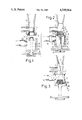
- FIG. 1 depicts the opening device and the reject end of a centrifugal separator before they are attached to one another
- FIG. 2 shows the opening device ready for operation and attached to the reject end of the centrifugal separator
- FIG. 3 shows the condition after the bottom plug has been opened and the material causing the blockage is flushed out.
- FIG. 1 shows the reject end (7) of the centrifugal separator comprising the reject outlet (1), cleaning orifice (2) and its plug (3).
- the opening device is composed of the frame or chamber (5), the opening device (8) for the plug and a discharge orifice (11).
- the opening end (4) forms a distinct unit comprising locking elements for the rod (9) and the tube (10) to be attached to the plug (3).
- FIG. 2 shows the opening device attached to the centrifugal separator by means of a quick-locking mechanism (6).
- the splines (15) in the locking or opening end (4) lock the tube (10) to the separator plug (3) so that the plug (3) can be rotated in either direction.
- the force applied to the friction ring (17) by the handle (13) via the rod (9) and the flange (14) expands the opening end (4) against the plug (3) so that the plug will not drop off when removed.
- FIG. 3 shows the plug (3) removed and the rejected material, indicated by an arrow, flowing from the reject orifice (2) and the impurities blocking the orifice (1) flowing out.
- a brush (18) and the opening for it (16) are also depicted in the figure.
- the cleaning operation does not interfere with the operation of the centrifugal separator or the plant.
- Cleaning efficiency can be checked and improved by scraping the reject orifice mechanically or by repeating the opening procedure with the plug (3) while at the same time monitoring the quality of the mass flowing through the discharge orifices (1) and (11).
Abstract
A device for cleaning obstructions from the reject end of a centrifugal separator without interrupting normal opertion. Modern small-sized separators, in particular, are liable to become blocked, and the usual method of removing the blockage is to use a water jet or pressurized air which is led to the obstructed reject end by various methods. The disadvantage associated with these methods is that the impurities removed by the jet partially contaminate the regular flow. This invention will help to avoid this because cleaning is effected by means of a device having a chamber into which the flow containing the rejected material is directed when the plug of the separator is opened. The chamber is fitted with a discharge orifice. In this way, the reversed flow removes the obstruction in the reject orifice, thus preventing it from contaminating the accept mass.
Description
This invention is designed to flush obstructions from the reject head of a centrifugal separator without interrupting normal operation.
Centrifugal separators (including hydro or liquid cyclones) are used mainly in the cellulose or paper industry for removing impurities, such as sand, bark, pieces of wood and metal particles etc., from pulp suspensions. The suspension to be purified is fed tangentially under pressure into the separator whereupon the mass starts to rotate. Centrifugal force separates particles of different weight or shape and forces them out to different positions in the vortex. Heavier substances, such as sand, go to the outermost position and move towards the the small-diameter exhaust pipe located at the apex of the separator cone. The purified pulp suspension, accept flow, leaves the separator through a co-axial discharge pipe at the accept end where the centre of the vacuum is formed inside the separator.
As the efficiency of centrifugal separators in removing small particles increases in proportion to the decreasing separator diameter, industry has moved over to small units.
One of the problems associated with modern small-diameter separators is the obstructing of the reject end. This is caused by over-sized particles or slowly accumulating deposits of impurities at the exhaust orifice. When the reject opening is blocked, filtering capacity is lost and impurities pass on into the accept flow and to the latter stages of the process.
Typical solutions to this problem vary. In older models, it was necessary to partly dismantle the separator in order to clean the exhaust orifice. Another method of tackling this problem is to use a reject orifice with variable diameter. Recent models permit the use of water or pressurized air for removing the blocking. One type of centrifugal separators is fitted with valves located at the exhaust orifice. These valves can be opened and used for cleaning. The Finnish patent application No. 801027 presents a combination of these two methods where a self-sealing valve is attached at the reject exhaust pipe. A needle-like nozzle spraying the pressurized medium is passed through the valve to clean the orifice.
The methods described above have certain disadvantages. In older models, the centrifugal separator must be dismantled therefore stopping the process. Newer methods involve the use of force or pressure to accomplish cleaning, and this can cause the impurities to be swept away with the accept flow and passed on to the accept mass. The valves are permanent fixtures and thus expensive because the reject ends of all the separators must be fitted with one.
This invention has none of the above mentioned disadvantages. It is characteristic of the invention that it comprises a chamber, open at one end, fitted with a opening device for removing the bottom plug of the discharge end, as well as a discharge orifice for removing the rejected matter from the centrifugal separator.
Moreover, the invention is characterized by the fact that it is a separate device which can be attached to the obstructed separator by means of a quick-locking mechanism such as a threaded joint.
Furthermore, the invention is characterized by the fact that the opening device consists of a sealed tube comprising an internal tightening rod fitted with grips for unscrewing and removing the plug; handles for operating the device are fitted at the opposite end.
Additionally, the invention is characterized by the fact that a tube or pipe can be attached to the discharge orifice of the chamber to remove the waste material or blocking sediment from the chamber when the plug is opened.
The invention is presented in detail with reference to the enclosed drawing where
FIG. 1 depicts the opening device and the reject end of a centrifugal separator before they are attached to one another
FIG. 2 shows the opening device ready for operation and attached to the reject end of the centrifugal separator
FIG. 3 shows the condition after the bottom plug has been opened and the material causing the blockage is flushed out.
FIG. 1 shows the reject end (7) of the centrifugal separator comprising the reject outlet (1), cleaning orifice (2) and its plug (3). The opening device is composed of the frame or chamber (5), the opening device (8) for the plug and a discharge orifice (11). In addition, the opening end (4) forms a distinct unit comprising locking elements for the rod (9) and the tube (10) to be attached to the plug (3).
FIG. 2 shows the opening device attached to the centrifugal separator by means of a quick-locking mechanism (6). The splines (15) in the locking or opening end (4) lock the tube (10) to the separator plug (3) so that the plug (3) can be rotated in either direction. The force applied to the friction ring (17) by the handle (13) via the rod (9) and the flange (14) expands the opening end (4) against the plug (3) so that the plug will not drop off when removed.
FIG. 3 shows the plug (3) removed and the rejected material, indicated by an arrow, flowing from the reject orifice (2) and the impurities blocking the orifice (1) flowing out. A brush (18) and the opening for it (16) are also depicted in the figure.
The cleaning operation does not interfere with the operation of the centrifugal separator or the plant. Cleaning efficiency can be checked and improved by scraping the reject orifice mechanically or by repeating the opening procedure with the plug (3) while at the same time monitoring the quality of the mass flowing through the discharge orifices (1) and (11).
It is clear that the invention has several applications within the framework of the patent of claims presented below. Consequently, the exact construction of the extractor unit (9), (10) and (13) as well as that of the locking end (14), (15) and (17) may vary.
Claims (3)
1. In a centrifugal separator having an upwardly extending reject end with an open lower end, a removable plug closing the lower end of said reject end, a reject outlet located adjacent the lower end of said reject end, wherein the improvement comprises an opening device including a chamber having an upper end, a lower end and side walls laterally defining the chamber with the bottom end being closed and the upper end being open, a discharge orifice located in said side walls, a quick locking device located at the upper end of said chamber for removably securing said opening device to the lower end of said reject end, a tube positioned within said chamber extending through the bottom end of said chamber, said tube having an upper end located within said chamber and a lower end located exteriorly of said chamber, said tube being displaceable in said chamber, means on the upper end of said tube for locking said tube to said plug, a rod unit located within said tube and engageable with said plug for retaining said plug on said tube so that said tube and pipe can remove said plug from the lower end of said reject outlet whereby the chamber is in communication with the interior of said reject end through the open upper end of said chamber for receiving impurities blocking said reject outlet.
2. In a centrifugal separator, as set forth in claim 1, wherein the improvement further comprises said rod unit includes clamping means at the end thereof adjacent the upper end of said tube for engagement with said plug, and handle means located on the other end of said rod and accessible on the exterior of said chamber for manipulating said plug.
3. In a centrifugal separator, as set forth in claim 2, wherein the improvement further comprises said plug having an inner end facing into said reject end and an outer end located on the exterior of said reject end, said outer end of said plug being hollow, said plug being insertable into the hollow outer end of said plug, and said clamping means comprises a friction ring engageable with the inside of the hollow lower end of said plug.
Applications Claiming Priority (2)
| Application Number | Priority Date | Filing Date | Title |
|---|---|---|---|
| FI821971A FI65458C (en) | 1982-06-03 | 1982-06-03 | REQUIREMENTS CONCERNING THIS REQUIREMENTS |
| FI821971 | 1982-06-03 |
Publications (1)
| Publication Number | Publication Date |
|---|---|
| US4549964A true US4549964A (en) | 1985-10-29 |
Family
ID=8515627
Family Applications (1)
| Application Number | Title | Priority Date | Filing Date |
|---|---|---|---|
| US06/500,207 Expired - Fee Related US4549964A (en) | 1982-06-03 | 1983-06-02 | Device for flushing obstructions from the reject head of a centrifugal separator |
Country Status (9)
| Country | Link |
|---|---|
| US (1) | US4549964A (en) |
| JP (1) | JPS5930984A (en) |
| BR (1) | BR8302922A (en) |
| CA (1) | CA1211746A (en) |
| DE (1) | DE3319812A1 (en) |
| ES (1) | ES522915A1 (en) |
| FI (1) | FI65458C (en) |
| FR (1) | FR2527942A1 (en) |
| SE (1) | SE8303118L (en) |
Families Citing this family (3)
| Publication number | Priority date | Publication date | Assignee | Title |
|---|---|---|---|---|
| FI69662C (en) * | 1984-11-09 | 1986-03-10 | Enso Gutzeit Oy | REQUIREMENTS CONCERNING THIS REQUIREMENTS |
| DE3919715C1 (en) * | 1989-06-16 | 1990-09-27 | O & K Orenstein & Koppel Ag, 1000 Berlin, De | Cyclone heat exchanger for powders - has tapered outlet connected to enlarged second with sloping part, opening into discharge pipe |
| DE4417728A1 (en) * | 1994-05-20 | 1995-11-23 | Gema Volstatic Ag | Brush device for cleaning channels |
Citations (5)
| Publication number | Priority date | Publication date | Assignee | Title |
|---|---|---|---|---|
| US2392656A (en) * | 1942-05-28 | 1946-01-08 | S W Farber Inc | Filter plug |
| US3131145A (en) * | 1962-03-12 | 1964-04-28 | Rosaen Filter Co | Fluid filtering device |
| US3207356A (en) * | 1962-08-14 | 1965-09-21 | American Flange & Mfg | Closure plug |
| US3294317A (en) * | 1963-11-27 | 1966-12-27 | Ohg E Fonderie A Bosco S P A | Device for opening the discharge opening of a hydroextractor and concurrently locking the extractor |
| GB1355916A (en) * | 1971-12-06 | 1974-06-12 | Armstrong Ltd S A | Vortex de-aerator |
Family Cites Families (7)
| Publication number | Priority date | Publication date | Assignee | Title |
|---|---|---|---|---|
| NL278750A (en) * | ||||
| US2931504A (en) * | 1956-05-23 | 1960-04-05 | Bird Machine Co | Centrifugal separator |
| US3417871A (en) * | 1967-10-10 | 1968-12-24 | Ajem Lab Inc | Centrifugal concentrator |
| GB1190298A (en) * | 1968-09-19 | 1970-04-29 | Otomar Sedivy | Centrifugal Separator |
| DE2654529B2 (en) * | 1976-12-02 | 1978-12-21 | F.W. Oventrop Arn. Sohn Kg, 5787 Olsberg | Device for replacing built-in parts tightly screwed into a valve housing |
| US4356084A (en) * | 1979-04-06 | 1982-10-26 | The Black Clawson Company | Self-sealing valve assembly to facilitate unplugging of a centrifugal cleaner |
| US4383548A (en) * | 1981-12-30 | 1983-05-17 | The United States Of America As Represented By The Secretary Of The Army | Evacuating-charging valve assembly |
-
1982
- 1982-06-03 FI FI821971A patent/FI65458C/en not_active IP Right Cessation
-
1983
- 1983-06-01 ES ES522915A patent/ES522915A1/en not_active Expired
- 1983-06-01 BR BR8302922A patent/BR8302922A/en unknown
- 1983-06-01 DE DE3319812A patent/DE3319812A1/en not_active Withdrawn
- 1983-06-02 CA CA000429517A patent/CA1211746A/en not_active Expired
- 1983-06-02 SE SE8303118A patent/SE8303118L/en not_active Application Discontinuation
- 1983-06-02 US US06/500,207 patent/US4549964A/en not_active Expired - Fee Related
- 1983-06-03 FR FR8309294A patent/FR2527942A1/en not_active Withdrawn
- 1983-06-03 JP JP58098184A patent/JPS5930984A/en active Pending
Patent Citations (5)
| Publication number | Priority date | Publication date | Assignee | Title |
|---|---|---|---|---|
| US2392656A (en) * | 1942-05-28 | 1946-01-08 | S W Farber Inc | Filter plug |
| US3131145A (en) * | 1962-03-12 | 1964-04-28 | Rosaen Filter Co | Fluid filtering device |
| US3207356A (en) * | 1962-08-14 | 1965-09-21 | American Flange & Mfg | Closure plug |
| US3294317A (en) * | 1963-11-27 | 1966-12-27 | Ohg E Fonderie A Bosco S P A | Device for opening the discharge opening of a hydroextractor and concurrently locking the extractor |
| GB1355916A (en) * | 1971-12-06 | 1974-06-12 | Armstrong Ltd S A | Vortex de-aerator |
Also Published As
| Publication number | Publication date |
|---|---|
| JPS5930984A (en) | 1984-02-18 |
| SE8303118L (en) | 1983-12-04 |
| FI821971A0 (en) | 1982-06-03 |
| BR8302922A (en) | 1984-02-07 |
| CA1211746A (en) | 1986-09-23 |
| FI65458B (en) | 1984-01-31 |
| ES522915A1 (en) | 1984-05-16 |
| SE8303118D0 (en) | 1983-06-02 |
| DE3319812A1 (en) | 1983-12-08 |
| FR2527942A1 (en) | 1983-12-09 |
| FI65458C (en) | 1984-05-10 |
Similar Documents
| Publication | Publication Date | Title |
|---|---|---|
| US4106562A (en) | Wellhead apparatus | |
| US5211335A (en) | Nozzle for spray tubes | |
| US5879545A (en) | Cyclonic filter assembly | |
| EP1110591B1 (en) | Self-cleaning filter | |
| JP2684199B2 (en) | Filtration method | |
| CA2688692C (en) | Back flushable strainer device | |
| EP0017481B1 (en) | Self-sealing valve assembly to facilitate unplugging of a centrifugal cleaner | |
| EA002874B1 (en) | Multi-stage vessel and separator/coalescer filter element | |
| US3481474A (en) | Centrifugal fluid strainer | |
| GB2056325A (en) | Hydrocyclone | |
| US3724669A (en) | Screen installation | |
| US4549964A (en) | Device for flushing obstructions from the reject head of a centrifugal separator | |
| US6468421B2 (en) | Bag filter wash-down system with vacuum break pulse | |
| WO2021084071A1 (en) | Magnetic particle extraction device and method | |
| CA2057409A1 (en) | Anti-plugging adjustable orifice for gas sparged hydrocyclone | |
| EP0346747A3 (en) | Cyclone separator | |
| DE2058395B2 (en) | SCREEN DEVICE FOR SEPARATING SOLIDS FROM A FLOW OF LIQUID IN A PIPELINE | |
| US4301011A (en) | Water strainer | |
| US4671878A (en) | Means for clearing the blocked reject end of a vortex purifier | |
| DE10126048A1 (en) | Apparatus for cleaning crude gases laden with dust comprises housing containing filter cartridge connected to device for back-flushing cartridge | |
| DE2858728C2 (en) | ||
| US2861690A (en) | Pipe line strainer | |
| JPS62244464A (en) | Drain separator | |
| JPS591794A (en) | Reverse centrifugal clarifying tecnique of papermaking paper stock | |
| EP0548137A1 (en) | Separator unit |
Legal Events
| Date | Code | Title | Description |
|---|---|---|---|
| AS | Assignment |
Owner name: ENSO-GUTZEIT OY, KANAVARANTA 1, 00160 HELSINKI 16, Free format text: ASSIGNMENT OF ASSIGNORS INTEREST.;ASSIGNOR:VIKIO, PENTTI;REEL/FRAME:004261/0275 Effective date: 19830527 |
|
| REMI | Maintenance fee reminder mailed | ||
| LAPS | Lapse for failure to pay maintenance fees | ||
| STCH | Information on status: patent discontinuation |
Free format text: PATENT EXPIRED DUE TO NONPAYMENT OF MAINTENANCE FEES UNDER 37 CFR 1.362 |
|
| FP | Lapsed due to failure to pay maintenance fee |
Effective date: 19891029 |