US4455049A - Latch assembly - Google Patents
Latch assembly Download PDFInfo
- Publication number
- US4455049A US4455049A US06/314,091 US31409181A US4455049A US 4455049 A US4455049 A US 4455049A US 31409181 A US31409181 A US 31409181A US 4455049 A US4455049 A US 4455049A
- Authority
- US
- United States
- Prior art keywords
- wire
- lobes
- lobe
- catch
- common axis
- Prior art date
- Legal status (The legal status is an assumption and is not a legal conclusion. Google has not performed a legal analysis and makes no representation as to the accuracy of the status listed.)
- Expired - Fee Related
Links
Images

Classifications
-
- E—FIXED CONSTRUCTIONS
- E05—LOCKS; KEYS; WINDOW OR DOOR FITTINGS; SAFES
- E05C—BOLTS OR FASTENING DEVICES FOR WINGS, SPECIALLY FOR DOORS OR WINDOWS
- E05C19/00—Other devices specially designed for securing wings, e.g. with suction cups
- E05C19/06—Other devices specially designed for securing wings, e.g. with suction cups in which the securing part if formed or carried by a spring and moves only by distortion of the spring, e.g. snaps
-
- B—PERFORMING OPERATIONS; TRANSPORTING
- B60—VEHICLES IN GENERAL
- B60N—SEATS SPECIALLY ADAPTED FOR VEHICLES; VEHICLE PASSENGER ACCOMMODATION NOT OTHERWISE PROVIDED FOR
- B60N2/00—Seats specially adapted for vehicles; Arrangement or mounting of seats in vehicles
- B60N2/24—Seats specially adapted for vehicles; Arrangement or mounting of seats in vehicles for particular purposes or particular vehicles
- B60N2/32—Seats specially adapted for vehicles; Arrangement or mounting of seats in vehicles for particular purposes or particular vehicles convertible for other use
- B60N2/36—Seats specially adapted for vehicles; Arrangement or mounting of seats in vehicles for particular purposes or particular vehicles convertible for other use into a loading platform
- B60N2/366—Seats specially adapted for vehicles; Arrangement or mounting of seats in vehicles for particular purposes or particular vehicles convertible for other use into a loading platform characterised by the locking device
-
- Y—GENERAL TAGGING OF NEW TECHNOLOGICAL DEVELOPMENTS; GENERAL TAGGING OF CROSS-SECTIONAL TECHNOLOGIES SPANNING OVER SEVERAL SECTIONS OF THE IPC; TECHNICAL SUBJECTS COVERED BY FORMER USPC CROSS-REFERENCE ART COLLECTIONS [XRACs] AND DIGESTS
- Y10—TECHNICAL SUBJECTS COVERED BY FORMER USPC
- Y10T—TECHNICAL SUBJECTS COVERED BY FORMER US CLASSIFICATION
- Y10T292/00—Closure fasteners
- Y10T292/08—Bolts
- Y10T292/0894—Spring arm
- Y10T292/0895—Operating means
- Y10T292/0902—Rigid
Definitions
- This invention relates to latch assemblies.
- Latch assemblies are widely used throughout the motor vehicle manufacturing industry. In many instances, a simple, cheap and effective latch assembly is required. For example in a motor vehicle having a hinged rear seat cushion which can be lifted from its normal horizontal position to a vertical position, to provide room for the seat back to be folded down, it is desirable to provide a simple latch assembly for retaining the seat cushion in the horizontal position. Hitherto such latch assemblies have often been composed of a relatively large number of parts requiring a high number of forming operations.
- a latch assembly comprising first and second members mounted for movement towards and away from each other, a catch on one of the members and a latch member on the other member releasably engagable with the catch to hold the two members together characterized in that the latch member comprises a wire shaped to define two lobes each extending approximately in a radial plane from a common axis, and in that the wire is fixed to the said one member at two spaced points so that rotation of either lobe about the common axis displaces the other lobe and generates a restoring force in the loop which biases the lobes towards their original position.
- the use of a two-lobed wire as the latch member provides a very simple, cheap and yet effective mechanism, which can, for example, be used to retain a member such as a seat cushion in a folded down position.
- the wire can conveniently be so shaped that one lobe is directly engagable with the latch avoiding complicated linkages. Since access to the latch member will normally be from the rear when the seat back is folded down, the wire may be mounted on one side of the seat cushion, and an aperture may be provided in the seat cushion to allow access from the other side to one lobe of the wire for manipulation.
- the wire is in the form of a loop, and the loop also has two free ends which extend approximately parallel to the common axis.
- the lobes of the wire are also preferably square or rectangular in cross-section.
- FIG. 1 is an "exploded" view of a seat cushion incorporating a latch assembly according to the invention
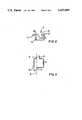
- FIG. 2 is a perspective view of the latch member of the assembly of FIG. 1;
- FIG. 3 is a plan thereof.
- a latch assembly comprises a first member 1 which, in the present case is a strut attached to the frame of a folding rear seat cushion for a motor vehicle, and a catch 2 riveted on to a second member 3, which, in the present case, is the floor panel of a motor vehicle body.
- the rear seat cushion is hinged to the vehicle body along its front edge (not shown) so that the seat cushion can be raised from the position shown in the drawings, as indicated in the arrow 4.
- the strut 1 comprises a top surface 5 and two side flanges 6, which define a space of generally rectangular cross-section within the strut 1.
- the front of the strut 1 defines a rectangular aperture 8.
- a latch member 9 in the form of a bent rod of spring wire is mounted in the strut 1.
- the latch member 9 comprises a loop of wire the two free ends 10, 11 of which are parallel to each other and located in similarly sized apertures 12, 13 in one flange 6 of the strut 1.
- the wire is bent to form two lobes 14, 15 of generally rectangular shape each of which lies approximately in a plane which extends radially from a common axis 16 (FIG. 2) and which is parallel to the axis of the free ends of the wire loop 9.
- the two lobes are of different sizes and are interconnected by a bridging portion 17 extending approximately along the common axis 16.
- the two planes in which the lobes 14, 15 lie are inclined to each other at an acute angle of about 75°, and the two lobes are received snugly within the rectangular cross-sectional area defined between the rear surface 5 and flanges 6 of the strut 1.
- a strap 20 passes around one of the lobes 15 through the aperture 8 to lie on the upper surface of the cushion.
- a spring clip 18 mounted in the strut 1 supports the latch member 9 by the bridging portion 17.
- the latch member 9 is therefore pivotable between a normal position, illustrated in solid lines in FIG. 1 and a releasing position, by rotation of the lobes 14, 15 about the axis 16. Such rotation distorts the wire loop and therefore generates a restoring force in the loop which biases the lobes towards their normal position.
- one of the lobes 14 can engage the catch 2 and therefore holds the strut 1 against the floor panel 3.
- the latch member 9 can be released by pulling the strap 20 to move the lobe 15 upwardly into the releasing position.
- the embodiment of the invention described above therefore provides a very simple and effective latch mechanism, requiring a minimum number of working parts and forming operations.
Landscapes
- Engineering & Computer Science (AREA)
- Mechanical Engineering (AREA)
- Aviation & Aerospace Engineering (AREA)
- Transportation (AREA)
- Seats For Vehicles (AREA)
Applications Claiming Priority (2)
| Application Number | Priority Date | Filing Date | Title |
|---|---|---|---|
| GB8007487A GB2071749A (en) | 1980-03-05 | 1980-03-05 | Latch assembly |
| GB8007487 | 1980-03-05 |
Publications (1)
| Publication Number | Publication Date |
|---|---|
| US4455049A true US4455049A (en) | 1984-06-19 |
Family
ID=10511889
Family Applications (1)
| Application Number | Title | Priority Date | Filing Date |
|---|---|---|---|
| US06/314,091 Expired - Fee Related US4455049A (en) | 1980-03-05 | 1981-03-04 | Latch assembly |
Country Status (7)
| Country | Link |
|---|---|
| US (1) | US4455049A (de) |
| EP (1) | EP0047269B1 (de) |
| JP (1) | JPS57917A (de) |
| DE (1) | DE3165622D1 (de) |
| ES (1) | ES264799Y (de) |
| GB (1) | GB2071749A (de) |
| WO (1) | WO1981002549A1 (de) |
Cited By (9)
| Publication number | Priority date | Publication date | Assignee | Title |
|---|---|---|---|---|
| FR2817205A1 (fr) * | 2000-11-28 | 2002-05-31 | Peugeot Citroen Automobiles Sa | Dispositif de commande d'articulation d'un dossier de siege rabattable |
| US20110115274A1 (en) * | 2009-11-13 | 2011-05-19 | Toyota Motor Engineering & Manufacturing North America, Inc. | Release strap for a recliner mechanism of an automotive vehicle seat assembly |
| US20110127822A1 (en) * | 2009-11-30 | 2011-06-02 | Toyota Motor Engineering & Manufacturing North America, Inc. | Seat assembly having rear actuated egress mechanism |
| US20120212013A1 (en) * | 2008-02-04 | 2012-08-23 | Polaris Industries Inc. | Atv having arrangement for a passenger |
| US20130161993A1 (en) * | 2011-12-27 | 2013-06-27 | Toyota Boshoku Kabushiki Kaisha | Vehicle seat |
| US10525853B2 (en) * | 2018-03-06 | 2020-01-07 | Honda Motor Co., Ltd. | Apparatus for returning a stow strap to a retained access position |
| USD955952S1 (en) | 2019-07-25 | 2022-06-28 | Polaris Industries Inc. | Door for a utility vehicle |
| USD962141S1 (en) | 2019-07-26 | 2022-08-30 | Polaris Industries Inc. | Vehicle door |
| US11447040B2 (en) | 2019-07-26 | 2022-09-20 | Polaris Industries Inc. | Side-by-side vehicle |
Families Citing this family (6)
| Publication number | Priority date | Publication date | Assignee | Title |
|---|---|---|---|---|
| DE3421564A1 (de) * | 1984-06-09 | 1985-12-12 | Adam Opel AG, 6090 Rüsselsheim | Verriegelungsvorrichtung fuer das sitzteil eines hintersitzes |
| DE3532374A1 (de) * | 1985-09-11 | 1987-03-19 | Daimler Benz Ag | Verriegelungsvorrichtung fuer ein abgeklapptes sitzkissen |
| GB9215812D0 (en) * | 1992-07-24 | 1992-09-09 | Nissan Europ Tech Centre | Seat assembly latch mechanism |
| FR2720985B1 (fr) * | 1994-06-14 | 1996-09-06 | Faure France Bertrand | Système de verrouillage d'un élément mobile d'un siège de véhicule automobile. |
| JP4082148B2 (ja) | 2002-09-19 | 2008-04-30 | トヨタ紡織株式会社 | 車両用シートの脱着装置 |
| DE10321296A1 (de) * | 2003-05-13 | 2004-07-15 | Daimlerchrysler Ag | Zuglasche |
Citations (8)
| Publication number | Priority date | Publication date | Assignee | Title |
|---|---|---|---|---|
| US611235A (en) * | 1898-09-27 | Supplemental blind-latch | ||
| US1380263A (en) * | 1919-11-15 | 1921-05-31 | George W Stein | Window-lock |
| US1480956A (en) * | 1922-05-09 | 1924-01-15 | Vern F Robinson | Latch for gates |
| US1573368A (en) * | 1924-09-26 | 1926-02-16 | Lawrence O Flynn | Combined door check and fastener |
| US3210776A (en) * | 1964-04-15 | 1965-10-12 | Darwin S Cox | Self adjusting, releasable appliance mounting structure |
| US3719379A (en) * | 1969-09-29 | 1973-03-06 | Daimler Benz Ag | Backrest locking mechanism of vehicle seats |
| US3915493A (en) * | 1974-11-21 | 1975-10-28 | Gen Motors Corp | Seat cushion retainer device |
| US4057271A (en) * | 1975-02-07 | 1977-11-08 | Regie Nationale Des Usines Renault | Automobile bonnet ejection and retaining device |
Family Cites Families (3)
| Publication number | Priority date | Publication date | Assignee | Title |
|---|---|---|---|---|
| US1776717A (en) * | 1929-01-29 | 1930-09-23 | George P Bebber | Closure fastener |
| GB495362A (en) * | 1937-11-10 | 1938-11-11 | Accessoire Precision | Device applicable for maintaining a movable member against a fixed member and in particular for hooking automobile bonnets |
| DE1801108A1 (de) * | 1968-10-04 | 1970-04-16 | Daimler Benz Ag | Vorrichtung zur loesbaren Befestigung der Fondlehne von Personenkraftwagen |
-
1980
- 1980-03-05 GB GB8007487A patent/GB2071749A/en not_active Withdrawn
-
1981
- 1981-03-04 ES ES1981264799U patent/ES264799Y/es not_active Expired
- 1981-03-04 EP EP81900558A patent/EP0047269B1/de not_active Expired
- 1981-03-04 JP JP3107681A patent/JPS57917A/ja active Pending
- 1981-03-04 US US06/314,091 patent/US4455049A/en not_active Expired - Fee Related
- 1981-03-04 WO PCT/GB1981/000037 patent/WO1981002549A1/en active IP Right Grant
- 1981-03-04 DE DE8181900558T patent/DE3165622D1/de not_active Expired
Patent Citations (8)
| Publication number | Priority date | Publication date | Assignee | Title |
|---|---|---|---|---|
| US611235A (en) * | 1898-09-27 | Supplemental blind-latch | ||
| US1380263A (en) * | 1919-11-15 | 1921-05-31 | George W Stein | Window-lock |
| US1480956A (en) * | 1922-05-09 | 1924-01-15 | Vern F Robinson | Latch for gates |
| US1573368A (en) * | 1924-09-26 | 1926-02-16 | Lawrence O Flynn | Combined door check and fastener |
| US3210776A (en) * | 1964-04-15 | 1965-10-12 | Darwin S Cox | Self adjusting, releasable appliance mounting structure |
| US3719379A (en) * | 1969-09-29 | 1973-03-06 | Daimler Benz Ag | Backrest locking mechanism of vehicle seats |
| US3915493A (en) * | 1974-11-21 | 1975-10-28 | Gen Motors Corp | Seat cushion retainer device |
| US4057271A (en) * | 1975-02-07 | 1977-11-08 | Regie Nationale Des Usines Renault | Automobile bonnet ejection and retaining device |
Cited By (14)
| Publication number | Priority date | Publication date | Assignee | Title |
|---|---|---|---|---|
| FR2817205A1 (fr) * | 2000-11-28 | 2002-05-31 | Peugeot Citroen Automobiles Sa | Dispositif de commande d'articulation d'un dossier de siege rabattable |
| US8905435B2 (en) * | 2008-02-04 | 2014-12-09 | Polaris Industries Inc. | ATV having arrangement for a passenger |
| US9663172B2 (en) | 2008-02-04 | 2017-05-30 | Polaris Industries Inc. | ATV having arrangement for a passenger |
| US20120212013A1 (en) * | 2008-02-04 | 2012-08-23 | Polaris Industries Inc. | Atv having arrangement for a passenger |
| US20110115274A1 (en) * | 2009-11-13 | 2011-05-19 | Toyota Motor Engineering & Manufacturing North America, Inc. | Release strap for a recliner mechanism of an automotive vehicle seat assembly |
| US8191968B2 (en) * | 2009-11-13 | 2012-06-05 | Toyota Motor Engineering & Manufacturing North America, Inc. | Release strap for a recliner mechanism of an automotive vehicle seat assembly |
| US8182041B2 (en) * | 2009-11-30 | 2012-05-22 | Toyota Motor Engineering & Manufacturing North America, Inc. | Seat assembly having rear actuated egress mechanism |
| US20110127822A1 (en) * | 2009-11-30 | 2011-06-02 | Toyota Motor Engineering & Manufacturing North America, Inc. | Seat assembly having rear actuated egress mechanism |
| US8888186B2 (en) * | 2011-12-27 | 2014-11-18 | Toyota Boshoku Kabushiki Kaisha | Vehicle seat |
| US20130161993A1 (en) * | 2011-12-27 | 2013-06-27 | Toyota Boshoku Kabushiki Kaisha | Vehicle seat |
| US10525853B2 (en) * | 2018-03-06 | 2020-01-07 | Honda Motor Co., Ltd. | Apparatus for returning a stow strap to a retained access position |
| USD955952S1 (en) | 2019-07-25 | 2022-06-28 | Polaris Industries Inc. | Door for a utility vehicle |
| USD962141S1 (en) | 2019-07-26 | 2022-08-30 | Polaris Industries Inc. | Vehicle door |
| US11447040B2 (en) | 2019-07-26 | 2022-09-20 | Polaris Industries Inc. | Side-by-side vehicle |
Also Published As
| Publication number | Publication date |
|---|---|
| EP0047269B1 (de) | 1984-08-22 |
| ES264799Y (es) | 1983-12-01 |
| ES264799U (es) | 1983-06-01 |
| GB2071749A (en) | 1981-09-23 |
| EP0047269A1 (de) | 1982-03-17 |
| WO1981002549A1 (en) | 1981-09-17 |
| JPS57917A (en) | 1982-01-06 |
| DE3165622D1 (en) | 1984-09-27 |
Similar Documents
| Publication | Publication Date | Title |
|---|---|---|
| US4455049A (en) | Latch assembly | |
| US4387926A (en) | Seat positioner | |
| US5828750A (en) | Positive holding rack | |
| US4646400A (en) | Buckle apparatus | |
| US5466048A (en) | Backrest release mechanism | |
| US5938051A (en) | Stacking column for storing articles | |
| DE60212622T2 (de) | Behälterzusammenbau | |
| US6352164B1 (en) | Storage rack having locking beam-to-column connection | |
| US4428447A (en) | Vehicle front end structure | |
| US5183314A (en) | Concealed mechanism for detachably mounting a vehicle seat | |
| GB2028592A (en) | Car antennae | |
| US4205879A (en) | Insertable armrest for a vehicle seat | |
| US4743050A (en) | Shopping cart clipboard | |
| EP1251043A1 (de) | Baueinheit aus Gassackmodul und Fahrzeuglenkrad | |
| EP0983914A2 (de) | Mittel zur Befestigung eines Gasgenerators in einem Airbagmodul | |
| US3003800A (en) | Automotive hood safety latch | |
| US4820093A (en) | Retractable rope hook arrangement for vehicle | |
| US4919486A (en) | Vehicular seat | |
| US2796268A (en) | Folding table leg bracket | |
| CA1153298A (en) | Latch assembly | |
| US4919155A (en) | Hair clip | |
| US4190226A (en) | Vehicle seat slides | |
| AU7252987A (en) | Device for locking a unit load | |
| US4781410A (en) | Removable roof assembly with improved wind deflector | |
| DE3610361C2 (de) | Befestigung für Scheinwerfer in einer Öffnung der Karosserie eines Kraftfahrzeugs |
Legal Events
| Date | Code | Title | Description |
|---|---|---|---|
| AS | Assignment |
Owner name: FORD MOTOR COMPANY, DEARBORN, MI., A DE CORP. Free format text: ASSIGNMENT OF ASSIGNORS INTEREST.;ASSIGNOR:MARTIN, BRIAN D.;REEL/FRAME:004179/0940 Effective date: 19810409 |
|
| REMI | Maintenance fee reminder mailed | ||
| LAPS | Lapse for failure to pay maintenance fees | ||
| STCH | Information on status: patent discontinuation |
Free format text: PATENT EXPIRED DUE TO NONPAYMENT OF MAINTENANCE FEES UNDER 37 CFR 1.362 |
|
| FP | Lapsed due to failure to pay maintenance fee |
Effective date: 19880619 |