US4429265A - Motor driven window winding mechanisms - Google Patents
Motor driven window winding mechanisms Download PDFInfo
- Publication number
- US4429265A US4429265A US06/216,707 US21670780A US4429265A US 4429265 A US4429265 A US 4429265A US 21670780 A US21670780 A US 21670780A US 4429265 A US4429265 A US 4429265A
- Authority
- US
- United States
- Prior art keywords
- winding mechanism
- motor driven
- motor
- mechanism according
- driven winding
- Prior art date
- Legal status (The legal status is an assumption and is not a legal conclusion. Google has not performed a legal analysis and makes no representation as to the accuracy of the status listed.)
- Expired - Fee Related
Links
Images


Classifications
-
- E—FIXED CONSTRUCTIONS
- E05—LOCKS; KEYS; WINDOW OR DOOR FITTINGS; SAFES
- E05F—DEVICES FOR MOVING WINGS INTO OPEN OR CLOSED POSITION; CHECKS FOR WINGS; WING FITTINGS NOT OTHERWISE PROVIDED FOR, CONCERNED WITH THE FUNCTIONING OF THE WING
- E05F15/00—Power-operated mechanisms for wings
- E05F15/40—Safety devices, e.g. detection of obstructions or end positions
- E05F15/41—Detection by monitoring transmitted force or torque; Safety couplings with activation dependent upon torque or force, e.g. slip couplings
-
- E—FIXED CONSTRUCTIONS
- E05—LOCKS; KEYS; WINDOW OR DOOR FITTINGS; SAFES
- E05Y—INDEXING SCHEME RELATING TO HINGES OR OTHER SUSPENSION DEVICES FOR DOORS, WINDOWS OR WINGS AND DEVICES FOR MOVING WINGS INTO OPEN OR CLOSED POSITION, CHECKS FOR WINGS AND WING FITTINGS NOT OTHERWISE PROVIDED FOR, CONCERNED WITH THE FUNCTIONING OF THE WING
- E05Y2201/00—Constructional elements; Accessories therefore
- E05Y2201/40—Motors; Magnets; Springs; Weights; Accessories therefore
- E05Y2201/47—Springs; Spring tensioners
- E05Y2201/488—Traction springs
-
- E—FIXED CONSTRUCTIONS
- E05—LOCKS; KEYS; WINDOW OR DOOR FITTINGS; SAFES
- E05Y—INDEXING SCHEME RELATING TO HINGES OR OTHER SUSPENSION DEVICES FOR DOORS, WINDOWS OR WINGS AND DEVICES FOR MOVING WINGS INTO OPEN OR CLOSED POSITION, CHECKS FOR WINGS AND WING FITTINGS NOT OTHERWISE PROVIDED FOR, CONCERNED WITH THE FUNCTIONING OF THE WING
- E05Y2400/00—Electronic control; Power supply; Power or signal transmission; User interfaces
- E05Y2400/10—Electronic control
- E05Y2400/52—Safety arrangements
- E05Y2400/53—Wing impact prevention or reduction
- E05Y2400/54—Obstruction or resistance detection
- E05Y2400/55—Obstruction or resistance detection by using load sensors
- E05Y2400/552—Switches
-
- E—FIXED CONSTRUCTIONS
- E05—LOCKS; KEYS; WINDOW OR DOOR FITTINGS; SAFES
- E05Y—INDEXING SCHEME RELATING TO HINGES OR OTHER SUSPENSION DEVICES FOR DOORS, WINDOWS OR WINGS AND DEVICES FOR MOVING WINGS INTO OPEN OR CLOSED POSITION, CHECKS FOR WINGS AND WING FITTINGS NOT OTHERWISE PROVIDED FOR, CONCERNED WITH THE FUNCTIONING OF THE WING
- E05Y2600/00—Mounting or coupling arrangements for elements provided for in this subclass
- E05Y2600/10—Adjustable or movable
- E05Y2600/11—Adjustable or movable by automatically acting means
-
- E—FIXED CONSTRUCTIONS
- E05—LOCKS; KEYS; WINDOW OR DOOR FITTINGS; SAFES
- E05Y—INDEXING SCHEME RELATING TO HINGES OR OTHER SUSPENSION DEVICES FOR DOORS, WINDOWS OR WINGS AND DEVICES FOR MOVING WINGS INTO OPEN OR CLOSED POSITION, CHECKS FOR WINGS AND WING FITTINGS NOT OTHERWISE PROVIDED FOR, CONCERNED WITH THE FUNCTIONING OF THE WING
- E05Y2900/00—Application of doors, windows, wings or fittings thereof
- E05Y2900/50—Application of doors, windows, wings or fittings thereof for vehicles
- E05Y2900/53—Application of doors, windows, wings or fittings thereof for vehicles characterised by the type of wing
- E05Y2900/55—Windows
Definitions
- This invention relates to motor driven winding mechanisms and, more particularly, to motor driven window winding mechanisms for mounting in a vehicle panel of the kind provided with an operating shaft rotatably mounted thereon and a transmission which applies movement to a window in response to rotation of the operating shaft.
- the invention is particularly concerned with motor driven window winding mechanisms of the type described in, for example, U.K. Patent Specification No. 1511861, in which a reversible electric motor is arranged to drive, through a flexible cable, a reduction gear unit that is coupled to and mounted on the operating shaft in the vehicle door whereby operation of the electric motor is effective to rotate the operating shaft and thereby raise, or lower, the vehicle window.
- the inherent mechanical resistance of the window winding transmission may be minimal in which case it would be desirable to provide means for reducing the risk of injury in the event that a person's fingers become trapped between the window and the window frame.
- a motor driven winding mechanism suitable for mounting in a vehicle door of the kind having an operating shaft mounted thereon rotation of which is effective to move a window, comprising a motor, a reduction gear unit which is adapted to be mounted on the operating shaft and which has an input that is arranged to be driven by the motor and an output that is to be operatively coupled to the operating shaft for rotating the operating shaft, and sensing means for sensing reactive torque produced in the reduction gear unit during operation and controlling operation of the motor in accordance therewith.
- the sensing means may be arranged to de-energise or, alternatively, reverse the motor upon a predetermined reactive torque being sensed thereby.
- the sensing means is arranged to sense displacement of the reduction gear unit about the axis of the operating shaft relative to the vehicle panel resulting from reactive torque produced in the reduction gear unit during operation.
- the sensing means may also include means, for example resilient means, for restraining displacement of the reduction gear unit arround the axis of the operating shaft, and be arranged to sense displacement of the reduction gear unit against the action of the restraining means.
- the sensing means may be arranged to sense displacement of the reduction gear unit in either directional sense around the axis of the operating shaft.
- the sensing means preferably includes responsive means, for example an electric switch, responsive to a predetermined displacement of the reduction gear unit.
- a member may be attached to the reduction gear unit to move with the unit in which case the sensing means may be arranged to sense pivotal displacement of that member around the axis of the operating shaft.
- the mechanism may include means for loosely coupling the member to the vehicle panel.
- This loose coupling means which preferably comprises a pin and slot arrangement, may define a stop for limiting pivotal displacement of the member in a first direction towards which the member is biassed by the resilient means.
- the sensing means is preferably arranged to respond, for example by means of an electrical switch, to a predetermined displacement of the member in a second direction to control operation of the motor in accordance therewith.
- the loose coupling again for example comprising a pin and slot arrangement, may define a rest position for the member towards which the member is biassed by the resilient means.
- the sensing means is preferably arranged to respond to a predetermined pivotal displacement of the member in either directional sense away from that rest position.
- the reduction gear unit which may include an input gear drivingly coupled to the motor through, for example a flexible drive shaft, an output gear for rotatably driving the operating shaft and a housing for the gears, is preferably adapted to be mounted on and supported solely by the operating shaft.
- FIG. 1 is a side view of a known reduction gearing of the mechanisms with its casing partially removed;
- FIG. 2 is a sectional view of the line II--II of FIG. 1;
- FIG. 3 is a fragmentary sectional view of the known reduction gearing showing means for coupling the reduction gearing to conventional operating shaft for a vehicle window;
- FIG. 4 is a perspective view of a part of a vehicle door showing components of one form of the mechanism installed therein;
- FIGS. 5 and 6 are enlarged sectional views of a part of the mechanism of FIG. 4 showing alternative arrangements.
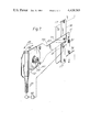
- FIG. 7 is a perspective view of a part of a vehicle door showing components of another form of the mechanism installed therein.
- the motor driven window winding mechanisms are for use with an existing conventional manually-operated window winding mechanism of a motor vehicle having an operating shaft and a transmission which applies movement to a motor vehicle window in response to rotation of the operating shaft.
- the motor driven window winding mechanisms include a reversible electric motor which drives the operating shaft for the window through a reduction gearing unit.
- This reduction gearing unit is mounted on and supported solely by the operating shaft and comprises a worm gear, a worm to drive the worm gear and a coupling device which couples the worm gear to the operating shaft.
- the worm gear is connected to one end of a flexible drive cable whose other end is connected to the output shaft of the motor which is disposed in the door at a location remote from the reduction gearing. Operation of the motor is controlled by electric switches which are mounted on, for example, the dashboard of the vehicle or the appropriate vehicle door and which are operable to control the direction and extent of rotation of the motor output shaft and thereby enable the respective vehicle window to be appropriately positioned.
- the reduction gearing includes a worm 10 and a worm gear 11 mounted in meshing engagement in a casing 12.
- This casing 12 is in two parts 13 and 14, each part being pressed from mild steel sheet to provide a circular recess 15 to house the worm gear 11 and two half-cylindrical sockets 16 which are intersected by the recess 15.
- the resulting flanges 17 around the recesses 15 abut one another and are secured together by, for example, rivets.
- the worm 10 is rotatably mounted in the half-cylindrical sockets in meshing engagement with the worm gear 11.
- the shaft of the worm 10 is of reduced diameter at one end and supported in a moulded nylon bearing 18 clamped between the two parts 13 and 14 of the casing.
- the other end of the worm shaft is also of reduced diameter and is mounted in a bearing formed in a moulded nylon ferrule 20.
- the worm gear 11 is moulded of plastics and is rotatably mounted in a bearing provided by the casing 12.
- the two parts 13 and 14 have respective circular apertures 21 and 22 therein aligned with the rotational axis of the gear 11, the edge of the part 13 bounding the aperture 21 being turned outwardly to provide a continuous annular bearing surface 23 for the gear 11.
- An axially-extending projection 24 of annular cross-section and providing a continuous annular surface is moulded integrally with the gear 11 on the side thereof adjacent the bearing surface 23 and this projection extends through the bearing aperture 21 with the outer circumferential surface of the projection 24 engaging the bearing surface 23.
- Annular projections 25, centred on the rotational axis of the gear 11, are provided on the sides of the gear to limit the extent of sideways movement of that gear in the casing 12.
- An aperture 26 of hexagonal shape is moulded in the other side of the gear 11 and this aperture houses a plate-like part 29 (FIG. 3) of metal having an hexagonal outer edge which engages with the aperture 26 so that the part 29 is driven by the gear 11.
- the part 29 has a central, square aperture to receive the operating shaft, the inner portion of the part 29 being shaped to define a short sleeve of rectangular cross-section that extends axially of the operating shaft and is spaced therefrom.
- the part 29 may be secured to the drive gear 11 by screws (not shown).
- the device for coupling the part 29 to the operating shaft is constituted by a moulded insert 30 of glass-filled nylon having a sleeve portion of square cross-section which fits snugly in the part 29.
- the insert 30 has a central aperture to receive the operating shaft so that the reduction gearing is supported by the operating shaft and mounted thereon.
- the operating shaft (50) When it is required to mount the reduction gearing on the shaft, the operating shaft (50) is inserted through the aperture in the part 29, and the insert 30 is then inserted into the space between the part 29 and the shaft. Rotation of the operating shaft 50, as shown in FIG. 3, serves to raise and lower the vehicle window, referenced at 40, through mechanical transmission 41.
- the end of the operating shaft on which the reduction gearing is mounted may be of a number of different cross-section shapes, and in these circumstances, a similar number of different inserts 30 are provided, the inserts having central apertures to cooperate with respective ones of the shafts.
- the insert 30 is removed to disengage the reduction gearing from the operating shaft and permit emergency manual operations of the operating shaft.
- the reduction gearing in each case is shown mounted on, and supported by the operating shaft, 50, covered by the insert 30, in a vehicle door panel.
- the output from the reversible electric motor (shown schematically) is connected to the reduction gearing through the flexible drive shaft 31 which comprises a plastics covered outer sleeve and an inner drive member of helically-wound metal strip.
- the reversible electric motor which is mounted on the door structure remote from the operating shaft, is a conventional d.c.
- electric motor with its associated control switch unit as schematically represented at 51 being electrically connected between the ignition switch of the vehicle and the motor windings and being selectable to control the direction of current flow through the windings and hence the direction of rotation of the motor and the direction of movement of the respective window.
- a torque arm 52 is mounted on the casing 12 of the reduction gearing and cooperates with a fixed part of the door panel through an intermediate member 55 to prevent substantial rotation of the reduction gearing around the axis of the operating shaft 50 upon operation of the electric motor.
- the torque arm comprises an elongate metal plate which is screwed at is one end onto the casing 12 of the reduction gearing so as to be immovable with respect thereto, and which has, as shown more clearly in FIG. 5, a straight slot 53 therein adjacent its other end through which projects a pin 54 carried by the member 55.
- the member 55 extends across an aperture 56 in the door panel 58 and is mounted on the door panel 58 by means of a bolt 57 through its end remote from the torque arm 52 whereby it is capable of pivotal movement around the bolts 57.
- the pin 54 is mounted on the member 55 such that it extends along a line substantially parallel to the axis of the operating shaft and at right angles to the plane of the torque arm 52.
- the longitudinal dimension of the slots 53 which as shown in FIG.
- the reduction gear unit be mounted on the operating shaft in a plane substantially at right angles to the axis of the operating shaft, with the axis of the bore of the insert 30 being aligned with that of the operating shaft, and that any loading on the reduction gearing tending to pull it away from this desired configuration, (as could occur if, for example, a short metal strap were simply screwed between one edge of the casing 12 and the door panel to prevent rotation of the reduction gearing about the axis of the operating shaft and if that strap were not suitably shaped to take into account the displacement of the plane of the reduction gearing from that of the door panel), is eliminated or at least reduced.
- a helical spring 60 is connected between the member 55, at a point intermediate the pin 54 and the bolt 57, and the casing 12 of the reduction gearing, and is arranged to urge the member 55 anticlockwise in FIG. 4 such that, under normal circumstances, the torque arm 52 is biassed clockwise around the operating shaft 50 through cooperation of the pin 54 with the sloping slot 53 whereby the pin 54 bears against the lower end of the slot 53, as shown in FIG. 5.
- a micro-switch 61 is mounted on the torque arm 52 adjacent the member 55 with one edge of the member 55 bearing against the operating element 62 of the microswitch 61.
- the microswitch 61 is arranged with respect to the member 55 such that when the torque arm 52 is in the position shown in FIG. 4, that is, with the pin 54 in engagement with the lower end of the slot 53, the micro-switch is in its closed state, and when the torque arm 52 pivots anti-clockwise around the axis of the operating shaft through a predetermined displacement against the action of the helical spring 60, the aforementioned edge of the member 55 is moved away from the operating element of the micro-switch so as to switch it to its open state.
- the micro-switch 61 is wired into the electrical circuit which supplies current to the reversible motor to raise the window, and is operable to open and close that circuit when in its open and closed states respectively.
- the pin and slot arrangement serves to allow some backlash in the window winding mechanism.
- the electric motor is de-energised by a limit switch (not shown) connected in the electrical circuit supplying current to the motor, the limit switch being arranged to be mechanically actuated by the window to open that circuit upon the window attaining its lowermost position.
- the electric motor is energised in the reverse direction so that the worm 10, worm gear 11, insert 30 and the operating shaft are driven in the opposite sense to that for lowering the window.
- the end of the spring 60 remote from the casing 12 may be attached to a suitably chosen point on the member 55 intermediate the pin 54 and the bolt 57.
- the micro-switch 61 senses the abnormally high reactive torque in the reduction gearing and responds to a predetermined value thereof to de-energise the electric motor.
- means such as a diode may be included in the power-supply circuit to the motor within the control switch unit 51 so as to enable the motor to be reversed to reset the micro-switch 61.
- the torque arm 52 may return to its initial position under the action of the spring 60, and the micro-switch 61 reset accordingly, upon momentary removal of the excessive torque by de-energisation of the motor as described so that reversal is unnecessary.
- the arrangement in addition to sensing and responding to an abnormally high reactive torque produced in the reduction gearing as a result of an object bearing against the window, the arrangement also serves, firstly, to act as a limit switch to de-energise the electric motor once the window has reached its uppermost position by sensing and responding to the increase in reactive torque produced as a result of the increase in load on the window winding transmission caused by abutment of the window against the window frame, and, secondly, by sensing and responding to a predetermined increase in reactive torque set up in the reduction gearing caused by any abnormalities in the window winding transmission itself.
- the elongate torque arm 52 serves to magnify any rotational displacement of the reduction gearing about the axis of the operating shaft, and that by appropriately varying the length of the torque arm 52, the position of the slot 53 and the pin 54 along the member 55, the length of the slot 53, the positions of the micro-switch 61 along the arm 52 and the spring 60 along the member 55, and the tension of the spring 60, the mechanism may be adapted to suit different installations and accommodate their respective requirements.
- the arrangement may be adapted to sense abnormally high reactive torque produced in the reduction gearing during both lowering and raising operations of the window by using a modified shape of slot in the torque arm 52 as shown in FIG. 6.
- the modified slot, 63 is generally V-shaped having an upper portion corresponding substantially as regards both its slope and length with the slot 53 shown in FIG. 5 and a lower portion which slopes in the opposite direction such that the slot 63 points towards the operating shaft with the apex of the V disposed closer to the reduction gearing than the upper and lower ends of the slot 63.
- the spring 60 acts on the member 55 such that the pin 54 is urged towards and rests in the apex of the V-shape slot, as is shown in FIG. 6.
- the pin 54 slides along the upper portion of the slot 63 in an identical manner with that of the arrangement described with reference to FIGS. 4 and 5 such that the member 55 is moved away from the operating element 62 of the micro-switch 61 thereby actuating the switch 61 to de-energise the electric motor.
- the torque arm 52 may be returned to its initial position under the action of the spring 60 so that the micro-switch is reset accordingly.
- means in the control switch unit 51 may comprise a resistance connected across the micro-switch which allows just sufficient motor current for it to reverse and thereby effect resetting of the micro-switch 61.
- the micro-switch 61 may be arranged in the power supply circuit to the motor such that the actuation thereof in the aforementioned manner serves to operate the control switch unit 51 to cause energization of the motor in the reverse sense.
- FIG. 7 A modified form of the motor driven window winding mechanism of FIG. 4 will now be described with reference to FIG. 7. It will be appreciated that the mechanism is generally similar to the previously described embodiment and that the foregoing description is applicable to this mechanism so far as the same components or similar counterparts are concerned. The following description will concern itself primarily therefore with the components of the mechanism which differ from those described previously.
- a torque arm 72 comprising an elongate metal plate is mounted at its one end on the casing 12 of the reduction gearing and cooperates with a fixed part on the door panel to prevent substantial rotation of the reduction gearing around the axis of the operating shaft upon operation of the electric motor.
- the torque arm 72 has a vertical slot 73 adjacent its other end through which projects a pin 74 carried by a bracket 75 that is secured across an aperture 76 in the door panel 78 by means of screws 77.
- the pin 74 extends substantially parallel to the axis of the operating shaft and ar right angles to the plane of the torque arm 72.
- the slot 73 and the pin 74 are arranged such that the torque arm 72, together with the reduction gearing, is capable of pivoting through a small angle around the axis of the operating shaft 50, which is limited be engagement between the pin 74 and the ends of the slot 73.
- this pin and slot arrangement facilitates installation of the mechanism in a vehicle door since the reduction gearing is allowed to find its own position with respect to the operating shaft 50 when mounted thereon.
- a helical spring 80 connected between the end of the torque arm 72 and the door structure is arranged to bias the arm 72 downwardly in FIG. 7 such that the upper end of the slot 73 bears against the pin 74.
- a micro-switch 81 is mounted on the bracket 75 beneath the torque arm 72 with the torque arm 72 bearing against the operating element 82 of the micro-switch 81.
- the micro-switch 81 is arranged with respect to the torque arm 72 such that when the torque arm 72 is in the position shown in FIG. 7, that is, with the pin 74 in engagement with the upper end of the slot 73, the micro-switch is in its closed state, and when the torque arm 72 pivots anti-clockwise around the axis of the operating shaft, as indicated by the arrow 84 a predetermined displacement of the torque arm 72 operates the micro-switch to switch it to its open state.
- the micro-switch 81 is wired into the control switch unit 51 which supplies current to the reversible motor to raise the window, and is operable to open and close that circuit when in its open and closed states respectively.
- the pin and slot arrangement serves to allow some backlash in the window winding mechanism.
- the electric motor is de-energised by a limit switch upon the window attaining its lowermost position.
- the electric motor is energised in the reverse direction so that the worm 10, worm gear 11, insert 30 and the operating shaft are driven in the opposite sense.
- the reactive torque produced in the reduction gearing is this time in the opposite sense and tends to rotate the reduction gearing in an anti-clockwise direction in FIG. 7 around the axis of the operating shaft.
- any additional loading should be applied to the window winding transmission, for example, as the result of an object such as a hand bearing on the window, the mechanical resistance of the window winding transmission is increased with a corresponding increase in the resultant reactive torque set up in the reduction gearing and the tendency for the arm 72 to rotate.
- a predetermined value determined to a certain extent by the location of the pin and slot arrangement and the spring along the arm 72 and the spring tension, the tension in the spring is overcome and the torque arm pivots anti-clockwise as indicated by the arrow 85 in FIG. 7.
- the torque arm 72 moves away from the operating element 82 of the micro-switch 81 and, upon a predetermined pivotal displacement of the torque arm 72 being attained, the micro-switch 81 is actuated to change to its open state, thereby interrupting supply of electrical power to the motor through the control switch unit 51.
- micro-switch 81 senses the abnormally high reactive torque in the reduction gearing and responds to de-energise the electric motor.
- the arrangement can also serve both to act as a limit switch to de-energise the electric motor once the window has reached its uppermost position, and to de-energise the motor in response to increase in reactive torque set up in the reduction gearing caused by any abnormalities in the window winding transmission itself.
- the micro-switch 81 may be connected to the control switch unit 51 in the motor power supply circuit such that actuation thereof in the aforementioned manner causes the motor to operate in the reverse sense.
- the torque arm 72 serves to magnify any rotational displacement of the reduction gearing about the axis of the operating shaft, and that by appropriately varying the length of the torque arm 72, the positions of the slot 73, micro-switch 81 and the spring 80 along the arm 72, and the tension of the spring 80, the mechanism may be adapted to suit different installations and accommodates their respective requirements.
Landscapes
- Power-Operated Mechanisms For Wings (AREA)
- Window Of Vehicle (AREA)
Applications Claiming Priority (4)
| Application Number | Priority Date | Filing Date | Title |
|---|---|---|---|
| GB7943141 | 1979-12-14 | ||
| GB7943141 | 1979-12-14 | ||
| GB8024347 | 1980-07-24 | ||
| GB8024347 | 1980-07-24 |
Publications (1)
| Publication Number | Publication Date |
|---|---|
| US4429265A true US4429265A (en) | 1984-01-31 |
Family
ID=26273876
Family Applications (1)
| Application Number | Title | Priority Date | Filing Date |
|---|---|---|---|
| US06/216,707 Expired - Fee Related US4429265A (en) | 1979-12-14 | 1980-12-15 | Motor driven window winding mechanisms |
Country Status (2)
| Country | Link |
|---|---|
| US (1) | US4429265A (de) |
| DE (1) | DE3046453A1 (de) |
Cited By (5)
| Publication number | Priority date | Publication date | Assignee | Title |
|---|---|---|---|---|
| US5300867A (en) * | 1991-06-25 | 1994-04-05 | V. Kann Rasmussen Industri A/S | Electric drive arrangement for a cord winding and dewinding winch |
| US6125583A (en) * | 1997-08-13 | 2000-10-03 | Atoma International Inc. | Power sliding mini-van door |
| US6215265B1 (en) * | 1994-11-14 | 2001-04-10 | Elero Antriebs- Und Sonnenschutz-Technik Gmbh | System and method for controlling activating actuator motors for various mechanisms, such as roller shutters, awnings and movies screens |
| EP1229201A1 (de) * | 2001-02-05 | 2002-08-07 | Meritor Light Vehicle Systems-France | Aktivierungseinrichtung für ein funktionelles Gerät eines Kraftfahrzeuges mit Sicherheitsvorrichtung |
| US20170234052A1 (en) * | 2015-05-15 | 2017-08-17 | Ford Global Technologies, Llc | Ice Breaking Strategy For Vehicle Side Windows |
Families Citing this family (1)
| Publication number | Priority date | Publication date | Assignee | Title |
|---|---|---|---|---|
| DE4336759C1 (de) * | 1993-10-28 | 1994-07-28 | Daimler Benz Ag | Einklemmsicherung für hilfskraftbetätigte Schiebeflügel von Fahrzeugen |
-
1980
- 1980-12-10 DE DE19803046453 patent/DE3046453A1/de not_active Withdrawn
- 1980-12-15 US US06/216,707 patent/US4429265A/en not_active Expired - Fee Related
Cited By (9)
| Publication number | Priority date | Publication date | Assignee | Title |
|---|---|---|---|---|
| US5300867A (en) * | 1991-06-25 | 1994-04-05 | V. Kann Rasmussen Industri A/S | Electric drive arrangement for a cord winding and dewinding winch |
| US6215265B1 (en) * | 1994-11-14 | 2001-04-10 | Elero Antriebs- Und Sonnenschutz-Technik Gmbh | System and method for controlling activating actuator motors for various mechanisms, such as roller shutters, awnings and movies screens |
| US6125583A (en) * | 1997-08-13 | 2000-10-03 | Atoma International Inc. | Power sliding mini-van door |
| US6341448B1 (en) | 1997-08-13 | 2002-01-29 | Atoma International Corp. | Cinching latch |
| EP1229201A1 (de) * | 2001-02-05 | 2002-08-07 | Meritor Light Vehicle Systems-France | Aktivierungseinrichtung für ein funktionelles Gerät eines Kraftfahrzeuges mit Sicherheitsvorrichtung |
| FR2820557A1 (fr) * | 2001-02-05 | 2002-08-09 | Meritor Light Vehicle Sys Ltd | Dispositif d'activation d'un organe fonctionnel d'equipement de vehicule automobile dote d'un dispositif de securite |
| US6580240B2 (en) | 2001-02-05 | 2003-06-17 | Meritor Light Vehicle Systems-France | Activation device for a functional component of motor vehicle equipment equipped with a safety device |
| US20170234052A1 (en) * | 2015-05-15 | 2017-08-17 | Ford Global Technologies, Llc | Ice Breaking Strategy For Vehicle Side Windows |
| US10047554B2 (en) * | 2015-05-15 | 2018-08-14 | Ford Global Technologies, Llc | Ice breaking strategy for vehicle side windows |
Also Published As
| Publication number | Publication date |
|---|---|
| DE3046453A1 (de) | 1981-08-27 |
Similar Documents
| Publication | Publication Date | Title |
|---|---|---|
| US4628636A (en) | Garage door operator mechanism | |
| EP0495641B1 (de) | Elektronische Pedale mit verbesserter Rückstellfeder | |
| US4858481A (en) | Position controlled linear actuator | |
| US6215265B1 (en) | System and method for controlling activating actuator motors for various mechanisms, such as roller shutters, awnings and movies screens | |
| KR900010179A (ko) | 창 개폐장치 | |
| US4712441A (en) | Position controlled linear actuator | |
| EP1154912B1 (de) | Trittbrett als selbstständig ausfahrbares modul | |
| US4854193A (en) | Key interlock system for automatic floor mounted transmission shifter | |
| EP0881124A2 (de) | Betätigungsmechanismus für einen Rückblickspiegel | |
| US4429265A (en) | Motor driven window winding mechanisms | |
| US5299678A (en) | Limit switch mechanism for garage door opener | |
| EP1047577A1 (de) | Angetriebenes trittbett als modul | |
| PL174627B1 (pl) | Napęd drzwi obrotowych | |
| US4817912A (en) | Bi-metal operator for smoke, fire and air control damper | |
| US4187734A (en) | Electric regulating device | |
| CA1182091A (en) | Drive device for passive vehicle occupant restraint belt system | |
| US3785089A (en) | Door operator | |
| JPS61233183A (ja) | 自動車ドアロツク用調節装置 | |
| DE19706209B4 (de) | Vorrichtung zur Steuerung, insbesondere Endabschaltung einer motorischen Antriebsvorrichtung einer Wickelwelle eines Rolladens, Garagentors o. dgl. | |
| US3042357A (en) | Motor operated valve | |
| US11686351B2 (en) | Clutch assembly | |
| CH664808A5 (de) | Regelventil fuer heizkoerper. | |
| GB2066348A (en) | A motor driven window winding mechanism | |
| EP1213185B1 (de) | Einziehbare Leiter | |
| USRE34287E (en) | Window operator |
Legal Events
| Date | Code | Title | Description |
|---|---|---|---|
| AS | Assignment |
Owner name: SMITHS INDUSTRIES PUBLIC LIMITED COMPANY, 765 FINC Free format text: ASSIGNMENT OF ASSIGNORS INTEREST.;ASSIGNOR:BARNARD, DOMINIC P. E.;REEL/FRAME:004186/0681 Effective date: 19831021 |
|
| MAFP | Maintenance fee payment |
Free format text: PAYMENT OF MAINTENANCE FEE, 4TH YEAR, PL 96-517 (ORIGINAL EVENT CODE: M170); ENTITY STATUS OF PATENT OWNER: LARGE ENTITY Year of fee payment: 4 |
|
| AS | Assignment |
Owner name: LUCAS INDUSTRIES PUBLIC LIMITED COMPANY, GREAT KIN Free format text: ASSIGNMENT OF ASSIGNORS INTEREST.;ASSIGNOR:SMITHS INDUSTRIES PUBLIC LIMITED COMPANY, A PUBLIC LIMITED COMPANY OF UNITED KINGDOM;REEL/FRAME:004751/0409 Effective date: 19870605 |
|
| FEPP | Fee payment procedure |
Free format text: MAINTENANCE FEE REMINDER MAILED (ORIGINAL EVENT CODE: REM.); ENTITY STATUS OF PATENT OWNER: LARGE ENTITY |
|
| LAPS | Lapse for failure to pay maintenance fees | ||
| FP | Lapsed due to failure to pay maintenance fee |
Effective date: 19920131 |
|
| STCH | Information on status: patent discontinuation |
Free format text: PATENT EXPIRED DUE TO NONPAYMENT OF MAINTENANCE FEES UNDER 37 CFR 1.362 |