US4384702A - Mold insert - Google Patents
Mold insert Download PDFInfo
- Publication number
- US4384702A US4384702A US06/356,490 US35649082A US4384702A US 4384702 A US4384702 A US 4384702A US 35649082 A US35649082 A US 35649082A US 4384702 A US4384702 A US 4384702A
- Authority
- US
- United States
- Prior art keywords
- bore
- plug
- mold
- face
- indicia
- Prior art date
- Legal status (The legal status is an assumption and is not a legal conclusion. Google has not performed a legal analysis and makes no representation as to the accuracy of the status listed.)
- Expired - Lifetime
Links
- 230000006835 compression Effects 0.000 claims description 3
- 238000007906 compression Methods 0.000 claims description 3
- 239000000463 material Substances 0.000 description 4
- 230000014759 maintenance of location Effects 0.000 description 3
- 238000001746 injection moulding Methods 0.000 description 2
- 238000009413 insulation Methods 0.000 description 1
- 238000003908 quality control method Methods 0.000 description 1
- 238000007789 sealing Methods 0.000 description 1
Images

Classifications
-
- B—PERFORMING OPERATIONS; TRANSPORTING
- B29—WORKING OF PLASTICS; WORKING OF SUBSTANCES IN A PLASTIC STATE IN GENERAL
- B29C—SHAPING OR JOINING OF PLASTICS; SHAPING OF MATERIAL IN A PLASTIC STATE, NOT OTHERWISE PROVIDED FOR; AFTER-TREATMENT OF THE SHAPED PRODUCTS, e.g. REPAIRING
- B29C33/00—Moulds or cores; Details thereof or accessories therefor
- B29C33/42—Moulds or cores; Details thereof or accessories therefor characterised by the shape of the moulding surface, e.g. ribs or grooves
- B29C33/424—Moulding surfaces provided with means for marking or patterning
- B29C33/428—For altering indicia, e.g. data, numbers
-
- B—PERFORMING OPERATIONS; TRANSPORTING
- B29—WORKING OF PLASTICS; WORKING OF SUBSTANCES IN A PLASTIC STATE IN GENERAL
- B29C—SHAPING OR JOINING OF PLASTICS; SHAPING OF MATERIAL IN A PLASTIC STATE, NOT OTHERWISE PROVIDED FOR; AFTER-TREATMENT OF THE SHAPED PRODUCTS, e.g. REPAIRING
- B29C45/00—Injection moulding, i.e. forcing the required volume of moulding material through a nozzle into a closed mould; Apparatus therefor
- B29C45/17—Component parts, details or accessories; Auxiliary operations
- B29C45/26—Moulds
- B29C45/37—Mould cavity walls, i.e. the inner surface forming the mould cavity, e.g. linings
- B29C45/372—Mould cavity walls, i.e. the inner surface forming the mould cavity, e.g. linings provided with means for marking or patterning, e.g. numbering articles
- B29C45/374—Mould cavity walls, i.e. the inner surface forming the mould cavity, e.g. linings provided with means for marking or patterning, e.g. numbering articles for displaying altering indicia, e.g. data, numbers
Definitions
- This invention relates to injection molding of plastic materials, and in particular to a removable insert for a mold for impressing indicia on each molded product formed in the mold.
- the present invention is directed to a removable insert for a mold for impressing indicia on each molded product formed in the mold that which need not be removed or replaced for changing the identification of the indicia impressed.
- the insert includes a plug body having face shaped to form a working part of a mold when the insert is installed in a mold. At least one bore is formed in the plug body through the face.
- a plug is situated in the bore and has one end contiguous with the face, the one end substantially filling the bore at the face and having a mold engaging surface contoured to conform to the adjacent contours of the face.
- a series of indicia is included on the face spaced about the bore and an indicia selection indicator is located on the mold engaging surface of the plug.
- the plug is rotatable about its axis to direct the indicator toward one of the indicia.
- the plug in one form of the invention, includes a shank extending into the bore.
- the bore For mounting the plug within the bore, the bore includes a shoulder surrounding the shank toward the end of the plug adjacent the face of the plug body.
- the other end of the plug has a retaining ring fitted into a groove in the shank and a spring under compression is located between the shank and the retaining ring for holding the plug securely within the bore.
- the bore includes a first bore portion of a first cross-sectional dimension commencing at the face of the plug body and a second bore portion of a second cross-sectional dimension, larger than the first cross-sectional dimension, extending from the first bore portion.
- the plug includes a first segment occupying the first bore portion and a second segment occupying the second bore portion. The combination of the larger second bore portion and the second segment irremovably mounts the plug within the plug body.
- the indicia can be either embossed or engraved in the face of the plug body about the bore.
- the indicator can be either embossed or engraved on the mold engaging surface of the plug.
- each plug in one form of the invention, a separate plug body is provided for each plug.
- a plurality of bores are provided in the plug body to accommodate a series of plugs, the bores either being spaced from one another and arranged in series, or being spaced from another and arranged in a circular configuration.
- each plug in order to facilitate rotating of the plug to point the indicator towards the desired indicia, each plug includes a slot in the mold engaging surface which is shaped to accommodate a screwdriver blade. A screwdriver may therefore be employed to rotate each plug to identify the indicia being impressed on the molded product.
- FIG. 1 is a cross-sectional illustration of a mold having the insert according to the invention located in the male part of the mold,
- FIG. 2 is a cross-sectional illustration of a mold similar to that of FIG. 1 but including the insert according to the invention located in the female part of the mold,
- FIG. 3 is an enlarged top plan view of a series of inserts according to the invention installed within a mold
- FIG. 4 is an enlarged cross-sectional illustration taken along lines 4--4 of FIG. 3,
- FIG. 5 is an enlarged cross-sectional illustration similar to FIG. 4 but in which the indicia and indicator are embossed rather than engraved,
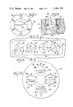
- FIG. 6 is a plan view of an insert according to the invention having indicia for showing the days of the month,
- FIG. 7 is a view similar to FIG. 6 but showing indicia relating to the year date
- FIG. 8 is a top plan illustration of an insert having a series of plugs bearing various indicia
- FIG. 9 is a cross-sectional illustration taken along lines 9--9 of FIG. 8 showing an alternative form of the insert according to the invention.
- FIG. 10 is another embodiment of the invention having a circular insert with a series of plugs spaced from one another and arranged in a circular configuration.
- a mold incorporating a removable insert according to the invention is shown generally at 10 in FIG. 1.
- the mold 10 includes a mold core or male part 12, a mold cavity or female part 14, and a mold inlet 16 having a gate 18 through which plastic material to be formed within the mold 10 is injected.
- a molded part is shown generally at 20 in FIG. 1.
- An insert 22 according to the invention is located within an aperture formed in the mold core 12.
- the insert 22 is pressure fitted within the aperture in the mold core so that the insert 22 is held securely in place.
- a bore 24 leads from the insert 22 within the mold core 12 so that the insert 22 can be removed, if required, by passing a long tool through the bore 24 to tap the insert 22 from the mold core 12.
- FIG. 2 illustrates a mold 10' similar to that of FIG. 1. However, in this embodiment of the invention, the insert 22 is located in the mold cavity 14. Otherwise, the mold 10' is identical to the mold 10 of FIG. 1.
- FIG. 3 illustrates a series of inserts 26, 28, 30 and 32 installed within a mold body 34.
- Each of the inserts 26 through 32 includes a series of indicia 36.
- the inserts 26 through 32 and indicia 36 are reversed so that impressions on a molded article are easily readable.
- each of the inserts 26 through 32 is identical and therefore only the insert 28, illustrated in enlarged cross-section in FIG. 4, will be discussed in detail, it being understood that the description of the insert 28 is equally applicable to the inserts 26, 30 and 32.
- the insert 28 includes two primary portions, a plug body 38 and a plug 40.
- the plug body 38 includes a central bore 42 in which the plug 40 is installed.
- One end of the plug 40, designated 44, includes a mold engaging surface 46.
- the plug end 40 fills the bore 42 to the extent of the plug end 44, as shown.
- the mold engaging surface 46 is contiguous with the face 48 of the plug body 38.
- the surface 46 is contoured to conform to the adjacent contours of the face 48 and, in the form of the invention shown in FIG. 4, the face 48 and surface 46 are flat.
- the face 48 and surface 46 might be curved or otherwise shaped to conform to the molded part being formed.
- a shank 50 extends from the plug end 44.
- a retention ring 52 is installed in a groove 54 formed about the shank 50 at its distal end.
- the bore 42 includes an annular shoulder 56 extending into the bore as shown, and a spring 58, under compression, is located between the shoulder 56 and retention ring 52.
- the spring 58 bearing between the shoulder 56 and retention ring 52, maintains the plug 40 securely in place within the bore 42 of the insert 28.
- each of the inserts 26 through 32 includes an indicator 60 for selecting certain of the indicia 36. As shown in FIG. 3, each indicator 60 may be pointed toward a certain one of the indicia 36 of each of the inserts 26 through 32.
- the indicator 60 of the plug 40 is engraved into the mold engaging surface 46.
- the plug end 44 includes a transverse slot 62 extending across the mold engaging surface 46.
- the slot 62 is shaped to accommodate the blade of a screwdriver to permit the user to rotate the plug 40 as desired.
- FIG. 5 The embodiment of the invention shown in FIG. 5 is substantially identical to that shown in FIG. 4 with the exception that the indicia 36' and indicator 60' are embossed rather than engraved. With this exception, the insert 28' of FIG. 5 is identical to that of FIG. 4 and the description thereof is therefore not repeated.
- FIGS. 6 and 7 illustrate, respectively, an insert 64 for showing the days of a single month and an insert 66 for indicating one of six successive years.
- the structures of the inserts 64 and 66 are identical to those of either FIG. 4 or 5. Corresponding reference numerals are therefore repeated in FIGS. 6 and 7.
- FIG. 8 illustrates another embodiment of the invention in which a single insert 68 includes four individual plugs 70, 72, 74 and 76.
- the insert 68 is shown installed in a portion of a mold 78.
- the insert 68 includes a series of indicia 80 about each of the plugs 70 through 76, and each plug 70 through 76 carries an indicator 72 and a slot 84 to facilitate rotation of the plug.
- FIG. 9 is a cross-sectional view of the insert 68 taken through the plug 76.
- the plug 76 is installed in the bore 86 in the insert 68, the bore comprising a first bore portion 88 and a larger diameter, second bore portion 90.
- the plug 76 correspondingly includes a first segment 92 occupying the first bore portion 88 and a larger diameter, second segment 94 occupying the second bore portion 90. Since the segment 94 is of a greater dimension than the bore portion 88, the plug 76 is maintained securely within the insert 68, bearing against the mold 78.
- a sealing ring 96 is employed at the juncture of the bore portions 88 and 90 to effect a good seal about the plug 76 and avoid a seepage of plastic material into a bore 98.
- the bore 98 is similar to the bore 24 (FIGS. 1 and 2) and is used when necessary for removal of the insert 68 from the mold 78.
- FIG. 10 illustrates another embodiment of the invention in which four plugs 100, 102, 104 and 106 are installed in a mold insert 108.
- the insert 108 carries a series of indicia 110 about each of the plugs 100 through 106 and the structure of the plugs (and corresponding bores within which the plugs 100 through 106 are located) may correspond to any of the embodiments discussed above.
- the plugs 100 through 106 are spaced from one another and are arranged in a circular configuration in the insert 108, the insert 108 therefore being amendable to insulation within a circular bore formed in a mold (not illustrated).
- plugs 100 through 106 and corresponding indicia 110 are shown to represent shift, day, year and month, it should be apparent that a fewer or greater number of plugs can be employed, and the representative indicia changed depending on the use invisioned for the insert 108.
Landscapes
- Engineering & Computer Science (AREA)
- Mechanical Engineering (AREA)
- Manufacturing & Machinery (AREA)
- Moulds For Moulding Plastics Or The Like (AREA)
Abstract
Description
Claims (10)
Priority Applications (1)
| Application Number | Priority Date | Filing Date | Title |
|---|---|---|---|
| US06/356,490 US4384702A (en) | 1982-03-09 | 1982-03-09 | Mold insert |
Applications Claiming Priority (1)
| Application Number | Priority Date | Filing Date | Title |
|---|---|---|---|
| US06/356,490 US4384702A (en) | 1982-03-09 | 1982-03-09 | Mold insert |
Publications (1)
| Publication Number | Publication Date |
|---|---|
| US4384702A true US4384702A (en) | 1983-05-24 |
Family
ID=23401650
Family Applications (1)
| Application Number | Title | Priority Date | Filing Date |
|---|---|---|---|
| US06/356,490 Expired - Lifetime US4384702A (en) | 1982-03-09 | 1982-03-09 | Mold insert |
Country Status (1)
| Country | Link |
|---|---|
| US (1) | US4384702A (en) |
Cited By (49)
| Publication number | Priority date | Publication date | Assignee | Title |
|---|---|---|---|---|
| EP0140384A3 (en) * | 1983-11-03 | 1987-09-02 | TAMPOflex GmbH | Plate for the plate holder of a printing machine of the transfer-pad type |
| US4708314A (en) * | 1985-03-15 | 1987-11-24 | Hasco Normalien Hasenclever & Co. | Adjustable marking device for use in mold wall |
| WO1989005095A1 (en) * | 1987-11-30 | 1989-06-15 | Jeffrey Robinson | Method and mold for imprinting moldable food stuffs and method and apparatus for making the mold |
| FR2644610A1 (en) * | 1989-03-14 | 1990-09-21 | Renault | AUTOMATIC DEVICE FOR NUMBERING WORKPIECES MOLDED |
| DE3931200C1 (en) * | 1989-09-19 | 1990-11-22 | Hasco-Normalien Hasenclever + Co, 5880 Luedenscheid, De | Working unit for injection moulding or press tool - has outer cylindrical ring member in receiving bore hole |
| US4979720A (en) * | 1987-11-30 | 1990-12-25 | Jeffrey Robinson | Injection mold having interchangeable inscription plates |
| US5057000A (en) * | 1990-06-21 | 1991-10-15 | Mangone Peter G Jr | Apparatus for molding sequentially identified products |
| EP0372732A3 (en) * | 1988-12-06 | 1992-01-02 | Euro-Matic Ltd. | Date coding play balls |
| CH679917A5 (en) * | 1989-11-15 | 1992-05-15 | Raichle Sportschuh Ag | Data markings on e.g. injection mouldings - are produced by setting into mould tool e.g. flat plate with markings, each with sec. marking adjusted by screwdriver slot |
| WO1992011102A1 (en) * | 1990-12-19 | 1992-07-09 | Leinovalu Oy | Marking of casting |
| US5295804A (en) * | 1992-07-27 | 1994-03-22 | Dinnan Timothy P | Female mold including decorating insert for differential pressure forming |
| EP0628396A1 (en) * | 1993-06-11 | 1994-12-14 | Alberto Navarra | Marking insert for an injection mould |
| DE4403058C1 (en) * | 1994-02-02 | 1995-02-02 | Eoc Normalien Gmbh & Co Kg | Marking insert for an injection mould |
| DE4330536A1 (en) * | 1993-09-09 | 1995-03-16 | Hasco Normalien Hasenclever Co | Marking insert for an injection mould or compression mould for the processing of plastic compositions, in particular polymer melts |
| EP0670211A1 (en) * | 1994-03-01 | 1995-09-06 | Bernard Picco | Indexable marking device for moulds |
| US5536463A (en) * | 1994-08-19 | 1996-07-16 | Del-Met Corporation | System and method for molding plastic wheel covers |
| EP0756925A1 (en) * | 1995-08-04 | 1997-02-05 | Matsushita Electronics Corporation | Resin sealing die, resin-sealed-type semiconductor device and method of manufacturing the device |
| US5609810A (en) * | 1994-01-31 | 1997-03-11 | Fuji Photo Film Co., Ltd. | Method of molding cases used in information detection hole system and apparatus therefor |
| US5620716A (en) * | 1994-05-03 | 1997-04-15 | Opitz Gmbh | Time stamp for insertion into a mould for metal working or plastics processing |
| DE29717308U1 (en) | 1997-09-27 | 1997-12-04 | Wietrzynski, Bernhard, 74177 Bad Friedrichshall | Date clock |
| DE19700418C1 (en) * | 1997-01-09 | 1998-02-05 | Hasco Normalien Hasenclever Co | Product marking insert for a press or injection tool, especially a plastics injection tool |
| US5788872A (en) * | 1996-07-18 | 1998-08-04 | Uratani; Hideki | Removable marking device for mold |
| US5817349A (en) * | 1995-03-03 | 1998-10-06 | Pruna; Alberto Navarra | Marker device insertable in plastic injection molds |
| US5853606A (en) * | 1998-01-05 | 1998-12-29 | Boskovic; Borislav | Mold identification device |
| US5894005A (en) * | 1996-04-08 | 1999-04-13 | Ford Global Technologies, Inc. | System for identifying castings and for tracking casting process parameters |
| US5902512A (en) * | 1998-01-28 | 1999-05-11 | Streit; Kenneth F. | Adjustable date stamp mold insert |
| USD417621S (en) * | 1998-04-02 | 1999-12-14 | Owens-Brockway Plastic Products Inc. | Bottle |
| DE19502564C2 (en) * | 1995-01-27 | 2000-06-21 | Markus Hintennach | Device for the continuous marking of parts produced by die casting or injection molding |
| US6149420A (en) * | 1997-02-20 | 2000-11-21 | Samsung Electronics Co., Ltd. | Mold with indicia forming changeable core |
| FR2806027A1 (en) * | 2000-03-08 | 2001-09-14 | Anserville Tech | injection mold has rotatable marking device(s) forming part of mold cavity for applying serial number, etc. to molded articles and operable from outside closed mold |
| US6308929B1 (en) * | 1998-10-22 | 2001-10-30 | Klaus A. Wieder | Mold insert |
| US20020100860A1 (en) * | 1999-09-09 | 2002-08-01 | Wieder Klaus A. | Mold vent and method |
| US6554245B2 (en) * | 1996-07-16 | 2003-04-29 | Bernard Picco | Marking device for a mould |
| US6582197B2 (en) * | 2001-02-22 | 2003-06-24 | Simon E. Coulson | Method of investment casting with casting identification |
| US6780362B1 (en) * | 2000-05-10 | 2004-08-24 | Unilever Home & Personal Care, Usa Division Of Conopco, Inc. | Modular mold and die assembly |
| US20040178319A1 (en) * | 2003-02-27 | 2004-09-16 | Pruna Alberto Navarra | Universal marking insert for injection moulds |
| DE102004046353A1 (en) * | 2004-09-24 | 2006-04-06 | Daimlerchrysler Ag | Embossing machine, with a carrier body, has an embossing module as a revolver drum with dies in chambers to be positioned around the center axis for selection and locking |
| US20060166381A1 (en) * | 2005-01-26 | 2006-07-27 | Lange Bernhard P | Mold cavity identification markings for IC packages |
| WO2006121439A1 (en) * | 2005-05-10 | 2006-11-16 | Michelin Recherche Et Technique S.A. | Readily interchangeable marker for a tire mold |
| US20070145232A1 (en) * | 2005-08-24 | 2007-06-28 | Uratanishoji Kabushiki Kaisha | Removable marking device for a mold |
| US20070166423A1 (en) * | 2006-01-18 | 2007-07-19 | Tuck Daniel B | Rubber and plastic mold adjustable date stamp insert |
| US20070190204A1 (en) * | 2006-01-18 | 2007-08-16 | Hon Hai Precision Industry Co., Ltd. | Mold for forming workpiece |
| US20080290248A1 (en) * | 2007-03-22 | 2008-11-27 | Universal Trim Supply, Co., Ltd. | Date code marking system |
| US20090188399A1 (en) * | 2005-08-24 | 2009-07-30 | Uratanishoji Kabushiki Kaisha | Marking device |
| US20090224135A1 (en) * | 2008-03-06 | 2009-09-10 | Hon Hai Precision Industry Co., Ltd. | Mold unit with replaceable mold core holder |
| US20090273120A1 (en) * | 2008-02-22 | 2009-11-05 | Vandor Corporation | Method of molding reel flanges and tool arrangement thereof |
| US20100163706A1 (en) * | 2008-12-30 | 2010-07-01 | Hong Fu Jin Precision Industry (Shenzhen) Co., Ltd. | Stamping mold adapted to stamp characters in workpieces |
| US20110210477A1 (en) * | 2010-03-01 | 2011-09-01 | Shu Chuen Ho | Apparatus for molding electronic components |
| CN106424432A (en) * | 2016-08-30 | 2017-02-22 | 江西东方豹紧固件有限公司 | Automatic dotting nut machining equipment |
Citations (13)
| Publication number | Priority date | Publication date | Assignee | Title |
|---|---|---|---|---|
| US180450A (en) * | 1876-08-01 | Improvement in glass-molds | ||
| US490966A (en) * | 1893-01-31 | Label-former for glass-molds | ||
| US992830A (en) * | 1911-03-28 | 1911-05-23 | Walter S Wheaton | Bottle-mold. |
| US1576212A (en) * | 1924-07-10 | 1926-03-09 | O'neill Frank | Mold marker mounting |
| US2296016A (en) * | 1940-11-12 | 1942-09-15 | Akron Standard Mold Co | Tire mold |
| US2679663A (en) * | 1950-02-01 | 1954-06-01 | Goodrich Co B F | Marking of molded articles |
| US3160928A (en) * | 1963-04-02 | 1964-12-15 | C M Smillie And Company | Core mold vent plug |
| US3230590A (en) * | 1963-12-18 | 1966-01-25 | Altamil Corp | Modular pattern equipment |
| US3262404A (en) * | 1964-05-29 | 1966-07-26 | Mirro Aluminum Company | Cookie press |
| US3344477A (en) * | 1964-10-05 | 1967-10-03 | Stokis Edmond | Valve for molding of plastic under pressure |
| US3518335A (en) * | 1967-04-13 | 1970-06-30 | Uniroyal Inc | Tire vulcanizing method |
| US3581374A (en) * | 1968-03-08 | 1971-06-01 | Frederic S Geary | Method for printing matrixes |
| US4254933A (en) * | 1979-12-26 | 1981-03-10 | Netto Eduardo D L C | Mold for injection molding |
-
1982
- 1982-03-09 US US06/356,490 patent/US4384702A/en not_active Expired - Lifetime
Patent Citations (13)
| Publication number | Priority date | Publication date | Assignee | Title |
|---|---|---|---|---|
| US180450A (en) * | 1876-08-01 | Improvement in glass-molds | ||
| US490966A (en) * | 1893-01-31 | Label-former for glass-molds | ||
| US992830A (en) * | 1911-03-28 | 1911-05-23 | Walter S Wheaton | Bottle-mold. |
| US1576212A (en) * | 1924-07-10 | 1926-03-09 | O'neill Frank | Mold marker mounting |
| US2296016A (en) * | 1940-11-12 | 1942-09-15 | Akron Standard Mold Co | Tire mold |
| US2679663A (en) * | 1950-02-01 | 1954-06-01 | Goodrich Co B F | Marking of molded articles |
| US3160928A (en) * | 1963-04-02 | 1964-12-15 | C M Smillie And Company | Core mold vent plug |
| US3230590A (en) * | 1963-12-18 | 1966-01-25 | Altamil Corp | Modular pattern equipment |
| US3262404A (en) * | 1964-05-29 | 1966-07-26 | Mirro Aluminum Company | Cookie press |
| US3344477A (en) * | 1964-10-05 | 1967-10-03 | Stokis Edmond | Valve for molding of plastic under pressure |
| US3518335A (en) * | 1967-04-13 | 1970-06-30 | Uniroyal Inc | Tire vulcanizing method |
| US3581374A (en) * | 1968-03-08 | 1971-06-01 | Frederic S Geary | Method for printing matrixes |
| US4254933A (en) * | 1979-12-26 | 1981-03-10 | Netto Eduardo D L C | Mold for injection molding |
Cited By (66)
| Publication number | Priority date | Publication date | Assignee | Title |
|---|---|---|---|---|
| EP0140384A3 (en) * | 1983-11-03 | 1987-09-02 | TAMPOflex GmbH | Plate for the plate holder of a printing machine of the transfer-pad type |
| US4708314A (en) * | 1985-03-15 | 1987-11-24 | Hasco Normalien Hasenclever & Co. | Adjustable marking device for use in mold wall |
| EP0194522A3 (en) * | 1985-03-15 | 1988-09-21 | Hasenclever + Co Hasco-Normalien | Injection moulding or press tool for working plastic materials |
| WO1989005095A1 (en) * | 1987-11-30 | 1989-06-15 | Jeffrey Robinson | Method and mold for imprinting moldable food stuffs and method and apparatus for making the mold |
| US4979720A (en) * | 1987-11-30 | 1990-12-25 | Jeffrey Robinson | Injection mold having interchangeable inscription plates |
| EP0372732A3 (en) * | 1988-12-06 | 1992-01-02 | Euro-Matic Ltd. | Date coding play balls |
| FR2644610A1 (en) * | 1989-03-14 | 1990-09-21 | Renault | AUTOMATIC DEVICE FOR NUMBERING WORKPIECES MOLDED |
| DE3931200C1 (en) * | 1989-09-19 | 1990-11-22 | Hasco-Normalien Hasenclever + Co, 5880 Luedenscheid, De | Working unit for injection moulding or press tool - has outer cylindrical ring member in receiving bore hole |
| CH679917A5 (en) * | 1989-11-15 | 1992-05-15 | Raichle Sportschuh Ag | Data markings on e.g. injection mouldings - are produced by setting into mould tool e.g. flat plate with markings, each with sec. marking adjusted by screwdriver slot |
| US5057000A (en) * | 1990-06-21 | 1991-10-15 | Mangone Peter G Jr | Apparatus for molding sequentially identified products |
| WO1992011102A1 (en) * | 1990-12-19 | 1992-07-09 | Leinovalu Oy | Marking of casting |
| US5295804A (en) * | 1992-07-27 | 1994-03-22 | Dinnan Timothy P | Female mold including decorating insert for differential pressure forming |
| EP0628396A1 (en) * | 1993-06-11 | 1994-12-14 | Alberto Navarra | Marking insert for an injection mould |
| DE4330536A1 (en) * | 1993-09-09 | 1995-03-16 | Hasco Normalien Hasenclever Co | Marking insert for an injection mould or compression mould for the processing of plastic compositions, in particular polymer melts |
| US5609810A (en) * | 1994-01-31 | 1997-03-11 | Fuji Photo Film Co., Ltd. | Method of molding cases used in information detection hole system and apparatus therefor |
| DE4403058C1 (en) * | 1994-02-02 | 1995-02-02 | Eoc Normalien Gmbh & Co Kg | Marking insert for an injection mould |
| ES2114415A1 (en) * | 1994-02-02 | 1998-05-16 | E O C Normalien Gmbh & Co Kg | Marking insert for an injection mould |
| EP0670211A1 (en) * | 1994-03-01 | 1995-09-06 | Bernard Picco | Indexable marking device for moulds |
| FR2716825A1 (en) * | 1994-03-01 | 1995-09-08 | Picco Bernard | Indexable marking device for mold |
| US5620716A (en) * | 1994-05-03 | 1997-04-15 | Opitz Gmbh | Time stamp for insertion into a mould for metal working or plastics processing |
| US5536463A (en) * | 1994-08-19 | 1996-07-16 | Del-Met Corporation | System and method for molding plastic wheel covers |
| DE19502564C2 (en) * | 1995-01-27 | 2000-06-21 | Markus Hintennach | Device for the continuous marking of parts produced by die casting or injection molding |
| US5817349A (en) * | 1995-03-03 | 1998-10-06 | Pruna; Alberto Navarra | Marker device insertable in plastic injection molds |
| EP0756925A1 (en) * | 1995-08-04 | 1997-02-05 | Matsushita Electronics Corporation | Resin sealing die, resin-sealed-type semiconductor device and method of manufacturing the device |
| US5817208A (en) * | 1995-08-04 | 1998-10-06 | Matsushita Electronics Corporation | Resin sealing die, resin-sealed-type semiconductor device and method of manufacturing the device |
| US5894005A (en) * | 1996-04-08 | 1999-04-13 | Ford Global Technologies, Inc. | System for identifying castings and for tracking casting process parameters |
| US6554245B2 (en) * | 1996-07-16 | 2003-04-29 | Bernard Picco | Marking device for a mould |
| US5788872A (en) * | 1996-07-18 | 1998-08-04 | Uratani; Hideki | Removable marking device for mold |
| DE19700418C1 (en) * | 1997-01-09 | 1998-02-05 | Hasco Normalien Hasenclever Co | Product marking insert for a press or injection tool, especially a plastics injection tool |
| US6149420A (en) * | 1997-02-20 | 2000-11-21 | Samsung Electronics Co., Ltd. | Mold with indicia forming changeable core |
| DE29717308U1 (en) | 1997-09-27 | 1997-12-04 | Wietrzynski, Bernhard, 74177 Bad Friedrichshall | Date clock |
| US5853606A (en) * | 1998-01-05 | 1998-12-29 | Boskovic; Borislav | Mold identification device |
| US5902512A (en) * | 1998-01-28 | 1999-05-11 | Streit; Kenneth F. | Adjustable date stamp mold insert |
| USD417621S (en) * | 1998-04-02 | 1999-12-14 | Owens-Brockway Plastic Products Inc. | Bottle |
| US6308929B1 (en) * | 1998-10-22 | 2001-10-30 | Klaus A. Wieder | Mold insert |
| US20020053633A1 (en) * | 1998-10-22 | 2002-05-09 | Wieder Klaus A. | Ejector pin and method |
| US7131625B2 (en) | 1998-10-22 | 2006-11-07 | Wieder Klaus A | Ejector pin and method |
| US6827569B2 (en) | 1999-09-09 | 2004-12-07 | Klaus A. Wieder | Mold vent and method |
| US20020100860A1 (en) * | 1999-09-09 | 2002-08-01 | Wieder Klaus A. | Mold vent and method |
| FR2806027A1 (en) * | 2000-03-08 | 2001-09-14 | Anserville Tech | injection mold has rotatable marking device(s) forming part of mold cavity for applying serial number, etc. to molded articles and operable from outside closed mold |
| US6780362B1 (en) * | 2000-05-10 | 2004-08-24 | Unilever Home & Personal Care, Usa Division Of Conopco, Inc. | Modular mold and die assembly |
| US6582197B2 (en) * | 2001-02-22 | 2003-06-24 | Simon E. Coulson | Method of investment casting with casting identification |
| GB2372472B (en) * | 2001-02-22 | 2005-09-07 | Howmet Res Corp | Method of investment casting with casting identification |
| US6889954B2 (en) * | 2003-02-27 | 2005-05-10 | Comercial De Utiles Y Moldes, S.A. | Universal marking insert for injection moulds |
| US20040178319A1 (en) * | 2003-02-27 | 2004-09-16 | Pruna Alberto Navarra | Universal marking insert for injection moulds |
| DE102004046353A1 (en) * | 2004-09-24 | 2006-04-06 | Daimlerchrysler Ag | Embossing machine, with a carrier body, has an embossing module as a revolver drum with dies in chambers to be positioned around the center axis for selection and locking |
| DE102004046353B4 (en) * | 2004-09-24 | 2006-09-28 | Daimlerchrysler Ag | embosser |
| US20060166381A1 (en) * | 2005-01-26 | 2006-07-27 | Lange Bernhard P | Mold cavity identification markings for IC packages |
| WO2006121439A1 (en) * | 2005-05-10 | 2006-11-16 | Michelin Recherche Et Technique S.A. | Readily interchangeable marker for a tire mold |
| US8011638B2 (en) * | 2005-08-24 | 2011-09-06 | Uratanishoji Kabushiki Kaisha | Marking device |
| US20070145232A1 (en) * | 2005-08-24 | 2007-06-28 | Uratanishoji Kabushiki Kaisha | Removable marking device for a mold |
| US7503542B2 (en) * | 2005-08-24 | 2009-03-17 | Uratanishoji Kabushiki Kaisha (Japan Corporation) | Removable marking device for a mold |
| US20090188399A1 (en) * | 2005-08-24 | 2009-07-30 | Uratanishoji Kabushiki Kaisha | Marking device |
| US20070166423A1 (en) * | 2006-01-18 | 2007-07-19 | Tuck Daniel B | Rubber and plastic mold adjustable date stamp insert |
| US20070190204A1 (en) * | 2006-01-18 | 2007-08-16 | Hon Hai Precision Industry Co., Ltd. | Mold for forming workpiece |
| US7431580B2 (en) * | 2006-01-18 | 2008-10-07 | Hon Hai Precision Industry Co., Ltd. | Mold for forming workpiece |
| US20080290248A1 (en) * | 2007-03-22 | 2008-11-27 | Universal Trim Supply, Co., Ltd. | Date code marking system |
| US7637473B2 (en) * | 2007-03-22 | 2009-12-29 | Universal Trim Supply Co., Ltd. | Date code marking system |
| US20090273120A1 (en) * | 2008-02-22 | 2009-11-05 | Vandor Corporation | Method of molding reel flanges and tool arrangement thereof |
| US8349242B2 (en) * | 2008-02-22 | 2013-01-08 | Vandor Corporation | Method of molding reel flanges and tool arrangement thereof |
| US20090224135A1 (en) * | 2008-03-06 | 2009-09-10 | Hon Hai Precision Industry Co., Ltd. | Mold unit with replaceable mold core holder |
| US20100163706A1 (en) * | 2008-12-30 | 2010-07-01 | Hong Fu Jin Precision Industry (Shenzhen) Co., Ltd. | Stamping mold adapted to stamp characters in workpieces |
| US8057211B2 (en) * | 2008-12-30 | 2011-11-15 | Hong Fu Jin Precision Industry (Shenzhen) Co., Ltd. | Stamping mold adapted to stamp characters in workpieces |
| US20110210477A1 (en) * | 2010-03-01 | 2011-09-01 | Shu Chuen Ho | Apparatus for molding electronic components |
| US8794952B2 (en) * | 2010-03-01 | 2014-08-05 | Asm Technology Singapore Pte Ltd | Apparatus for molding electronic components |
| CN106424432A (en) * | 2016-08-30 | 2017-02-22 | 江西东方豹紧固件有限公司 | Automatic dotting nut machining equipment |
Similar Documents
| Publication | Publication Date | Title |
|---|---|---|
| US4384702A (en) | Mold insert | |
| US5788872A (en) | Removable marking device for mold | |
| US2586978A (en) | Inlay for molded plastic articles | |
| US6308929B1 (en) | Mold insert | |
| US5902512A (en) | Adjustable date stamp mold insert | |
| US3760969A (en) | Container closure | |
| SG82692G (en) | Injection moulding or press tool for working plastic materials | |
| ES289057U (en) | Closure cap for a container and method for its manufacture. | |
| GB1478420A (en) | Apparatus for moulding safety caps | |
| GB1287735A (en) | Valves for pressurized dispensing containers | |
| CN101069986A (en) | A date code marking device for molded plastic products | |
| US1913807A (en) | Tube cap | |
| EP0389560B1 (en) | Mold for imprinting moldable food stuffs and method and apparatus for making the mold | |
| US4063861A (en) | Tire mold | |
| US3100318A (en) | Mold identification plug | |
| US2851731A (en) | Method of molding arcuate indiciacontaining articles | |
| US1445745A (en) | Method of marking tires | |
| US1879387A (en) | Stamp | |
| JPH04126838U (en) | Rubber product mold | |
| US11926083B2 (en) | Dating system for molds | |
| JPH0410408B2 (en) | ||
| KR100319403B1 (en) | Date marked pin for molding | |
| US5373332A (en) | Plastic spectacle lens and method for making | |
| SU631239A1 (en) | Male die set holder | |
| CN201102285Y (en) | Mold with date progressive increase mark |
Legal Events
| Date | Code | Title | Description |
|---|---|---|---|
| STCF | Information on status: patent grant |
Free format text: PATENTED CASE |
|
| MAFP | Maintenance fee payment |
Free format text: PAYMENT OF MAINTENANCE FEE, 4TH YEAR, PL 96-517 (ORIGINAL EVENT CODE: M170); ENTITY STATUS OF PATENT OWNER: SMALL ENTITY Year of fee payment: 4 |
|
| MAFP | Maintenance fee payment |
Free format text: PAYMENT OF MAINTENANCE FEE, 8TH YEAR, PL 96-517 (ORIGINAL EVENT CODE: M171); ENTITY STATUS OF PATENT OWNER: SMALL ENTITY Year of fee payment: 8 |
|
| FEPP | Fee payment procedure |
Free format text: PAYOR NUMBER ASSIGNED (ORIGINAL EVENT CODE: ASPN); ENTITY STATUS OF PATENT OWNER: SMALL ENTITY |
|
| MAFP | Maintenance fee payment |
Free format text: PAYMENT OF MAINTENANCE FEE, 12TH YR, SMALL ENTITY (ORIGINAL EVENT CODE: M285); ENTITY STATUS OF PATENT OWNER: SMALL ENTITY Year of fee payment: 12 |