US4292977A - Method and device for representing electrical spatial lines and spatial images - Google Patents
Method and device for representing electrical spatial lines and spatial images Download PDFInfo
- Publication number
- US4292977A US4292977A US06/037,119 US3711979A US4292977A US 4292977 A US4292977 A US 4292977A US 3711979 A US3711979 A US 3711979A US 4292977 A US4292977 A US 4292977A
- Authority
- US
- United States
- Prior art keywords
- spatial
- images
- curves
- coordinates
- memory
- Prior art date
- Legal status (The legal status is an assumption and is not a legal conclusion. Google has not performed a legal analysis and makes no representation as to the accuracy of the status listed.)
- Expired - Lifetime
Links
- 238000000034 method Methods 0.000 title claims abstract description 8
- 230000015654 memory Effects 0.000 claims abstract description 18
- 230000000747 cardiac effect Effects 0.000 claims abstract 3
- 238000005282 brightening Methods 0.000 claims description 7
- 238000005259 measurement Methods 0.000 claims description 5
- 238000012360 testing method Methods 0.000 claims description 4
- 239000004072 C09CA03 - Valsartan Substances 0.000 claims 1
- 230000004913 activation Effects 0.000 claims 1
- 238000010586 diagram Methods 0.000 description 2
- 238000011156 evaluation Methods 0.000 description 2
- 239000003550 marker Substances 0.000 description 2
- 238000012800 visualization Methods 0.000 description 2
- 101100386054 Saccharomyces cerevisiae (strain ATCC 204508 / S288c) CYS3 gene Proteins 0.000 description 1
- 210000000038 chest Anatomy 0.000 description 1
- 230000000295 complement effect Effects 0.000 description 1
- 238000007435 diagnostic evaluation Methods 0.000 description 1
- 230000000694 effects Effects 0.000 description 1
- 239000011521 glass Substances 0.000 description 1
- 238000003384 imaging method Methods 0.000 description 1
- 230000003287 optical effect Effects 0.000 description 1
- 230000008447 perception Effects 0.000 description 1
- 230000033764 rhythmic process Effects 0.000 description 1
- 101150035983 str1 gene Proteins 0.000 description 1
- 230000000007 visual effect Effects 0.000 description 1
Images

Classifications
-
- A—HUMAN NECESSITIES
- A61—MEDICAL OR VETERINARY SCIENCE; HYGIENE
- A61B—DIAGNOSIS; SURGERY; IDENTIFICATION
- A61B5/00—Measuring for diagnostic purposes; Identification of persons
- A61B5/24—Detecting, measuring or recording bioelectric or biomagnetic signals of the body or parts thereof
- A61B5/316—Modalities, i.e. specific diagnostic methods
- A61B5/318—Heart-related electrical modalities, e.g. electrocardiography [ECG]
- A61B5/333—Recording apparatus specially adapted therefor
- A61B5/335—Recording apparatus specially adapted therefor using integrated circuit memory devices
-
- A—HUMAN NECESSITIES
- A61—MEDICAL OR VETERINARY SCIENCE; HYGIENE
- A61B—DIAGNOSIS; SURGERY; IDENTIFICATION
- A61B5/00—Measuring for diagnostic purposes; Identification of persons
- A61B5/24—Detecting, measuring or recording bioelectric or biomagnetic signals of the body or parts thereof
- A61B5/316—Modalities, i.e. specific diagnostic methods
- A61B5/318—Heart-related electrical modalities, e.g. electrocardiography [ECG]
- A61B5/339—Displays specially adapted therefor
- A61B5/341—Vectorcardiography [VCG]
-
- G—PHYSICS
- G01—MEASURING; TESTING
- G01R—MEASURING ELECTRIC VARIABLES; MEASURING MAGNETIC VARIABLES
- G01R13/00—Arrangements for displaying electric variables or waveforms
- G01R13/20—Cathode-ray oscilloscopes
- G01R13/206—Arrangements for obtaining a 3- dimensional representation
-
- Y—GENERAL TAGGING OF NEW TECHNOLOGICAL DEVELOPMENTS; GENERAL TAGGING OF CROSS-SECTIONAL TECHNOLOGIES SPANNING OVER SEVERAL SECTIONS OF THE IPC; TECHNICAL SUBJECTS COVERED BY FORMER USPC CROSS-REFERENCE ART COLLECTIONS [XRACs] AND DIGESTS
- Y10—TECHNICAL SUBJECTS COVERED BY FORMER USPC
- Y10S—TECHNICAL SUBJECTS COVERED BY FORMER USPC CROSS-REFERENCE ART COLLECTIONS [XRACs] AND DIGESTS
- Y10S128/00—Surgery
- Y10S128/916—Ultrasound 3-D imaging
Definitions
- the invention relates to a method and an arrangement for representing electrical spatial curves and spatial images, especially of electrically reproduced ultrasonic images, X-ray images or of vector loops customary in cardiology.
- the stated problem is solved by the method according to the invention by the provision that coordinates of the action currents occurring in time in the x, y and z direction are kept available separately in an electronic memory; that in a first computer, transformed x-, y- and z- coordinates of the spatial curve or the spatial image tilted by any desired angle ⁇ and rotated by any desired angle ⁇ are calculated, and the transformed coordinates x, y and z are displayed two-dimensionally on the picture screen of an oscilloscope; and a three-dimensional visualization is obtained by tilting and rotating.
- the coordinates x, y and z are fed to a second computer for calculating the coordinates of the central projections of the transformed three-dimensional curve or the three-dimensional image from two viewing points, in order to display these central projections for each viewing point separately in two pictures on a picture screen, which are perceived as three-dimensional by means of an optical system.
- the spatial curves and spatial images can be moved manually by separate adjustment of the angles ⁇ and ⁇ and can be viewed from any side desired.
- time markers are inserted in the form of lateral jags pointing in arrow fashion in the direction of traversal, the size of the jags depending on the curve velocity.
- the invention facilitates in an outstanding manner the rapid evaluation of the shape and the velocity of complicated three-dimensional curves and is applicable in particular in electrocardioscopy, where it facilitates and speeds up the diagnostic evaluation of electrocardiograms.
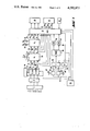
- FIG. 1 shows a block diagram of the stereokinetic vector cardioscope
- FIG. 2 details of time marking
- FIG. 3 a pulse diagram
- FIGS. 4 to 6 show screen pictures.
- Bioelectric signals of the heart activity are taken from a test person in a manner known per se by means of electrodes placed on the skin, for instance, by means of the Frank network 1 and are fed to a preamplifier 3 which amplifies the signals to a suitable magnitude, for instance, ⁇ 5 V.
- a preamplifier 3 which amplifies the signals to a suitable magnitude, for instance, ⁇ 5 V.
- the coordinates of the integral vector loop are available with their waveform separated by x-, y- and z- direction, and are stored in real time in an electronic memory 5, 6, 7.
- recording equipment 19 for instance, magnetic tape equipment or a perforated-tape punch for documentation, so that the recorded x-, y- and z coordinates can be put in memory again at any time for further analysis.
- the arrows 21 and 22 shown in the figure from memory 5 for the x-coordinates to the recording equipment 19 indicate the connection between the memory and the recording equipment; the memories 6 and 7 for the y- and z coordinates are connected to the recording equipment in a similar manner.
- the x-, y- and z-coordinates of the memories 5, 6, 7 are fed via lines 24, 25, 26 to a first computer 28.
- the wave shapes of these x-, y- and z-coordinates describe a curve in space.
- the result of these transformed coordinates is fed via the lines 29 to 31, the multiplexer 40 and the lines 43 to 45 to the oscilloscope 42 and can be followed up immediately on the picture screen.
- angles ⁇ and ⁇ can be set into the first computer 28 (for parallel projection) very plainly by a control stick which can be tilted ( ⁇ ) forward and backward and vice-versa and rotated ( ⁇ ) about its axis in both directions.
- the manual movement of the control stick together with the visual observation of the picture screen facilitates the spatial perception of the three-dimensional curve or the three-dimensional image considerably.
- the handle of the control stick is made in the shape of a small bust for correlation reasons.
- the view of the bust in the tilted and rotated condition corresponds to the view of the spatial curve on the picture screen in the same condition.
- the frontal, sagittal and horizontal projections can be felt by detents in the control stick.
- a second computer 34 for central projection
- This second computer 34 permits calculating the coordinates for central projection of the three-dimensionally moving system from two viewing points.
- the eye distance Aa and the viewing distance Ba can be set by two setting elements 32, 33.
- the second computer determines the coordinates xli, xre and y, which serve for the display of two separate images xli/y and xre/y on the picture screen of the oscilloscope (FIG. 6).
- the coordinates x, y and z are switched to the oscilloscope 42 in scalar form, the coordinates x, y and z in orthogonal form or the coordinates xli, xre and y for a stereo display selectably.
- an x-y recorder 48 For direct recording of the coordinates, an x-y recorder 48 is provided.
- the pictures xli/y and xre/y can also be written on top of each other by the x-y recorder on paper with green and red ink, respectively.
- Viewing through glasses of complementary color then also permits one to see the paper image three-dimensionally (anaglyphics method), if the x-, y-, z-system was rotated or tilted as desired.
- the upper sign applies to jags on the port side of the curve and the lower sign to jags on the starboard side.
- the time markers correspond as to size automatically to the size of the written loops:
- a large loop means high velocity, large ⁇ x and ⁇ y and thereby, a large jag.
- a small loop means low velocity, small ⁇ x and ⁇ y and thereby, a small jag.
- the x, y are added or subtracted as the difference of the values x 12 hold, y 12 hold to the respective actual values of x, y.
- a control circuit 50 contains a clock generator, a sweep generator and a circuit for flyback blanking. To the sweep output of the control circuit 50 is connected via a line 52 a Schmitt trigger to each monostable multivibrator 54 and 56, by which the beginning and the end of the brightening, i.e., the beginning and the end of the time measurement are fixed.
- the desired instances for the time measurement can be set at a "start” and a "stop” potentiometer 57 and 58.
- the outputs of the Schmitt triggers 54 and 56 are connected via lines 60, 61 to start and stop imputs of a counter 62 as well as to "on" and “off” inputs of a bistable multivibrator 64. If, for instance, the counter 62 counts with a frequency of 1000 Hz, the counter reading always gives the result of the time measurement in msec.
- the counter content is presented by means of a programmable memory 66 (PROM) via digital-to-analog converters 67 and 68 to the multiplexer 40 which continuously interrogates the result and displays it on the oscilloscope 42.
- the bistable multivibrator 64 is connected via the line 70 to the multiplexer 40 and initiates with its "on" state the brightness control of the monitor.
- FIG. 3 illustrates the control of the trigger 54 and 56 and of the bistable multivibrator 64.
- the instant t 1 of the time axis t is determined by the position of the "start" potentiometer 57.
- the short start pulse of the start trigger 54 appears, which transfers the bistable multivibrator FF 64 into the "on” state.
- the brightness of the cathode ray beam is turned up and the counter 62 started.
- FIG. 4 shows a screen picture with the components x, y and z in scalar presentation.
- the range t mess marked by dashed lines at the sides, is brightened, while the adjoining zones are darkened. The darkening need not be complete; it may be advantageous to show these portions with a dim, just visible brightness.
- the projection plane x/y is shown in orthogonal presentation on the right half of the screen picture, while on the left half, the curve train for the component y is depicted simultaneously in scalar form.
- the duration of the brightened section of the curve is indicated at the lower edge of the picture screen.
- FIG. 6 shows an example for the display for stereoscopic viewing.
- the projection xli/y for the left eye is imaged and to the right, the projection xre/y for the right eye.
- the duration of the brightened section is likewise indicated.
Landscapes
- Health & Medical Sciences (AREA)
- Life Sciences & Earth Sciences (AREA)
- Engineering & Computer Science (AREA)
- Cardiology (AREA)
- Physics & Mathematics (AREA)
- Molecular Biology (AREA)
- Animal Behavior & Ethology (AREA)
- Biomedical Technology (AREA)
- Heart & Thoracic Surgery (AREA)
- Medical Informatics (AREA)
- Biophysics (AREA)
- Surgery (AREA)
- Pathology (AREA)
- General Health & Medical Sciences (AREA)
- Public Health (AREA)
- Veterinary Medicine (AREA)
- Microelectronics & Electronic Packaging (AREA)
- General Physics & Mathematics (AREA)
- Eye Examination Apparatus (AREA)
- Ultra Sonic Daignosis Equipment (AREA)
- Apparatus For Radiation Diagnosis (AREA)
Applications Claiming Priority (4)
| Application Number | Priority Date | Filing Date | Title |
|---|---|---|---|
| DE2819999 | 1978-05-08 | ||
| DE2819999A DE2819999C2 (de) | 1978-05-08 | 1978-05-08 | Verfahren und Anordnung zur Darstellung von elektrischen Raumkurven und Raumbildern |
| DE2908424 | 1979-03-02 | ||
| DE2908424A DE2908424C2 (de) | 1978-05-08 | 1979-03-03 | Verfahren und Anordnung zur Darstellung von elektrischen Raumkurven |
Publications (1)
| Publication Number | Publication Date |
|---|---|
| US4292977A true US4292977A (en) | 1981-10-06 |
Family
ID=25774423
Family Applications (1)
| Application Number | Title | Priority Date | Filing Date |
|---|---|---|---|
| US06/037,119 Expired - Lifetime US4292977A (en) | 1978-05-08 | 1979-05-08 | Method and device for representing electrical spatial lines and spatial images |
Country Status (4)
| Country | Link |
|---|---|
| US (1) | US4292977A (de) |
| AT (1) | ATA339679A (de) |
| DE (1) | DE2908424C2 (de) |
| SE (1) | SE7903429L (de) |
Cited By (18)
| Publication number | Priority date | Publication date | Assignee | Title |
|---|---|---|---|---|
| US4573014A (en) * | 1983-11-09 | 1986-02-25 | Duke University | NMR Imaging method and apparatus |
| US4736295A (en) * | 1984-09-26 | 1988-04-05 | Gerard Lachiver | Method and apparatus for mathematical characterization of the electrocardiogram |
| US4747411A (en) * | 1984-03-28 | 1988-05-31 | National Biochemical Research Foundation | Three-dimensional imaging system |
| US4757822A (en) * | 1985-02-07 | 1988-07-19 | Biotronix S.R.L. | Instrument to detect and represent the cross-sectional variations of a blood vessel |
| US4757820A (en) * | 1985-03-15 | 1988-07-19 | Kabushiki Kaisha Toshiba | Ultrasound therapy system |
| US4922920A (en) * | 1987-01-22 | 1990-05-08 | Willi Studer AB | Process and apparatus for processing signals from a physiologically produced electric field |
| US4949725A (en) * | 1988-07-01 | 1990-08-21 | Bio-Logic Systems Corporation | Apparatus and method for displaying electrical activity generated within a living body |
| US5396890A (en) * | 1993-09-30 | 1995-03-14 | Siemens Medical Systems, Inc. | Three-dimensional scan converter for ultrasound imaging |
| US5687737A (en) * | 1992-10-09 | 1997-11-18 | Washington University | Computerized three-dimensional cardiac mapping with interactive visual displays |
| US5803084A (en) * | 1996-12-05 | 1998-09-08 | Olson; Charles | Three dimensional vector cardiographic display and method for displaying same |
| US6228028B1 (en) | 1996-11-07 | 2001-05-08 | Tomtec Imaging Systems Gmbh | Method and apparatus for ultrasound image reconstruction |
| US20040111021A1 (en) * | 2002-12-09 | 2004-06-10 | Olson Charles W. | Three dimensional vector cardiograph and method for detecting and monitoring ischemic events |
| US6804550B1 (en) * | 1999-09-29 | 2004-10-12 | Draeger Medical Systems, Inc. | Method and apparatus for frank lead reconstruction from derived chest leads |
| US20090195536A1 (en) * | 2008-02-04 | 2009-08-06 | Justin Ralph Louise | System for three-dimensional rendering of electrical test and measurement signals |
| US7751874B2 (en) | 2005-04-25 | 2010-07-06 | Charles Olson | Display for ECG diagnostics |
| US20100249622A1 (en) * | 2005-04-25 | 2010-09-30 | Charles Olson | Location and displaying an ischemic region for ecg diagnostics |
| US8641210B2 (en) | 2011-11-30 | 2014-02-04 | Izi Medical Products | Retro-reflective marker including colored mounting portion |
| US8661573B2 (en) | 2012-02-29 | 2014-03-04 | Izi Medical Products | Protective cover for medical device having adhesive mechanism |
Families Citing this family (1)
| Publication number | Priority date | Publication date | Assignee | Title |
|---|---|---|---|---|
| IL67815A (en) * | 1982-02-12 | 1988-01-31 | Sanz Ernst | Method and apparatus for cardiogonometry |
Citations (8)
| Publication number | Priority date | Publication date | Assignee | Title |
|---|---|---|---|---|
| US3186403A (en) * | 1962-11-13 | 1965-06-01 | Itt | Perspective vectorcardioscope |
| US3671730A (en) * | 1969-03-24 | 1972-06-20 | Marc Norbert Collet | Electronic device for plane graphical representation with perspective effect |
| US3884221A (en) * | 1969-06-10 | 1975-05-20 | George Eastman | Method for the construction and diagnosis of three dimensional ectocariagrams |
| FR2354598A1 (fr) * | 1976-06-11 | 1978-01-06 | Anvar | Calculateur analogique de perspectives |
| US4086492A (en) * | 1976-01-21 | 1978-04-25 | Emi Limited | Display apparatus for use in radiography |
| US4100916A (en) * | 1976-04-27 | 1978-07-18 | King Donald L | Three-dimensional ultrasonic imaging of animal soft tissue |
| DE2804732A1 (de) * | 1977-02-02 | 1978-08-03 | Emi Ltd | Geraet zur verarbeitung von werten einer quantitaet, beispielsweise der absorption von roentgenstrahlung |
| US4141347A (en) * | 1976-09-21 | 1979-02-27 | Sri International | Real-time ultrasonic B-scan imaging and Doppler profile display system and method |
-
1979
- 1979-03-03 DE DE2908424A patent/DE2908424C2/de not_active Expired
- 1979-04-19 SE SE7903429A patent/SE7903429L/xx not_active Application Discontinuation
- 1979-05-07 AT AT0339679A patent/ATA339679A/de not_active IP Right Cessation
- 1979-05-08 US US06/037,119 patent/US4292977A/en not_active Expired - Lifetime
Patent Citations (8)
| Publication number | Priority date | Publication date | Assignee | Title |
|---|---|---|---|---|
| US3186403A (en) * | 1962-11-13 | 1965-06-01 | Itt | Perspective vectorcardioscope |
| US3671730A (en) * | 1969-03-24 | 1972-06-20 | Marc Norbert Collet | Electronic device for plane graphical representation with perspective effect |
| US3884221A (en) * | 1969-06-10 | 1975-05-20 | George Eastman | Method for the construction and diagnosis of three dimensional ectocariagrams |
| US4086492A (en) * | 1976-01-21 | 1978-04-25 | Emi Limited | Display apparatus for use in radiography |
| US4100916A (en) * | 1976-04-27 | 1978-07-18 | King Donald L | Three-dimensional ultrasonic imaging of animal soft tissue |
| FR2354598A1 (fr) * | 1976-06-11 | 1978-01-06 | Anvar | Calculateur analogique de perspectives |
| US4141347A (en) * | 1976-09-21 | 1979-02-27 | Sri International | Real-time ultrasonic B-scan imaging and Doppler profile display system and method |
| DE2804732A1 (de) * | 1977-02-02 | 1978-08-03 | Emi Ltd | Geraet zur verarbeitung von werten einer quantitaet, beispielsweise der absorption von roentgenstrahlung |
Non-Patent Citations (4)
| Title |
|---|
| Katz, G. et al., "Capturing the Third Dimension", Computer Decisions, Oct. 1970, pp. 50-53. * |
| Moritz, W. E. et al., "A uP-Based Spatial Locating System for Use with Diag. UTS", IEEE Proc. vol. 64, No. 6, pp. 966-974, Jun. 1976. * |
| Plott; H. H. et al., "A Real Time Stereoscopic Small Computer Graphics Display System", IEEE Trans. on Systems, Man & Cyber. vol. 5, No. 5 Sep. 1975, pp. 527-533. * |
| Silcocks, H. et al., "Various Methods of Displaying Computer-Generated 3-D VCG's", Proc. 7th Ann. Biol. Sci. Instr. Symp., Ann Arbor, Mich. May 1969, pp. 37-43. * |
Cited By (34)
| Publication number | Priority date | Publication date | Assignee | Title |
|---|---|---|---|---|
| US4573014A (en) * | 1983-11-09 | 1986-02-25 | Duke University | NMR Imaging method and apparatus |
| US4747411A (en) * | 1984-03-28 | 1988-05-31 | National Biochemical Research Foundation | Three-dimensional imaging system |
| US4821728A (en) * | 1984-03-28 | 1989-04-18 | National Biomedical Research Foundation | Three-dimensional imaging system |
| USRE34566E (en) * | 1984-03-28 | 1994-03-22 | National Biomedical Research Foundation | Three-dimensional imaging system |
| US4736295A (en) * | 1984-09-26 | 1988-04-05 | Gerard Lachiver | Method and apparatus for mathematical characterization of the electrocardiogram |
| US4757822A (en) * | 1985-02-07 | 1988-07-19 | Biotronix S.R.L. | Instrument to detect and represent the cross-sectional variations of a blood vessel |
| US4757820A (en) * | 1985-03-15 | 1988-07-19 | Kabushiki Kaisha Toshiba | Ultrasound therapy system |
| US4922920A (en) * | 1987-01-22 | 1990-05-08 | Willi Studer AB | Process and apparatus for processing signals from a physiologically produced electric field |
| US4949725A (en) * | 1988-07-01 | 1990-08-21 | Bio-Logic Systems Corporation | Apparatus and method for displaying electrical activity generated within a living body |
| US5687737A (en) * | 1992-10-09 | 1997-11-18 | Washington University | Computerized three-dimensional cardiac mapping with interactive visual displays |
| US5396890A (en) * | 1993-09-30 | 1995-03-14 | Siemens Medical Systems, Inc. | Three-dimensional scan converter for ultrasound imaging |
| US6228028B1 (en) | 1996-11-07 | 2001-05-08 | Tomtec Imaging Systems Gmbh | Method and apparatus for ultrasound image reconstruction |
| US5803084A (en) * | 1996-12-05 | 1998-09-08 | Olson; Charles | Three dimensional vector cardiographic display and method for displaying same |
| US6804550B1 (en) * | 1999-09-29 | 2004-10-12 | Draeger Medical Systems, Inc. | Method and apparatus for frank lead reconstruction from derived chest leads |
| US20040111021A1 (en) * | 2002-12-09 | 2004-06-10 | Olson Charles W. | Three dimensional vector cardiograph and method for detecting and monitoring ischemic events |
| US6884218B2 (en) | 2002-12-09 | 2005-04-26 | Charles W. Olson | Three dimensional vector cardiograph and method for detecting and monitoring ischemic events |
| USRE43569E1 (en) | 2002-12-09 | 2012-08-07 | ECG-Tech Corp. | Three dimensional vector cardiograph and method for detecting and monitoring ischemic events |
| US8412314B2 (en) | 2005-04-25 | 2013-04-02 | Charles Olson | Location and displaying an ischemic region for ECG diagnostics |
| US7751874B2 (en) | 2005-04-25 | 2010-07-06 | Charles Olson | Display for ECG diagnostics |
| US20100249622A1 (en) * | 2005-04-25 | 2010-09-30 | Charles Olson | Location and displaying an ischemic region for ecg diagnostics |
| US20090195536A1 (en) * | 2008-02-04 | 2009-08-06 | Justin Ralph Louise | System for three-dimensional rendering of electrical test and measurement signals |
| US8502821B2 (en) | 2008-02-04 | 2013-08-06 | C Speed, Llc | System for three-dimensional rendering of electrical test and measurement signals |
| US8668344B2 (en) | 2011-11-30 | 2014-03-11 | Izi Medical Products | Marker sphere including edged opening to aid in molding |
| US8646921B2 (en) | 2011-11-30 | 2014-02-11 | Izi Medical Products | Reflective marker being radio-opaque for MRI |
| US8651274B2 (en) | 2011-11-30 | 2014-02-18 | Izi Medical Products | Packaging for retro-reflective markers |
| US8662684B2 (en) | 2011-11-30 | 2014-03-04 | Izi Medical Products | Radiopaque core |
| US8641210B2 (en) | 2011-11-30 | 2014-02-04 | Izi Medical Products | Retro-reflective marker including colored mounting portion |
| US8668342B2 (en) | 2011-11-30 | 2014-03-11 | Izi Medical Products | Material thickness control over retro-reflective marker |
| US8668345B2 (en) | 2011-11-30 | 2014-03-11 | Izi Medical Products | Retro-reflective marker with snap on threaded post |
| US8668343B2 (en) | 2011-11-30 | 2014-03-11 | Izi Medical Products | Reflective marker with alignment feature |
| US8672490B2 (en) | 2011-11-30 | 2014-03-18 | Izi Medical Products | High reflectivity retro-reflective marker |
| US9085401B2 (en) | 2011-11-30 | 2015-07-21 | Izi Medical Products | Packaging for retro-reflective markers |
| US9964649B2 (en) | 2011-11-30 | 2018-05-08 | Izi Medical Products | Packaging for retro-reflective markers |
| US8661573B2 (en) | 2012-02-29 | 2014-03-04 | Izi Medical Products | Protective cover for medical device having adhesive mechanism |
Also Published As
| Publication number | Publication date |
|---|---|
| ATA339679A (de) | 1985-07-15 |
| SE7903429L (sv) | 1979-11-09 |
| DE2908424C2 (de) | 1980-12-18 |
| DE2908424B1 (de) | 1980-04-30 |
Similar Documents
| Publication | Publication Date | Title |
|---|---|---|
| US4292977A (en) | Method and device for representing electrical spatial lines and spatial images | |
| DE69721045T2 (de) | Vorrichtung und verfahren zur darstellung von ultraschallbildern | |
| DE2660212C2 (de) | ||
| DE3922652C2 (de) | ||
| US4859050A (en) | Method and system for generating a synchronous display of a visual presentation and the looking response of many viewers | |
| DE2348582A1 (de) | Vorrichtung und verfahren zur darstellung von daten in form einer vektoreneinhuellenden | |
| US6031565A (en) | Stereo radiography | |
| DE3737972A1 (de) | Helm-lagedarstellungsgeraet | |
| CA1167186A (en) | Dynamic data display system, as for use with eeg | |
| DE102005042329A1 (de) | Verfahren und Vorrichtung zur visuellen Unterstützung einer elektrophysiologischen Katheteranwendung am Herzen durch bidirektionalen Informationstransfer | |
| EP0223049A1 (de) | Verfahren und Vorrichtung zur Darstellung elektrokardiografischer Werte | |
| DE3533379C2 (de) | ||
| JP2000279425A (ja) | ナビゲーション装置 | |
| CN100473354C (zh) | 超声波成像设备、和图像处理设备 | |
| DE2544095B2 (de) | Verfahren zur medizinischen Diagnose bewegter Organe insbesondere des sich periodisch bewegenden Herzens mit Ultraschall und Gerät zur Durchführung dieses Verfahrens | |
| DE2836699A1 (de) | Raster-elektronenmikroskop | |
| US3787619A (en) | Wide angle display system | |
| US4757379A (en) | Apparatus and method for acquisition of 3D images | |
| DE2263177C3 (de) | ||
| DE2819999C2 (de) | Verfahren und Anordnung zur Darstellung von elektrischen Raumkurven und Raumbildern | |
| Williams et al. | Biplane videoangiography. | |
| EP0470270A1 (de) | Verfahren zur Auswahl, Darstellung und graphischen Umsetzung von räumlich lokalisierbaren biomagnetischen oder bioelektrischen Signalen auf einem Graphikbildschirm | |
| Parson et al. | Clinical instrumentation for the intra‐operative mapping of ventricular arrhythmias | |
| DE102020215559A1 (de) | Verfahren zum Betreiben eines Visualisierungssystems bei einer chirurgischen Anwendung und Visualisierungssystem für eine chirurgische Anwendung | |
| Harris et al. | Computer-controlled multidimensional display device for investigation and modeling of physiologic systems |
Legal Events
| Date | Code | Title | Description |
|---|---|---|---|
| AS | Assignment |
Owner name: J.F. TONNIES ERBEN K.G, FREIBURG/BREISGAU, GERMANY Free format text: ASSIGNMENT OF ASSIGNORS INTEREST.;ASSIGNORS:KRAUSE HEINZ;SANNER BERT;REEL/FRAME:003852/0957 Effective date: 19790430 |
|
| STCF | Information on status: patent grant |
Free format text: PATENTED CASE |