US4137125A - Method of welding nuclear reactor fuel assemblies - Google Patents
Method of welding nuclear reactor fuel assemblies Download PDFInfo
- Publication number
- US4137125A US4137125A US05/741,436 US74143676A US4137125A US 4137125 A US4137125 A US 4137125A US 74143676 A US74143676 A US 74143676A US 4137125 A US4137125 A US 4137125A
- Authority
- US
- United States
- Prior art keywords
- weld
- guide
- control rod
- tab
- cell
- Prior art date
- Legal status (The legal status is an assumption and is not a legal conclusion. Google has not performed a legal analysis and makes no representation as to the accuracy of the status listed.)
- Expired - Lifetime
Links
Images


Classifications
-
- B—PERFORMING OPERATIONS; TRANSPORTING
- B23—MACHINE TOOLS; METAL-WORKING NOT OTHERWISE PROVIDED FOR
- B23K—SOLDERING OR UNSOLDERING; WELDING; CLADDING OR PLATING BY SOLDERING OR WELDING; CUTTING BY APPLYING HEAT LOCALLY, e.g. FLAME CUTTING; WORKING BY LASER BEAM
- B23K9/00—Arc welding or cutting
- B23K9/007—Spot arc welding
-
- B—PERFORMING OPERATIONS; TRANSPORTING
- B23—MACHINE TOOLS; METAL-WORKING NOT OTHERWISE PROVIDED FOR
- B23K—SOLDERING OR UNSOLDERING; WELDING; CLADDING OR PLATING BY SOLDERING OR WELDING; CUTTING BY APPLYING HEAT LOCALLY, e.g. FLAME CUTTING; WORKING BY LASER BEAM
- B23K37/00—Auxiliary devices or processes, not specially adapted for a procedure covered by only one of the other main groups of this subclass
- B23K37/04—Auxiliary devices or processes, not specially adapted for a procedure covered by only one of the other main groups of this subclass for holding or positioning work
-
- G—PHYSICS
- G21—NUCLEAR PHYSICS; NUCLEAR ENGINEERING
- G21C—NUCLEAR REACTORS
- G21C3/00—Reactor fuel elements and their assemblies; Selection of substances for use as reactor fuel elements
- G21C3/30—Assemblies of a number of fuel elements in the form of a rigid unit
- G21C3/32—Bundles of parallel pin-, rod-, or tube-shaped fuel elements
- G21C3/34—Spacer grids
- G21C3/356—Spacer grids being provided with fuel element supporting members
- G21C3/3563—Supporting members formed only by deformations in the strips
-
- Y—GENERAL TAGGING OF NEW TECHNOLOGICAL DEVELOPMENTS; GENERAL TAGGING OF CROSS-SECTIONAL TECHNOLOGIES SPANNING OVER SEVERAL SECTIONS OF THE IPC; TECHNICAL SUBJECTS COVERED BY FORMER USPC CROSS-REFERENCE ART COLLECTIONS [XRACs] AND DIGESTS
- Y02—TECHNOLOGIES OR APPLICATIONS FOR MITIGATION OR ADAPTATION AGAINST CLIMATE CHANGE
- Y02E—REDUCTION OF GREENHOUSE GAS [GHG] EMISSIONS, RELATED TO ENERGY GENERATION, TRANSMISSION OR DISTRIBUTION
- Y02E30/00—Energy generation of nuclear origin
- Y02E30/30—Nuclear fission reactors
Definitions
- the invention described herein relates to grids for nuclear reactor fuel assemblies and more particularly to a method for accurately welding tabs projecting upwardly from fuel assembly grids to control rod guide thimbles disposed in cells located in the grids.
- Each fuel assembly for a nuclear reactor includes multiple fuel rods and control rod guide thimbles in which the reactor control rods vertically move to control the reactor power output. These fuel rods and control rod guide thimbles are held in spaced relationship with each other by a grid of egg crate configuration.
- the fuel rods and control rod guide thimbles extend axially through square openings formed by interleaved plates or straps comprising the grid. Since water coolant flows through the fuel assembly under relatively high velocity and pressure, it is necessary to weld or otherwise secure the grid to the control rod thimbles. This is accomplished by welding tabs projecting upwardly from certain of the grid straps to opposite sides of each guide thimble to thus provide a strong but relatively flexible construction.
- each control rod guide thimble is placed in its appropriate grid opening and electrodes then weld the tabs to opposite sides of the guide thimble. Since manufacturing specifications require that the electrodes be clamped to the parts with a force of at least 50 psi, relative movement of the electrodes and parts during the clamping process often causes mislocated weld nuggets on the weld tab. Since the grid assembly is made to exacting tolerances, the mislocation of weld nuggets on the weld tabs often results in rejection of the grid which obviously increases manufacturing cost. Also, misalignment of electrodes on the parts will often result in burning of the tabs sufficiently severe to place them beyond further use.
- a weld nugget locator or weld guide which acts to orient the electrodes on the centerline of tabs disposed on opposite sides of a control rod guide thimble extending axially through a fuel assembly grid.
- the weld guide is equipped with holes which encompass either dimples or springs on the grid straps thus permitting the weld guide to lie flat against the grid strap surface.
- the weld guide further includes a shoulder which rests on the upper edge of a strap thus accurately positioning the guide in the grid and providing a precise point at which the grid tabs are welded to the guide thimble extending axially therethrough.
- the weld guide is equipped with an opening which locates an exact spot on the centerline of the tabs when the weld guide is placed in a grid cell adjacent to the grid cell which contains a control rod guide thimble.
- a second spot weld extending axially outward therefrom may then be made by utilizing a second weld guide of the same design but having the electrode opening therein spaced a distance outward from a reference point slightly greater than the first opening. This greater distance which may be in the neighborhood of 1/8 inch permits applying a second spot weld to the tabs to thus provide a completely welded assembly.
- FIG. 1 is an isometric view generally showing the relationship of the fuel assembly fuel rods, control rod guide thimbles and a fuel assembly grid;
- FIG. 2 is an exploded view illustrating how the parts are assembled to permit carrying out the welding process
- FIG. 3 is a plan view of one cell of a grid illustrating a control rod guide thimble therein and including the disposition of dimples and a weld guide used in carrying out the welding process;
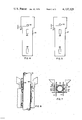
- FIG. 4 illustrates one design of weld guide used in carrying out the welding process
- FIG. 5 illustrates a substantially identical weld guide except for the position of a electrode opening therein
- FIG. 6 is a plan view showing how the weld guide of FIG. 4 fits into a fuel assembly grid
- FIG. 7 is a side view of the parts illustrating how the electrode extends through the weld guide and into contact with tabs on opposite sides of a control rod guide thimble.
- FIG. 1 a conventional fuel assembly grid 10 which includes multiple interleaved plates or grid straps 12 arranged to form egg crate openings or cells 14 through which multiple fuel rods 16 and control rod guide thimbles 18 axially extend.
- the side of straps 12 forming each cell includes a pair of dimples 20 on two adjacent straps while the remaining two adjacent sides includes springs 22, the arrangement being such that according to well known designs, each fuel rod is supported by the dimples and springs.
- each control rod guide thimble is of greater diameter than a fuel rod
- the plates or straps are designed such that neither dimple nor springs will project into the cell into which a control rod guide thimble is inserted.
- the control rod guide thimble fully occupies the cell area formed by the interleaved grid straps. Dimples 20 and springs 22 project into the adjacent cells but not into the cell containing a control rod guide thimble.
- the grid straps forming the cell in which the control rod guide thimble axially extend includes a tab 24 which is welded to opposite sides of the guide thimble thus providing a firm structure which is not displaced by axially directed hydraulic forces.
- this grid design has shown this grid design to be efficient, reliable and safe in operation.
- the major problem encountered during the manufacturing process is that of accurately welding the grid strap tabs 24 to the outer surface of the control rod guide thimble.
- the electrodes 25 of a weld gun are accurately located in position relative to the tabs by a weld guide 26 which is removable after each use.
- Two separate weld guides of the same design are used.
- the first weld guide 26 illustrated in FIGS. 2 and 4 is of T-shaped configuration and includes a pair of openings 28 of a size to accept dimples 20 which project outwardly into the cell which is adjacent the cell holding a control rod guide thimble.
- the weld guide also includes a circular opening 30 of a size sufficient to accept an electrode on the welding gun.
- the electrode 25' on the other side of the gun also is correctly aligned with the grid tab on that side.
- the gun is then energized to provide a spot weld in a precise location on the tab and control rod guide thimble.
- a second weld guide 27 is used to accurately locate the second spot weld.
- the second weld guide is identical to the weld guide of FIG. 4 except that distance b, the location of opening 32 from the bottom 34 of the T, is greater than distance a in FIG. 4. Therefore, when weld guide 26 is removed from its position on the grid after the first spot weld is made, and weld guide 27 inserted in its place, the opening 32 will appear a greater distance outwardly on the tab. When the electrode is placed in opening 32 and the second spot weld made, it will appear a greater distance outwardly on the tab. Each tab then contains two spot welds.
- FIG. 7 shows the relative position of grid plates, weld guide and control rod guide thimble and electrodes immediately at the time of welding.
Landscapes
- Engineering & Computer Science (AREA)
- Physics & Mathematics (AREA)
- Mechanical Engineering (AREA)
- Plasma & Fusion (AREA)
- Optics & Photonics (AREA)
- General Engineering & Computer Science (AREA)
- High Energy & Nuclear Physics (AREA)
- Butt Welding And Welding Of Specific Article (AREA)
Priority Applications (4)
| Application Number | Priority Date | Filing Date | Title |
|---|---|---|---|
| US05/741,436 US4137125A (en) | 1976-11-12 | 1976-11-12 | Method of welding nuclear reactor fuel assemblies |
| ES463935A ES463935A1 (es) | 1976-11-12 | 1977-11-08 | Un metodo perfeccionamiento de soldar mangaitos de guia de barra de control de reactor nucleares. |
| JP13415677A JPS5360478A (en) | 1976-11-12 | 1977-11-10 | Method of welding control rod guide column to fuel assembly lattice |
| IT29524/77A IT1087886B (it) | 1976-11-12 | 1977-11-10 | Metodo per saldare bussole di guida di barre di regolazione ad una griglia di complesso di combustibile. |
Applications Claiming Priority (1)
| Application Number | Priority Date | Filing Date | Title |
|---|---|---|---|
| US05/741,436 US4137125A (en) | 1976-11-12 | 1976-11-12 | Method of welding nuclear reactor fuel assemblies |
Publications (1)
| Publication Number | Publication Date |
|---|---|
| US4137125A true US4137125A (en) | 1979-01-30 |
Family
ID=24980712
Family Applications (1)
| Application Number | Title | Priority Date | Filing Date |
|---|---|---|---|
| US05/741,436 Expired - Lifetime US4137125A (en) | 1976-11-12 | 1976-11-12 | Method of welding nuclear reactor fuel assemblies |
Country Status (4)
| Country | Link |
|---|---|
| US (1) | US4137125A (it) |
| JP (1) | JPS5360478A (it) |
| ES (1) | ES463935A1 (it) |
| IT (1) | IT1087886B (it) |
Cited By (20)
| Publication number | Priority date | Publication date | Assignee | Title |
|---|---|---|---|---|
| FR2431163A1 (fr) * | 1978-07-14 | 1980-02-08 | Westinghouse Electric Corp | Grille d'assemblage combustible de reacteur nucleaire |
| US4381854A (en) * | 1980-02-11 | 1983-05-03 | Bruner Harry E | Guide bar for cutting torch |
| FR2520149A1 (fr) * | 1982-01-20 | 1983-07-22 | Commissariat Energie Atomique | Grille d'espacement pour assemblage combustible de reacteur nucleaire comportant des points d'appui opposes deux a deux pratiques sur des lamelles deformables elastiquement |
| FR2531562A1 (fr) * | 1982-08-05 | 1984-02-10 | Westinghouse Electric Corp | Grille d'espacement pour elements combustibles nucleaires |
| FR2532462A1 (fr) * | 1982-09-01 | 1984-03-02 | Westinghouse Electric Corp | Grille a barreaux combustibles avec des manchons soudes dans des bandes encochees |
| EP0134920A1 (en) * | 1983-07-26 | 1985-03-27 | Westinghouse Electric Corporation | Welding fixture for nuclear reactor fuel assembly grid |
| FR2574177A1 (fr) * | 1984-11-30 | 1986-06-06 | Chausson Usines Sa | Dispositif pour le maintien temporaire d'une boite a eau sur la plaque collectrice d'un echangeur de chaleur |
| US4659541A (en) * | 1985-05-01 | 1987-04-21 | Westinghouse Electric Corp. | Nuclear fuel rod support grid with improved multiple dimple arrangement |
| US4820472A (en) * | 1981-07-14 | 1989-04-11 | Westinghouse Electric Corp. | Nuclear reactor spent fuel storage rack |
| US5488644A (en) * | 1994-07-13 | 1996-01-30 | General Electric Company | Spring assemblies for adjoining nuclear fuel rod containing ferrules and a spacer formed of the spring assemblies and ferrules |
| US5519747A (en) * | 1994-10-04 | 1996-05-21 | General Electric Company | Apparatus and methods for fabricating spacers for a nuclear fuel rod bundle |
| US5546437A (en) * | 1995-01-11 | 1996-08-13 | General Electric Company | Spacer for nuclear fuel rods |
| US5566217A (en) * | 1995-01-30 | 1996-10-15 | General Electric Company | Reduced height spacer for nuclear fuel rods |
| US5675621A (en) * | 1995-08-17 | 1997-10-07 | General Electric Company | Reduced height flat spring spacer for nuclear fuel rods |
| CZ301984B6 (cs) * | 2003-08-18 | 2010-08-25 | Otkrytoe Aktsionernoe Obschestvo "Tvel" | Palivový systém pro jaderný reaktor |
| WO2013158708A1 (en) * | 2012-04-17 | 2013-10-24 | Babcock & Wilcox Mpower, Inc. | Pulse arc welding of spacer grids to guide tubes |
| CN103753327A (zh) * | 2013-12-23 | 2014-04-30 | 柳州市永信机械配件制造有限公司 | 宽头定位板 |
| CN109935359A (zh) * | 2017-12-19 | 2019-06-25 | 中国原子能科学研究院 | 一种燃料组件骨架连接结构及燃料组件骨架 |
| US10759007B2 (en) * | 2013-03-14 | 2020-09-01 | Bwxt Mpower, Inc. | Spacer grid welding fixture |
| US20220392652A1 (en) * | 2019-11-13 | 2022-12-08 | Westinghouse Electric Sweden Ab | Tube Grid Cell |
Citations (9)
| Publication number | Priority date | Publication date | Assignee | Title |
|---|---|---|---|---|
| US2250845A (en) * | 1938-12-17 | 1941-07-29 | Ibm | Pattern controlled multiple drilling machine |
| US2451123A (en) * | 1944-11-29 | 1948-10-12 | H O Schultz Inc | Multiple drill template |
| US2464906A (en) * | 1947-03-31 | 1949-03-22 | Pullman Standard Car Mfg Co | Indexing device for welding machines |
| US2614198A (en) * | 1950-12-13 | 1952-10-14 | Austin Motor Co Ltd | Heat exchanger |
| US2931887A (en) * | 1956-10-01 | 1960-04-05 | Leist Karl | Tube arrangement |
| US3417477A (en) * | 1967-12-22 | 1968-12-24 | Allis Chalmers Mfg Co | Template for the gas cutting of holes |
| US3430028A (en) * | 1965-12-08 | 1969-02-25 | Gen Dynamics Corp | Welding station |
| US3562482A (en) * | 1968-07-16 | 1971-02-09 | Northern Electric Co | Self-aligning electrode tip holder |
| US3791466A (en) * | 1969-05-19 | 1974-02-12 | Westinghouse Electric Corp | Low parasitic capture fuel assembly structure |
Family Cites Families (1)
| Publication number | Priority date | Publication date | Assignee | Title |
|---|---|---|---|---|
| US3920516A (en) * | 1972-09-25 | 1975-11-18 | Westinghouse Electric Corp | Nuclear reactor fuel assembly arrangement |
-
1976
- 1976-11-12 US US05/741,436 patent/US4137125A/en not_active Expired - Lifetime
-
1977
- 1977-11-08 ES ES463935A patent/ES463935A1/es not_active Expired
- 1977-11-10 JP JP13415677A patent/JPS5360478A/ja active Pending
- 1977-11-10 IT IT29524/77A patent/IT1087886B/it active
Patent Citations (9)
| Publication number | Priority date | Publication date | Assignee | Title |
|---|---|---|---|---|
| US2250845A (en) * | 1938-12-17 | 1941-07-29 | Ibm | Pattern controlled multiple drilling machine |
| US2451123A (en) * | 1944-11-29 | 1948-10-12 | H O Schultz Inc | Multiple drill template |
| US2464906A (en) * | 1947-03-31 | 1949-03-22 | Pullman Standard Car Mfg Co | Indexing device for welding machines |
| US2614198A (en) * | 1950-12-13 | 1952-10-14 | Austin Motor Co Ltd | Heat exchanger |
| US2931887A (en) * | 1956-10-01 | 1960-04-05 | Leist Karl | Tube arrangement |
| US3430028A (en) * | 1965-12-08 | 1969-02-25 | Gen Dynamics Corp | Welding station |
| US3417477A (en) * | 1967-12-22 | 1968-12-24 | Allis Chalmers Mfg Co | Template for the gas cutting of holes |
| US3562482A (en) * | 1968-07-16 | 1971-02-09 | Northern Electric Co | Self-aligning electrode tip holder |
| US3791466A (en) * | 1969-05-19 | 1974-02-12 | Westinghouse Electric Corp | Low parasitic capture fuel assembly structure |
Cited By (29)
| Publication number | Priority date | Publication date | Assignee | Title |
|---|---|---|---|---|
| US4268356A (en) * | 1978-07-14 | 1981-05-19 | Westinghouse Electric Corp. | Nuclear reactor fuel assembly grid |
| FR2431163A1 (fr) * | 1978-07-14 | 1980-02-08 | Westinghouse Electric Corp | Grille d'assemblage combustible de reacteur nucleaire |
| US4381854A (en) * | 1980-02-11 | 1983-05-03 | Bruner Harry E | Guide bar for cutting torch |
| US4820472A (en) * | 1981-07-14 | 1989-04-11 | Westinghouse Electric Corp. | Nuclear reactor spent fuel storage rack |
| US4622204A (en) * | 1982-01-20 | 1986-11-11 | Commissariat A L'energie Atomique | Spacer grid for nuclear reactor fuel assembly |
| FR2520149A1 (fr) * | 1982-01-20 | 1983-07-22 | Commissariat Energie Atomique | Grille d'espacement pour assemblage combustible de reacteur nucleaire comportant des points d'appui opposes deux a deux pratiques sur des lamelles deformables elastiquement |
| EP0084481A3 (en) * | 1982-01-20 | 1983-08-03 | Commissariat A L'energie Atomique Etablissement De Caractere Scientifique Technique Et Industriel | Nuclear reactor fuel assembly spacer grid having opposing pointed supports situated on resilient lamellae |
| FR2531562A1 (fr) * | 1982-08-05 | 1984-02-10 | Westinghouse Electric Corp | Grille d'espacement pour elements combustibles nucleaires |
| EP0101241A3 (en) * | 1982-08-05 | 1984-05-30 | Westinghouse Electric Corporation | Nuclear fuel spacer grid |
| FR2532462A1 (fr) * | 1982-09-01 | 1984-03-02 | Westinghouse Electric Corp | Grille a barreaux combustibles avec des manchons soudes dans des bandes encochees |
| EP0103444A3 (en) * | 1982-09-01 | 1984-09-05 | Westinghouse Electric Corporation | Fuel grid with sleeves welded in notched grid straps |
| EP0134920A1 (en) * | 1983-07-26 | 1985-03-27 | Westinghouse Electric Corporation | Welding fixture for nuclear reactor fuel assembly grid |
| FR2574177A1 (fr) * | 1984-11-30 | 1986-06-06 | Chausson Usines Sa | Dispositif pour le maintien temporaire d'une boite a eau sur la plaque collectrice d'un echangeur de chaleur |
| US4659541A (en) * | 1985-05-01 | 1987-04-21 | Westinghouse Electric Corp. | Nuclear fuel rod support grid with improved multiple dimple arrangement |
| US5488644A (en) * | 1994-07-13 | 1996-01-30 | General Electric Company | Spring assemblies for adjoining nuclear fuel rod containing ferrules and a spacer formed of the spring assemblies and ferrules |
| US5519747A (en) * | 1994-10-04 | 1996-05-21 | General Electric Company | Apparatus and methods for fabricating spacers for a nuclear fuel rod bundle |
| US5546437A (en) * | 1995-01-11 | 1996-08-13 | General Electric Company | Spacer for nuclear fuel rods |
| US5566217A (en) * | 1995-01-30 | 1996-10-15 | General Electric Company | Reduced height spacer for nuclear fuel rods |
| US5675621A (en) * | 1995-08-17 | 1997-10-07 | General Electric Company | Reduced height flat spring spacer for nuclear fuel rods |
| CZ301984B6 (cs) * | 2003-08-18 | 2010-08-25 | Otkrytoe Aktsionernoe Obschestvo "Tvel" | Palivový systém pro jaderný reaktor |
| US20130301791A1 (en) * | 2012-04-17 | 2013-11-14 | Babcock & Wilcox Mpower Inc | Pulse arc welding of spacer grids to guide tubes |
| WO2013158708A1 (en) * | 2012-04-17 | 2013-10-24 | Babcock & Wilcox Mpower, Inc. | Pulse arc welding of spacer grids to guide tubes |
| US10759007B2 (en) * | 2013-03-14 | 2020-09-01 | Bwxt Mpower, Inc. | Spacer grid welding fixture |
| US11338398B2 (en) | 2013-03-14 | 2022-05-24 | Bwxt Mpower, Inc. | Spacer grid welding fixture |
| US11738416B2 (en) | 2013-03-14 | 2023-08-29 | Bwxt Mpower, Inc. | Spacer grid welding fixture |
| CN103753327A (zh) * | 2013-12-23 | 2014-04-30 | 柳州市永信机械配件制造有限公司 | 宽头定位板 |
| CN109935359A (zh) * | 2017-12-19 | 2019-06-25 | 中国原子能科学研究院 | 一种燃料组件骨架连接结构及燃料组件骨架 |
| US20220392652A1 (en) * | 2019-11-13 | 2022-12-08 | Westinghouse Electric Sweden Ab | Tube Grid Cell |
| US12148540B2 (en) * | 2019-11-13 | 2024-11-19 | Westinghouse Electric Sweden Ab | Tube grid cell for a nuclear fuel bundle |
Also Published As
| Publication number | Publication date |
|---|---|
| ES463935A1 (es) | 1979-04-16 |
| IT1087886B (it) | 1985-06-04 |
| JPS5360478A (en) | 1978-05-31 |
Similar Documents
| Publication | Publication Date | Title |
|---|---|---|
| US4137125A (en) | Method of welding nuclear reactor fuel assemblies | |
| US6120564A (en) | Connection method for batteries | |
| US3920515A (en) | Fuel assembly for a nuclear reactor | |
| US3255091A (en) | Fuel arrangement for a nuclear reactor | |
| EP0154229B1 (en) | improved fuel rod assembly for a nuclear reactor | |
| DE202020005939U1 (de) | Knopfzelle und elektronische Vorrichtung | |
| KR910004192B1 (ko) | 홈이 파인 그리드 스트랩에서 용접된 슬리브를 갖는 연료그리드 | |
| KR20250012705A (ko) | 원통형 배터리 셀, 그리고 이를 포함하는 배터리 팩 및 자동차 | |
| US4684503A (en) | Reconstitutable nuclear reactor fuel assembly with unitary removable top nozzle subassembly | |
| EP4383442A1 (en) | Welding jig | |
| US4101752A (en) | Process for welding corner cells in fuel assembly grids | |
| JP2004534950A (ja) | 原子炉グリッド用の一体的締着型スペーサ及び関連の方法 | |
| JP4168491B2 (ja) | 密閉電池の製造法 | |
| US4556776A (en) | Welding fixture for nuclear reactor fuel assembly grid | |
| KR101640942B1 (ko) | 원자로용 핵연료 집합체 | |
| CN220073539U (zh) | 顶盖预点焊装置及电芯入壳设备 | |
| JPS6195782A (ja) | スタツド溶接方法 | |
| CN115351422B (zh) | 方壳电芯激光焊接设备及其辅助夹具 | |
| CN218731171U (zh) | 一种方形电芯顶盖密封焊接的保护装置 | |
| JPS6157887A (ja) | 中性子源位置決め装置 | |
| US3688079A (en) | Welding nozzle | |
| CN116851897B (zh) | 顶盖预点焊装置及电芯入壳设备 | |
| CN222095088U (zh) | 焊接定位板 | |
| US7149273B2 (en) | Method of fabricating a nuclear reactor fuel assembly grid | |
| JPS5941569Y2 (ja) | 蓄電池の極柱構造 |