US4109727A - Dual-seal sprinkler system - Google Patents
Dual-seal sprinkler system Download PDFInfo
- Publication number
- US4109727A US4109727A US05/718,401 US71840176A US4109727A US 4109727 A US4109727 A US 4109727A US 71840176 A US71840176 A US 71840176A US 4109727 A US4109727 A US 4109727A
- Authority
- US
- United States
- Prior art keywords
- closure
- sealing member
- seat
- seal
- disposed
- Prior art date
- Legal status (The legal status is an assumption and is not a legal conclusion. Google has not performed a legal analysis and makes no representation as to the accuracy of the status listed.)
- Expired - Lifetime
Links
- 238000007789 sealing Methods 0.000 claims abstract description 73
- 239000000463 material Substances 0.000 claims description 24
- 239000012530 fluid Substances 0.000 claims description 20
- 239000012528 membrane Substances 0.000 claims description 11
- 239000013013 elastic material Substances 0.000 claims description 5
- 230000006866 deterioration Effects 0.000 claims description 3
- 230000002093 peripheral effect Effects 0.000 claims 2
- 239000003708 ampul Substances 0.000 description 11
- 239000011521 glass Substances 0.000 description 11
- 230000002411 adverse Effects 0.000 description 8
- 239000002184 metal Substances 0.000 description 8
- 239000000126 substance Substances 0.000 description 8
- XLYOFNOQVPJJNP-UHFFFAOYSA-N water Substances O XLYOFNOQVPJJNP-UHFFFAOYSA-N 0.000 description 4
- -1 fluoro-elastimers Substances 0.000 description 3
- 239000007788 liquid Substances 0.000 description 3
- 229920001343 polytetrafluoroethylene Polymers 0.000 description 2
- 230000004913 activation Effects 0.000 description 1
- 230000004888 barrier function Effects 0.000 description 1
- 230000006835 compression Effects 0.000 description 1
- 238000007906 compression Methods 0.000 description 1
- 230000002939 deleterious effect Effects 0.000 description 1
- 238000001514 detection method Methods 0.000 description 1
- 230000002542 deteriorative effect Effects 0.000 description 1
- 230000000694 effects Effects 0.000 description 1
- 230000002349 favourable effect Effects 0.000 description 1
- 230000005923 long-lasting effect Effects 0.000 description 1
- 239000000155 melt Substances 0.000 description 1
- 239000000203 mixture Substances 0.000 description 1
- 238000012856 packing Methods 0.000 description 1
- 239000002244 precipitate Substances 0.000 description 1
- 230000002035 prolonged effect Effects 0.000 description 1
- 239000003566 sealing material Substances 0.000 description 1
- 229920002379 silicone rubber Polymers 0.000 description 1
- 239000004945 silicone rubber Substances 0.000 description 1
Images

Classifications
-
- A—HUMAN NECESSITIES
- A62—LIFE-SAVING; FIRE-FIGHTING
- A62C—FIRE-FIGHTING
- A62C37/00—Control of fire-fighting equipment
- A62C37/08—Control of fire-fighting equipment comprising an outlet device containing a sensor, or itself being the sensor, i.e. self-contained sprinklers
-
- A—HUMAN NECESSITIES
- A62—LIFE-SAVING; FIRE-FIGHTING
- A62C—FIRE-FIGHTING
- A62C37/00—Control of fire-fighting equipment
- A62C37/08—Control of fire-fighting equipment comprising an outlet device containing a sensor, or itself being the sensor, i.e. self-contained sprinklers
- A62C37/10—Releasing means, e.g. electrically released
- A62C37/11—Releasing means, e.g. electrically released heat-sensitive
- A62C37/12—Releasing means, e.g. electrically released heat-sensitive with fusible links
-
- Y—GENERAL TAGGING OF NEW TECHNOLOGICAL DEVELOPMENTS; GENERAL TAGGING OF CROSS-SECTIONAL TECHNOLOGIES SPANNING OVER SEVERAL SECTIONS OF THE IPC; TECHNICAL SUBJECTS COVERED BY FORMER USPC CROSS-REFERENCE ART COLLECTIONS [XRACs] AND DIGESTS
- Y10—TECHNICAL SUBJECTS COVERED BY FORMER USPC
- Y10S—TECHNICAL SUBJECTS COVERED BY FORMER USPC CROSS-REFERENCE ART COLLECTIONS [XRACs] AND DIGESTS
- Y10S277/00—Seal for a joint or juncture
- Y10S277/917—Seal including frangible feature
Definitions
- This invention relates to a fire extinguishing sprinkler activated by a temperature responsive destructable or yieldable detector, which maintains a closure in position to contain a fire extinguishing fluid, and in particular to an improved means of providing a long-lasting seal to contain the fluid.
- a sprinkler comprising a frame with a passage terminating at a seat and having a closure disposed across the passage, a seal having a pressure-impacted side and an ambient pressure side is disposed between the closure and the seat, means attached to another portion of the frame to hold the closure against the seal thus to prevent fluid on the pressure side from passing through the passage, and is adapted to release the closure and the seal when the surrounding temperature has been elevated to some predetermined level, and a seal comprising a first sealing member disposed against the seat and a second sealing member disposed between the closure and the first sealing member, the second sealing member pressing the first sealing member against the seat and being covered by the first sealing member on the pressure-impacted side.
- FIG. 1 is a sectional view of an embodiment of the invention, showing the destructable glass ampoule holding the closure in position with the two member seal positioned against the seat.
- FIG. 2 shows an alternative to the embodiment shown in FIG. 1 with the addition of a clamping ring on the closure to secure the first member of the seal to the closure.
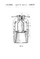
- FIG. 3 is a sectional view of a second alternative embodiment of the invention, showing a fusible thermal detector in the position of the glass ampoule of FIG. 1, along with a change in the geometry of the closure and first seal member.
- an adjustable screw 3 which holds a glass ampoule 4 in position.
- the glass ampoule is in compressional contact between a metallic closure 7 and the adjustable screw 3.
- thermally responsive devices may be used to keep the metalic closure 7 against the seat of the frame and yet will respond by releasing the closure at an elevated temperature.
- a thin-walled glass ampoule filled with an expandable liquid has been chosen as the thermally responsive element. Threaded screw 3 may be adjusted to position the glass ampoule 4 against closure 7 and may be advanced to provide the necessary pressure to maintain the integrity of the seal to prevent any leaking.
- glass ampoule 4 comprises the means which is disposed between the frame and the closure to hold the closure in position.
- Closure 7 may consist of a formed metal plate or other suitable material, as shown in FIG. 1 to provide closure against the seat on the pressure-impacted side of the passage.
- the seal is positioned to contact the frame at the shoulder portion of the seat as shown in FIG. 1.
- the seal consists of two members: as illustrated, a first member 8 is a thin imperforate membrane of plastic sheet-like film material impervious to the deteriorating effects of the fluid in the passage 5.
- Membrane 8 is in contact with closure 7 and in direct contact with the seat shoulder portion of the frame.
- the second sealing member 6 comprises an elastic material in contact with the first sealing material and held in position by a flange portion of the metal closure 7. In sequence metal closure 7 contacts the second sealing member 6, which contacts the first sealing member 8, which contacts with the valve seat, thus providing the closure.
- the problem is to provide a seal for the sprinkler system which will not disintegrate over a long period of time nor under adverse physical and chemical conditions.
- This problem is resolved by the present invention by providing a seal consisting of two members.
- the first member is shown in the form of an annular ring, although it may be appreciated that many variations in geometry will suffice, which is in direct contact with the fire extinguishing fluid.
- This first member is in contact with metal closure 7 and extends to and rests on the shoulder of the seat of frame 1.
- the material is chosen so as to be impervious to adverse physical and chemical conditions in the pressure impacted region. An example of such material would be polytetrafluorethylene.
- metal closure 7 can have a flange which is vented by a series of holes or slots open to the ambient environment if no chemical attack on the material is expected.
- the glass ampoule 4, or fusible temperature detector 4a as shown in subsequent figures, is destroyed through the effect of the heat.
- parts numbered 6, 7 and 8 comprising the metal closure and the two member seal, are detached from the seat of frame 1 and the extinguishing fluid or gas mixture emerges from the passage without hindrance. The emerging fluid is then directed by distribution plate 2 to extinguish the fire.
- the two part sealing member provides an adequate leak-proof seal with the second sealing member being protected from the adverse physical and chemical conditions of the pressure impacted region.
- the interstitial space defined by and between the closure, first sealing member and second sealing member may also be filled with an inert fluid.
- FIG. 2 shows an alternative embodiment having a different geometric arrangement of the closure and sealing elements shown in FIG. 1.
- Closure 7 is shown to have a circular cross sectional flange such as might be appropriate for the use of an O-ring as the second sealing member 6.
- the first sealing member 8 is held in position as before but with the addition of a clamping ring 9 provided to retain the first closing member 8 in position against closure 7. It may be appreciated that several variations in geometry and arrangement of the elements comprising the preferred embodiment may be made without affecting the intended scope of the invention.
- FIG. 3 shows an additional preferred embodiment.
- the liquid filled glass ampoule 4 is now been replaced by a fusable thermal detector 4a.
- the fusable thermal detector is held in compression between adjustable screw 3 and closure 7. With elevated temperature the material in fusable detector 4a melts thus allowing the pressure on the pressure impact side of the passageway to disengage the closure and seal and allow free passage of the fire extinguishing fluid.
- both closure 7 and first sealing member 8 have different shapes than in FIG. 1.
- metallic closure 7 is disc shaped but with the original flange design to provide a containment for second sealing member 6.
- first sealing member 8 is made in the form of a disc to cover the entire passageway and still provide protection for the second sealing member, which is again shown in the form of an annular ring. In operation all of the parts function as discribed earlier with similarly reference numbered parts providing identical function.
Landscapes
- Health & Medical Sciences (AREA)
- Public Health (AREA)
- Business, Economics & Management (AREA)
- Emergency Management (AREA)
- Fire-Extinguishing By Fire Departments, And Fire-Extinguishing Equipment And Control Thereof (AREA)
Abstract
A sprinkler comprising a frame formed at one portion with a passage terminating at a seat, a closure disposed across the passage adjacent the seat, a seal having a pressure-impacted side and another side exposed to ambient pressure and being disposed between the closure and the seat, and a heat sensitive rupturable part disposed between another portion of the frame and the closure so as to hold the closure so disposed when the rupturable part is at ambient temperature and adapted to release the closure and the seal when the part is at elevated temperature, wherein the seal comprises a first sealing member disposed against the seat and a second sealing member disposed between a portion of the closure and the first sealing member, the second sealing member pressing the first sealing member against the seat and being covered by the first sealing member on the pressure-impacted side.
Description
Priority is claimed under 356 U.S.C. 119 for an application filed in the Federal Republic of Germany, Ser. No. P 25 39 703.9, Sept. 6, 1975.
1. Field of the Invention
This invention relates to a fire extinguishing sprinkler activated by a temperature responsive destructable or yieldable detector, which maintains a closure in position to contain a fire extinguishing fluid, and in particular to an improved means of providing a long-lasting seal to contain the fluid.
2. Prior Art
Many attempts have already been made to provide permanent seals for sprinklers which are activated by temperature responsive destructable or yieldable devices. Generally, elastic materials have been used to provide sealings or packings, since these materials possess the favorable physical characteristics to provide a good seal. However, the normal temperature range of operation for such sprinklers is from 50° to 250° C. (112°-482° F.) and since not only water but also other extinguishing fluids may be used, such seals encounter a variety of chemical conditions. In addition, sprinkler systems when installed must remain operational for a number of years. And it has been observed that even the best elastic materials tend to disintegrate or loose their proper sealing qualities with time. Users of sprinklers find such leaks intolerable since damage to equipment can occur. Moreover, the adverse physical or chemical conditions can accelerate the deleterious effects so that proper sealing can no longer be achieved.
Many known materials of the prior art exhibit the loss of their sealing qualities by becoming tacky so that they would tend to stick to the seat and thus prevent the desired activation of the sprinkler at a time when it would be called on to function. Therefore many materials, after having been exposed to adverse temperature and chemical conditions, cannot provide the necessary disengagement when the predetermined temperature is reached and thus such materials may precipitate a possible failure of the sprinkler.
The choice of even very expensive materials such as fluoro-elastimers, silicone rubber, and the like, does not eliminate these problems since even these materials are not impervious to water or steam for prolonged periods of time, especially when exposed to higher temperatures. Sprinkler seals which contain these materials in contact with water or moist air under pressure at higher temperatures exhibit speeded deterioration.
It is an object of this invention to provide a sprinkler which is activated at a predetermined temperature and includes an improved seal to prevent leakage of a high pressure fire extinguishing fluid.
It is an additional object of this invention to provide a fire extinguishing sprinkler system seal which will not deteriorate under prolonged exposure to adverse physical and chemical conditions yet remain elastic to allow proper disengagement when the sprinkler is activated.
These and other objects, features, and advantages of this invention may be attained in a sprinkler comprising a frame with a passage terminating at a seat and having a closure disposed across the passage, a seal having a pressure-impacted side and an ambient pressure side is disposed between the closure and the seat, means attached to another portion of the frame to hold the closure against the seal thus to prevent fluid on the pressure side from passing through the passage, and is adapted to release the closure and the seal when the surrounding temperature has been elevated to some predetermined level, and a seal comprising a first sealing member disposed against the seat and a second sealing member disposed between the closure and the first sealing member, the second sealing member pressing the first sealing member against the seat and being covered by the first sealing member on the pressure-impacted side.
FIG. 1 is a sectional view of an embodiment of the invention, showing the destructable glass ampoule holding the closure in position with the two member seal positioned against the seat.
FIG. 2 shows an alternative to the embodiment shown in FIG. 1 with the addition of a clamping ring on the closure to secure the first member of the seal to the closure.
FIG. 3 is a sectional view of a second alternative embodiment of the invention, showing a fusible thermal detector in the position of the glass ampoule of FIG. 1, along with a change in the geometry of the closure and first seal member.
FIG. 1 shows a cross sectional view of a sprinkler head body which incorporates the invention. The sprinkler head body comprises a frame 1 which has a passage 5 terminating at a seat. The seat end of the frame is threaded to allow screw mounting to a source of fire extinguishing fluid. Passage or region 5 represents the pressure impacted side of the sprinkler and defines that region containing a fluid, moist air under pressure or a gas for extinguishing a fire. On the ambient side of the sprinkler, there is included a distribution plate 2 for directing the flow of emerging water or other fire extinguishing fluid in a desired manner. This is normally made of metal, attached to frame 1, and consists of an array of petals or some other geometric design to achieve the proper distribution.
Also on the ambient side of the frame is an adjustable screw 3, which holds a glass ampoule 4 in position. The glass ampoule is in compressional contact between a metallic closure 7 and the adjustable screw 3. It may be appreciated that several forms of thermally responsive devices may be used to keep the metalic closure 7 against the seat of the frame and yet will respond by releasing the closure at an elevated temperature. In the preferred embodiment, a thin-walled glass ampoule filled with an expandable liquid has been chosen as the thermally responsive element. Threaded screw 3 may be adjusted to position the glass ampoule 4 against closure 7 and may be advanced to provide the necessary pressure to maintain the integrity of the seal to prevent any leaking. As the temperature is elevated, the liquid contained in glass ampoule 4 expands causing the glass-envelope to break, thus releasing the closure and allowing the fire extinguishing fluid to flow through the passage. In the preferred embodiment, glass ampoule 4 comprises the means which is disposed between the frame and the closure to hold the closure in position.
The problem is to provide a seal for the sprinkler system which will not disintegrate over a long period of time nor under adverse physical and chemical conditions. This problem is resolved by the present invention by providing a seal consisting of two members. The first member is shown in the form of an annular ring, although it may be appreciated that many variations in geometry will suffice, which is in direct contact with the fire extinguishing fluid. This first member is in contact with metal closure 7 and extends to and rests on the shoulder of the seat of frame 1. The material is chosen so as to be impervious to adverse physical and chemical conditions in the pressure impacted region. An example of such material would be polytetrafluorethylene. It is well known, however, that polytetrafluorethylene exhibits the phenomenon of cold creep and therefore this material by itself cannot provide an adequate seal. The second member of the seal is protected against the pressure impacted side by the first member and is held in position by the flange of metal closure 7. Through the additional application of the first sealing member 8 which is impervious to the adverse conditions, the second sealing member 6 is protected effectively against such conditions. This protection can be assured for long periods of time extending into years. On the ambiant side, the sealing member 6 retains its elastic qualities so that the advantages of the choice of the ordinary elastic materials may be realized. For example, the normal O-ring type sealing may be utilized in this case since the accelerated deterioration of the material due to the adverse conditions will no longer occur. Slight irregularities in the area of the valve seat can be ignored because both sealing members are deformable and the pressure of the closure is transferred to the seal to provide a secure fluid barrier.
As shown the second sealing member is completely covered from the ambient conditions. As an alternative design, metal closure 7 can have a flange which is vented by a series of holes or slots open to the ambient environment if no chemical attack on the material is expected. In operation at an elevated temperature the glass ampoule 4, or fusible temperature detector 4a as shown in subsequent figures, is destroyed through the effect of the heat. At this temperature parts numbered 6, 7 and 8, comprising the metal closure and the two member seal, are detached from the seat of frame 1 and the extinguishing fluid or gas mixture emerges from the passage without hindrance. The emerging fluid is then directed by distribution plate 2 to extinguish the fire. However, as long as the glass ampoule or temperature detection device is held in place, the two part sealing member provides an adequate leak-proof seal with the second sealing member being protected from the adverse physical and chemical conditions of the pressure impacted region. In an advantageous manner the interstitial space defined by and between the closure, first sealing member and second sealing member may also be filled with an inert fluid.
In subsequent figures identical reference numbers refer to identically functioning parts or devices, although some alternative design variations may be incorporated.
FIG. 2 shows an alternative embodiment having a different geometric arrangement of the closure and sealing elements shown in FIG. 1. Closure 7 is shown to have a circular cross sectional flange such as might be appropriate for the use of an O-ring as the second sealing member 6. The first sealing member 8 is held in position as before but with the addition of a clamping ring 9 provided to retain the first closing member 8 in position against closure 7. It may be appreciated that several variations in geometry and arrangement of the elements comprising the preferred embodiment may be made without affecting the intended scope of the invention.
FIG. 3 shows an additional preferred embodiment. The liquid filled glass ampoule 4 is now been replaced by a fusable thermal detector 4a. In this case, the fusable thermal detector is held in compression between adjustable screw 3 and closure 7. With elevated temperature the material in fusable detector 4a melts thus allowing the pressure on the pressure impact side of the passageway to disengage the closure and seal and allow free passage of the fire extinguishing fluid.
In FIG. 3 both closure 7 and first sealing member 8 have different shapes than in FIG. 1. For this embodiment metallic closure 7 is disc shaped but with the original flange design to provide a containment for second sealing member 6. Correspondingly, first sealing member 8 is made in the form of a disc to cover the entire passageway and still provide protection for the second sealing member, which is again shown in the form of an annular ring. In operation all of the parts function as discribed earlier with similarly reference numbered parts providing identical function.
Claims (7)
1. In a sprinkler comprising a frame formed at one portion with a fluid passage terminating at an annular seat, a closure disposed across said passage adjacent said seat, an annular seal having a pressure-impacted side and another side exposed to ambient pressure and being disposed between said closure and said seat, and means disposed between another portion of said frame and said closure so as to hold said closure with said seal when said means is at ambient temperature and adapted to release said closure and said seal when said means is at elevated temperature, an improvement wherein said seal comprises a sealing membrane of deformable sheet-like film material and having its periphery lying against said seat and also having an annular portion adjacent the periphery trasversing a portion of the passage and lying against the closure, and a compressibly elastic sealing ring disposed between a portion of said closure and the periphery of said sealing membrane, the closure bearing against said elastic sealing ring which resiliently presses the periphery of said annular sealing membrane against said seat to require the film material of the membrane to conform to the contour of the seat and seal thereagainst, said sealing membrane forming the pressure-impacted side of the seal and the annular portion of the membrane also traversing the elastic sealing ring and isolating the ring from the passage and the fluid therein.
2. The improvement of claim 1 wherein said first sealing membrane is formed from an annulus of plastic material.
3. The improvement of claim 1 wherein said sealing membrane is formed from a disc of plastic material.
4. The improvement of claim 1 wherein said closure, sealing membrane, and said sealing ring define an interstitial space filled with inert fluid.
5. In a sprinkler comprising a frame formed at one portion with a passage terminating at a seat, a closure disposed across said passage adjacent said seat, a seal having a pressure-impacted side and another side exposed to ambient pressure and being disposed between said closure and said seat, and means disposed between another portion of said frame and said closure so as to hold said closure with said seal and when said means is at ambient temperature and adapted to release said closure and said seal when said means is at elevated temperature, an improvement wherein said seal comprises a first sealing member of deformable sheet-like material and disposed against said seat and a second elastic sealing member disposed between a portion of said closure and said first sealing member, said second sealing member resiliently pressing said first sealing member against said seat and being covered by said first sealing member on the pressure-impacted side, and a clamp being mounted to hold said first sealing member on said closure.
6. In a sprinkler comprising a frame formed at one portion with a passage terminating at a seat, a closure disposed across said passage adjacent said seat, a seal having a pressure-impacted side and another side exposed to ambient pressure and being disposed between said closure and said seat, and means disposed between another portion of said frame and said closure so as to hold said closure with said seal when said means is at ambient temperature and adapted to release said closure and said seal when said means is at elevated temperature, an improvement wherein said seal comprises a first sealing member of deformable sheet-like material and disposed against said seat and a second elastic sealing member disposed between a portion of said closure and said first sealing member, said second sealing member resiliently pressing said first sealing member against said seat and being covered by said first sealing member on the pressure-impacted side, said second annular member being a ring formed of elastic material, said first sealing member being formed of an annulus of plastic material, and the closure having a grooved annular flange confining the second elastic sealing member from ambient conditions to minimize the deterioration thereof.
7. In a sprinkler comprising a frame formed at one portion with a passage terminating at a seat, a closure disposed across said passage adjacent said seat, a seal having a pressure-impacted side and another side exposed to ambient pressure and being disposed between said closure and said seat, and means disposed between another portion of said frame and said closure so as to hold said closure with said seal when said means is at ambient temperature and adapted to release said closure and said seal when said means is at elevated temperature, an improvement wherein said seal comprises a first sealing member of deformable sheet-like material and disposed against said seat and a second elastic sealing member disposed between a portion of said closure and said first sealing member, said second sealing member resiliently pressing said first sealing member against said seat and being covered by said first sealing member on the pressure-impacted side, said first sealing member being formed from an annulus of plastic material, the first sealing member having an inner peripheral portion engaging the closure at the pressure-impacted side to isolate the second sealing member from the sprinkler fluid in the passage, and the closure having an annular, outwardly facing surface adjacent the second sealing member, and a clamping ring embracing the closure and the inner peripheral portion of the first sealing member.
Applications Claiming Priority (2)
| Application Number | Priority Date | Filing Date | Title |
|---|---|---|---|
| DE2539703A DE2539703C2 (en) | 1975-09-06 | 1975-09-06 | Fire extinguisher head for automatic fire extinguishing systems |
| DE2539703 | 1975-09-06 |
Publications (1)
| Publication Number | Publication Date |
|---|---|
| US4109727A true US4109727A (en) | 1978-08-29 |
Family
ID=5955770
Family Applications (1)
| Application Number | Title | Priority Date | Filing Date |
|---|---|---|---|
| US05/718,401 Expired - Lifetime US4109727A (en) | 1975-09-06 | 1976-08-30 | Dual-seal sprinkler system |
Country Status (2)
| Country | Link |
|---|---|
| US (1) | US4109727A (en) |
| DE (1) | DE2539703C2 (en) |
Cited By (19)
| Publication number | Priority date | Publication date | Assignee | Title |
|---|---|---|---|---|
| WO1984002280A1 (en) * | 1982-12-07 | 1984-06-21 | Gw Sprinkler As | A sprinkler unit |
| US4611665A (en) * | 1983-09-27 | 1986-09-16 | Wormald International Limited | Sprinkler head valve means |
| US4796710A (en) * | 1985-09-09 | 1989-01-10 | Job Eduard J | Glass bulb for sprinkler heads |
| US4898246A (en) * | 1987-07-06 | 1990-02-06 | Total Walther Feuerschutz Gmbh | Quick release valve for sprinkler head |
| US5628367A (en) * | 1994-11-08 | 1997-05-13 | The Viking Corporation | Temperature sensitive sprinkler head with improved spring |
| US5826665A (en) * | 1994-11-08 | 1998-10-27 | Truax; Perin E. | Sprinkler head with stamped trigger-mounting elements |
| US6502643B1 (en) | 1997-03-07 | 2003-01-07 | Central Sprinkler Company | Low pressure, early suppression fast response sprinklers |
| US20060243460A1 (en) * | 2005-04-27 | 2006-11-02 | Geyer James E Jr | Fire extinguisher |
| US20080217572A1 (en) * | 2005-07-22 | 2008-09-11 | Job Lizenz Gmbh & Co. Kg | Safety Valve for a Compressed Gas Container |
| US20090242218A1 (en) * | 2008-03-13 | 2009-10-01 | Van Schoor Marthinus Cornelius | Method and apparatus for thermally activated sprinklers |
| US20090294140A1 (en) * | 2008-06-02 | 2009-12-03 | The Viking Corporation | Fire Protection Sprinkler With Plastic Pip Cap |
| USD694855S1 (en) | 2012-12-12 | 2013-12-03 | The Viking Corporation | Pip cap assembly for a fire protection sprinkler |
| WO2013117907A3 (en) * | 2012-02-07 | 2014-03-27 | Marioff Corporation | Water mist fire suppression sprinkler with a polymer seal |
| US9265981B2 (en) | 2012-12-12 | 2016-02-23 | The Viking Corporation | Pip cap assembly for a fire protection sprinkler |
| US9573007B2 (en) | 2013-03-15 | 2017-02-21 | Tyco Fire Products Lp | Fire protection sprinkler |
| USD781399S1 (en) * | 2015-10-08 | 2017-03-14 | Senju Sprinkler Co., Ltd. | Sprinkler head body |
| DE202017101700U1 (en) | 2017-03-23 | 2018-06-27 | Job Lizenz Gmbh & Co. Kg | Closing element for a thermal release device |
| WO2022040498A1 (en) | 2020-08-21 | 2022-02-24 | Engineered Corrosion Solutions, Llc | Nozzle plugs for a deluge fire protection system |
| US12214234B2 (en) | 2017-01-19 | 2025-02-04 | Victaulic Company | Direct coupling compatible sprinkler |
Families Citing this family (7)
| Publication number | Priority date | Publication date | Assignee | Title |
|---|---|---|---|---|
| DE3106110A1 (en) * | 1981-02-19 | 1982-09-02 | Georg Ing.(grad.) 8653 Mainleus Herold | Spraying system for improving the fire resistance of doors or the like in buildings in the event of a fire |
| DE3624939A1 (en) * | 1986-07-23 | 1988-01-28 | Verband Der Sachversicherer E | SPRINKLER / LOESCHDUESE FOR FIXED FIRE-FIGHTING SYSTEMS |
| DE3819749A1 (en) * | 1988-06-10 | 1989-12-14 | Verband Der Sachversicherer Ev | THERMAL RELEASE DEVICE FOR SPRINKLERS FOR FIXED FIRE EXTINGUISHING SYSTEMS |
| DE4417314C2 (en) * | 1994-05-18 | 1998-11-12 | Werner Lueddecke | Sprinkler nozzle |
| US5667017A (en) * | 1994-09-17 | 1997-09-16 | Awab Umformtechnik Gmbh & Co. Kg | Atomizer for generating water-mists in fire-fighting systems |
| DE102018125861B3 (en) | 2018-10-18 | 2019-12-19 | Job Lizenz Gmbh & Co. Kg | Process for monitoring the quality of extinguishing water in sprinkler systems and sprinkler head |
| CN112677162B (en) * | 2020-12-16 | 2025-09-12 | 苏州大学 | Magnetically controlled bionic robot and control method thereof |
Citations (29)
| Publication number | Priority date | Publication date | Assignee | Title |
|---|---|---|---|---|
| US793357A (en) * | 1904-08-15 | 1905-06-27 | Georg Diederici | Automatic sprinkler. |
| US793821A (en) * | 1904-10-11 | 1905-07-04 | James A Cass Jr | Fire-extinguisher. |
| US842725A (en) * | 1904-05-25 | 1907-01-29 | Gen Fire Extinguisher Co | Automatic sprinkler. |
| US1733701A (en) * | 1925-05-27 | 1929-10-29 | Taylor John | Automatic sprinkler or fire extinguisher |
| US1797919A (en) * | 1929-11-30 | 1931-03-24 | Gen Fire Extinguisher Co | Quartz bulb |
| US2085987A (en) * | 1935-03-27 | 1937-07-06 | Gen Fire Extinguisher Co | Method of assembling an automatic sprinkler |
| US2324170A (en) * | 1940-07-17 | 1943-07-13 | Univ Minnesota | Sprinkler head |
| US2378273A (en) * | 1943-02-04 | 1945-06-12 | Warren F Wilhelm | Fluid distributing mechanism |
| US2661805A (en) * | 1951-03-05 | 1953-12-08 | Lim Peter | Fire extinguisher sprinkler head |
| US2859061A (en) * | 1954-09-17 | 1958-11-04 | William P Reid | Composite sealing ring and method of making the same |
| US2893060A (en) * | 1955-01-12 | 1959-07-07 | Wills Pressure Filled Joint Ri | Joint rings |
| US3007528A (en) * | 1959-07-17 | 1961-11-07 | Star Sprinkler Corp | Dry pendant sprinklers |
| US3080000A (en) * | 1961-07-19 | 1963-03-05 | Star Sprinkler Corp | Dry pendant sprinklers |
| GB954967A (en) * | 1961-07-28 | 1964-04-08 | Heinz Martin Wittenburg | Improvements in or relating to sprinkler heads for automatic fire-extinguishing installations |
| US3171935A (en) * | 1961-12-29 | 1965-03-02 | Star Sprinkler Corp | Heat responsive device |
| FR1408571A (en) * | 1964-09-22 | 1965-08-13 | Jomos Feuerlosch Technik J G M | Device for extinguishing fire and preventing its spread by spraying and distributing an extinguishing liquid |
| US3273743A (en) * | 1963-05-17 | 1966-09-20 | Rubbarite Ltd | Sealing |
| US3385604A (en) * | 1965-09-09 | 1968-05-28 | Daniel Traufier | Resiliently compressible packing joints |
| GB1118526A (en) * | 1966-07-12 | 1968-07-03 | Angus George Co Ltd | Improvements in sprinklers for fixed fire installations |
| US3446286A (en) * | 1965-07-12 | 1969-05-27 | William E Kreidler | Automatic fire extinguisher |
| US3618814A (en) * | 1969-08-25 | 1971-11-09 | Adolph Nagroski | Rectangular tapered nestable waste can and cover |
| US3625289A (en) * | 1970-05-04 | 1971-12-07 | Star Sprinkler Corp Of Florida | Sprinkler |
| US3633676A (en) * | 1970-04-01 | 1972-01-11 | Star Sprinkler Corp Of Florida | Flush-type sprinkler |
| US3635370A (en) * | 1970-08-11 | 1972-01-18 | Sorvall Inc Ivan | Centrifuge tube closure assembly |
| US3714989A (en) * | 1971-06-07 | 1973-02-06 | Star Sprinkler Corp Of Florida | Flush type sprinkler |
| US3715700A (en) * | 1971-06-17 | 1973-02-06 | Star Sprinkler Corp Of Florida | Automatic heat detector |
| GB1349935A (en) * | 1970-09-16 | 1974-04-10 | Firemaster Extinguisher Ltd | Fire extinguishing apparatus |
| US3812915A (en) * | 1973-06-04 | 1974-05-28 | Factory Mutual Res Corp | Discharge head having constant force plug retaining member |
| US3874456A (en) * | 1972-09-12 | 1975-04-01 | Star Sprinkler Corp Of Florida | Sprinkler |
Family Cites Families (1)
| Publication number | Priority date | Publication date | Assignee | Title |
|---|---|---|---|---|
| GB552810A (en) * | 1941-09-17 | 1943-04-27 | Thomas Anthony Henshaw | Improvements in and relating to automatic sprinkler heads for fire extinguishers |
-
1975
- 1975-09-06 DE DE2539703A patent/DE2539703C2/en not_active Expired
-
1976
- 1976-08-30 US US05/718,401 patent/US4109727A/en not_active Expired - Lifetime
Patent Citations (30)
| Publication number | Priority date | Publication date | Assignee | Title |
|---|---|---|---|---|
| US842725A (en) * | 1904-05-25 | 1907-01-29 | Gen Fire Extinguisher Co | Automatic sprinkler. |
| US793357A (en) * | 1904-08-15 | 1905-06-27 | Georg Diederici | Automatic sprinkler. |
| US793821A (en) * | 1904-10-11 | 1905-07-04 | James A Cass Jr | Fire-extinguisher. |
| US1733701A (en) * | 1925-05-27 | 1929-10-29 | Taylor John | Automatic sprinkler or fire extinguisher |
| US1797919A (en) * | 1929-11-30 | 1931-03-24 | Gen Fire Extinguisher Co | Quartz bulb |
| US2085987A (en) * | 1935-03-27 | 1937-07-06 | Gen Fire Extinguisher Co | Method of assembling an automatic sprinkler |
| US2324170A (en) * | 1940-07-17 | 1943-07-13 | Univ Minnesota | Sprinkler head |
| US2378273A (en) * | 1943-02-04 | 1945-06-12 | Warren F Wilhelm | Fluid distributing mechanism |
| US2661805A (en) * | 1951-03-05 | 1953-12-08 | Lim Peter | Fire extinguisher sprinkler head |
| US2859061A (en) * | 1954-09-17 | 1958-11-04 | William P Reid | Composite sealing ring and method of making the same |
| US2893060A (en) * | 1955-01-12 | 1959-07-07 | Wills Pressure Filled Joint Ri | Joint rings |
| US3007528A (en) * | 1959-07-17 | 1961-11-07 | Star Sprinkler Corp | Dry pendant sprinklers |
| US3080000A (en) * | 1961-07-19 | 1963-03-05 | Star Sprinkler Corp | Dry pendant sprinklers |
| GB954967A (en) * | 1961-07-28 | 1964-04-08 | Heinz Martin Wittenburg | Improvements in or relating to sprinkler heads for automatic fire-extinguishing installations |
| US3253657A (en) * | 1961-07-28 | 1966-05-31 | Selbsttatige Feuerloschanlagen | Nozzle for automatic fire extinguishing devices |
| US3171935A (en) * | 1961-12-29 | 1965-03-02 | Star Sprinkler Corp | Heat responsive device |
| US3273743A (en) * | 1963-05-17 | 1966-09-20 | Rubbarite Ltd | Sealing |
| FR1408571A (en) * | 1964-09-22 | 1965-08-13 | Jomos Feuerlosch Technik J G M | Device for extinguishing fire and preventing its spread by spraying and distributing an extinguishing liquid |
| US3446286A (en) * | 1965-07-12 | 1969-05-27 | William E Kreidler | Automatic fire extinguisher |
| US3385604A (en) * | 1965-09-09 | 1968-05-28 | Daniel Traufier | Resiliently compressible packing joints |
| GB1118526A (en) * | 1966-07-12 | 1968-07-03 | Angus George Co Ltd | Improvements in sprinklers for fixed fire installations |
| US3618814A (en) * | 1969-08-25 | 1971-11-09 | Adolph Nagroski | Rectangular tapered nestable waste can and cover |
| US3633676A (en) * | 1970-04-01 | 1972-01-11 | Star Sprinkler Corp Of Florida | Flush-type sprinkler |
| US3625289A (en) * | 1970-05-04 | 1971-12-07 | Star Sprinkler Corp Of Florida | Sprinkler |
| US3635370A (en) * | 1970-08-11 | 1972-01-18 | Sorvall Inc Ivan | Centrifuge tube closure assembly |
| GB1349935A (en) * | 1970-09-16 | 1974-04-10 | Firemaster Extinguisher Ltd | Fire extinguishing apparatus |
| US3714989A (en) * | 1971-06-07 | 1973-02-06 | Star Sprinkler Corp Of Florida | Flush type sprinkler |
| US3715700A (en) * | 1971-06-17 | 1973-02-06 | Star Sprinkler Corp Of Florida | Automatic heat detector |
| US3874456A (en) * | 1972-09-12 | 1975-04-01 | Star Sprinkler Corp Of Florida | Sprinkler |
| US3812915A (en) * | 1973-06-04 | 1974-05-28 | Factory Mutual Res Corp | Discharge head having constant force plug retaining member |
Cited By (32)
| Publication number | Priority date | Publication date | Assignee | Title |
|---|---|---|---|---|
| WO1984002280A1 (en) * | 1982-12-07 | 1984-06-21 | Gw Sprinkler As | A sprinkler unit |
| GB2141337A (en) * | 1982-12-07 | 1984-12-19 | Gw Sprinkler As | A sprinkler unit |
| US4657085A (en) * | 1982-12-07 | 1987-04-14 | G. W. Sprinkler A/S | Sprinkler unit |
| US4611665A (en) * | 1983-09-27 | 1986-09-16 | Wormald International Limited | Sprinkler head valve means |
| US4796710A (en) * | 1985-09-09 | 1989-01-10 | Job Eduard J | Glass bulb for sprinkler heads |
| US4898246A (en) * | 1987-07-06 | 1990-02-06 | Total Walther Feuerschutz Gmbh | Quick release valve for sprinkler head |
| US5628367A (en) * | 1994-11-08 | 1997-05-13 | The Viking Corporation | Temperature sensitive sprinkler head with improved spring |
| US5826665A (en) * | 1994-11-08 | 1998-10-27 | Truax; Perin E. | Sprinkler head with stamped trigger-mounting elements |
| US6502643B1 (en) | 1997-03-07 | 2003-01-07 | Central Sprinkler Company | Low pressure, early suppression fast response sprinklers |
| US6868917B2 (en) | 1997-03-07 | 2005-03-22 | Central Sprinkler Company | Low pressure, early suppression fast response sprinklers |
| US8024849B2 (en) | 2005-04-27 | 2011-09-27 | Geyer James E | Fire extinguisher |
| US20060243460A1 (en) * | 2005-04-27 | 2006-11-02 | Geyer James E Jr | Fire extinguisher |
| US20080222875A1 (en) * | 2005-04-27 | 2008-09-18 | Geyer James E | Fire extinguisher |
| US20080217572A1 (en) * | 2005-07-22 | 2008-09-11 | Job Lizenz Gmbh & Co. Kg | Safety Valve for a Compressed Gas Container |
| US9180326B2 (en) * | 2008-03-13 | 2015-11-10 | Mide Technology Corporation | Method and apparatus for thermally activated sprinklers |
| US20090242218A1 (en) * | 2008-03-13 | 2009-10-01 | Van Schoor Marthinus Cornelius | Method and apparatus for thermally activated sprinklers |
| US20090294140A1 (en) * | 2008-06-02 | 2009-12-03 | The Viking Corporation | Fire Protection Sprinkler With Plastic Pip Cap |
| EP2280784A4 (en) * | 2008-06-02 | 2014-12-03 | Viking Corp | SPRAYER FOR FIRE PROTECTION WITH PLASTIC COVER |
| US7735569B2 (en) | 2008-06-02 | 2010-06-15 | The Viking Corporation | Fire protection sprinkler with plastic pip cap |
| CN104245053B (en) * | 2012-02-07 | 2017-12-15 | 马里奥夫有限公司 | Mist fire-fighting flusher with polymeric seal |
| WO2013117907A3 (en) * | 2012-02-07 | 2014-03-27 | Marioff Corporation | Water mist fire suppression sprinkler with a polymer seal |
| CN104245053A (en) * | 2012-02-07 | 2014-12-24 | 马里奥夫有限公司 | Water mist fire suppression sprinkler with polymer seal |
| US10549135B2 (en) | 2012-02-07 | 2020-02-04 | Marioff Corporation Oy | Water mist fire suppression sprinkler with a polymer seal |
| USD694855S1 (en) | 2012-12-12 | 2013-12-03 | The Viking Corporation | Pip cap assembly for a fire protection sprinkler |
| US9265981B2 (en) | 2012-12-12 | 2016-02-23 | The Viking Corporation | Pip cap assembly for a fire protection sprinkler |
| US9573007B2 (en) | 2013-03-15 | 2017-02-21 | Tyco Fire Products Lp | Fire protection sprinkler |
| US9833649B2 (en) | 2013-03-15 | 2017-12-05 | Tyco Fire Products Lp | Fire protection sprinkler |
| USD781399S1 (en) * | 2015-10-08 | 2017-03-14 | Senju Sprinkler Co., Ltd. | Sprinkler head body |
| US12214234B2 (en) | 2017-01-19 | 2025-02-04 | Victaulic Company | Direct coupling compatible sprinkler |
| DE202017101700U1 (en) | 2017-03-23 | 2018-06-27 | Job Lizenz Gmbh & Co. Kg | Closing element for a thermal release device |
| WO2022040498A1 (en) | 2020-08-21 | 2022-02-24 | Engineered Corrosion Solutions, Llc | Nozzle plugs for a deluge fire protection system |
| EP4185392A4 (en) * | 2020-08-21 | 2024-01-03 | Engineered Corrosion Solutions, LLC | NOZZLE CAPS FOR DELUGE FIRE PROTECTION SYSTEM |
Also Published As
| Publication number | Publication date |
|---|---|
| DE2539703C2 (en) | 1982-07-29 |
| DE2539703A1 (en) | 1977-03-17 |
Similar Documents
| Publication | Publication Date | Title |
|---|---|---|
| US4109727A (en) | Dual-seal sprinkler system | |
| US4295653A (en) | Pressure-compensated diaphragm seals for actuators, with self-equalization | |
| EP2029240B1 (en) | Dry pipe/deluge valve for automatic sprinkler systems | |
| KR100388811B1 (en) | Sprinkler | |
| EP1512436B1 (en) | Quick response adjustable automatic sprinkler arrangements | |
| US5213128A (en) | Pressure/temperature-activated pressure relief valve | |
| US4618002A (en) | Fire protection sprinkler head | |
| US4194572A (en) | Fire extinguishing apparatus for large oil storage reservoirs | |
| US3800878A (en) | Release mechanism for pressurized vessels | |
| US2707965A (en) | Flow check valve | |
| EP0306500B1 (en) | A decorative quick response sprinkler | |
| US4121665A (en) | Automatic sprinkler head | |
| CN110168266A (en) | Pressure relief module | |
| US4085764A (en) | Apparatus for protecting a gas pressure system from over pressure | |
| GB2273795A (en) | Valve for fire extinguishing systems | |
| US3766834A (en) | Pressostat | |
| US4373543A (en) | Fire resistant seat for flow control valve | |
| AU709682B2 (en) | Self-sealing glass for a fluid vessel | |
| KR960008948Y1 (en) | Sprinkler head | |
| US3439873A (en) | Bi-directional pressure relief valve | |
| US4438305A (en) | Fire resistant pressure switch | |
| US2413490A (en) | Fixed temperature responsive device | |
| CA1166929A (en) | Fire safe expansible tube type valve | |
| US4569399A (en) | Safety enclosure | |
| US3877527A (en) | Thermally insulated actuator for fire sprinkler heads |
Legal Events
| Date | Code | Title | Description |
|---|---|---|---|
| AS | Assignment |
Owner name: CHEMETRON FIRE SYSTEMS, INC., ROUTE 50 & GOVERNORS Free format text: ASSIGNMENT OF ASSIGNORS INTEREST.;ASSIGNOR:CHEMETRON CORPORATION, A DE CORP.;REEL/FRAME:004050/0810 Effective date: 19820928 |
|
| AS | Assignment |
Owner name: GRUNAU SPRINKLER MANUFACTURING COMPANY, INC., 2205 Free format text: ASSIGNMENT OF ASSIGNORS INTEREST.;ASSIGNOR:CHEMETRON FIRE SYSTEMS, INC.;REEL/FRAME:004193/0329 Effective date: 19831109 |