US4087979A - Drydock lifting platform - Google Patents
Drydock lifting platform Download PDFInfo
- Publication number
- US4087979A US4087979A US05/734,642 US73464276A US4087979A US 4087979 A US4087979 A US 4087979A US 73464276 A US73464276 A US 73464276A US 4087979 A US4087979 A US 4087979A
- Authority
- US
- United States
- Prior art keywords
- beams
- platform
- longitudinal
- main transverse
- lifting
- Prior art date
- Legal status (The legal status is an assumption and is not a legal conclusion. Google has not performed a legal analysis and makes no representation as to the accuracy of the status listed.)
- Expired - Lifetime
Links
Images


Classifications
-
- B—PERFORMING OPERATIONS; TRANSPORTING
- B63—SHIPS OR OTHER WATERBORNE VESSELS; RELATED EQUIPMENT
- B63C—LAUNCHING, HAULING-OUT, OR DRY-DOCKING OF VESSELS; LIFE-SAVING IN WATER; EQUIPMENT FOR DWELLING OR WORKING UNDER WATER; MEANS FOR SALVAGING OR SEARCHING FOR UNDERWATER OBJECTS
- B63C3/00—Launching or hauling-out by landborne slipways; Slipways
- B63C3/06—Launching or hauling-out by landborne slipways; Slipways by vertical movement of vessel, i.e. by crane
Definitions
- This invention is in the field of maritime maintenance facilities and is specifically directed to a new and improved lifting type drydock means and even more specifically to a lifting platform therefor.
- Drydocks of the general type disclosed in my U.S. Pat. No. 3,073,125 employs a lifting platform supported for vertical movement by a plurality of synchronous motor driven winches connected to the ends of main transverse support or lifting beams of the platform for lifting and lowering the platform along with any ship or vessel carried thereon.
- the aforementioned patent discloses longitudinally extending beams extending perpendicular to the main transverse support beams parallel to the length of the platform which are provided with ears on each end through which pins pass to connect the beams to the main transverse support beams to which the lifting winches are connected.
- each of the main transverse load carrying beams is simply supported at each end, the beams are capable of a certain amount of undesirable pivotal twisting movement about their longitudinal axis when subjected to torsional loads as frequently occurs as the result of one or more of the longitudinal beams being subjected to heavier loads than the beams on the other side of a particular main lifting beam.
- Another drawback of prior drydock constructions is that they require complete fabrication assembly of the lifting platform at the installation site in that their construction is such that prefabrication of the components is not feasible. Consequently, substantial labor costs are incurred at the site of the installation.
- a further object of the invention is the provision of a new and improved lifting type drydock construction.
- Yet another object of the invention is the provision of a new and improved lifting type drydock construction in which the lifting platform is capable of being prefabricated and assembled at the installation site.
- a further object of the invention is the provision of a new and improved lifting type drydock platform in which the main lifting beams are connected to means resisting their torsional rotation but with the overall platform retaining sufficient flexibility to accommodate varying loads along its length.
- Yet another object of the invention is the provision of a lifting type drydock having means to offset a substantial portion of the weight of the lifting platform to reduce the load on the lifting winches.
- the lifting platform is formed of a plurality of platform sections of given width extending transversely across the length of the platform.
- each platform section includes a main transverse lifting beam of I-beam configuration to the main web of which one end of a plurality of longitudinally extending lifting beams also of I-beam configuration are welded or otherwise fixedly connected to extend in a horizontal manner.
- the opposite or free ends of the longitudinal lifting beams are loosely mounted on the main lifting beam of a next-adjacent platform section with each free end including a downwardly extending retaining lug welded on the lower flange of the beam positioned inwardly of an upwardly extending fixed lug mounted on the upper surface of a horizontal saddle plate welded to the next-adjacent main lifting beam. Consequently, the fact that the longitudinally extending beams are welded to one of the main transverse support beams provides rotational stability for the support beams due to the lever effect of the longitudinally extending beams connected to the main beam.
- the first group of platform sections consist of a pair of main transverse support beams between which a plurality of longitudinal beams extend with the longitudinal beams being welded at each end to the main transverse support beams so as to provide a rigid platform section.
- the second group of platform sections comprises a plurality of parallel longitudinal beams each pivotally connected on both ends to the adjacent main transverse support beams of the adjacent platform sections of the first group.
- the platform sections of the second group are pivotally connected to the platform sections of the first group to provide an overall platform flexibility with the fact that the main transverse support beams are connected by the longitudinal beams extending between the support beams and welded thereto providing substantial resistance to torsional twisting of the support beams.
- the platform sections are provided with floatation means consisting of either an air tank or a tank filled with expanded synthetic resinous materials such as sold under the trademark "Styrofoam" positioned between the longitudinally extending beams and the main transverse lifting beams with the buoyancy means having the capacity for providing an upward buoyant force equal to approximately 90% of the weight of the entire lifting platform when the buoyancy means is immersed in the body of water with which the installation is associated.
- floatation means consisting of either an air tank or a tank filled with expanded synthetic resinous materials such as sold under the trademark "Styrofoam" positioned between the longitudinally extending beams and the main transverse lifting beams with the buoyancy means having the capacity for providing an upward buoyant force equal to approximately 90% of the weight of the entire lifting platform when the buoyancy means is immersed in the body of water with which the installation is associated.
- Such installations are of particular value only in locations in which there is a minimum vertical differential between the maximum high tide and the maximum low tide since the floatation chambers must always be positioned
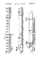
- FIG. 1 is a top plan view of a drydock in accordance with the preferred embodiments of the invention.
- FIG. 2 is a sectional view taken along lines 2--2 of FIG. 1;
- FIG. 3 is a sectional view taken along lines 3--3 of FIG. 2;
- FIG. 4 is a sectional view similar to FIG. 2 but illustrating a second embodiment of the invention.
- FIG. 5 is an exploded perspective view of a portion of the embodiment of FIG. 4;
- FIG. 6 is an enlarged view of a portion of FIG. 2;
- FIG. 7 is a sectional view similar to FIG. 2 illustrating a third embodiment of the invention.
- FIG. 8 is a sectional view taken along lines 8--8 of FIG. 7;
- FIG. 9 is a sectional view similar to FIG. 2 but illustrating a fourth embodiment of the invention.
- FIG. 1 of the drawings comprises a plan view of a drydock installation provided adjacent a body of water including a lifting platform support means consisting of a pair of parallel concrete piers 10 and 12 between which a slip 14 is provided of sufficient depth to receive ships or other vessels to be removed from the water for maintenance purposes.
- a vertically movable lifting platform 13 extends between the piers 10 and 12 and is supported for vertical movement by cable members 16 extending about pulley sheaves 18 (FIG. 3) mounted in the ends of main transverse support beam members 20 extending transversely across the width of the slip 14 as best illustrated in FIG. 1.
- Main transverse support beams 20 provide support for the remaining portions of the lifting platform including a plurality of longitudinal beams 22 connected to and supported by the main transverse support beams 20 in a manner to be discussed hereinafter.
- the longitudinal beams 22 provide support for secondary transverse support beams 24 connected to and supported on the upper surface of beams 22. It will be noted that alternate ones of the beams 24 extend substantially the entire width of the platform while the other beams merely extend between the longitudinal beams 22.
- Lifting platform 17 also includes upper timber decking components 26 supported on the upper surfaces of beams 20 and 24. Additionally, the platform 17 can include platform rail members 28 for supporting a movable railway type carriage if desired.
- Rail members 28 would be provided in alignment with inland transfer rails 30 for effecting movement of any such carriage from the platform inland away from the drydock such as for the purpose of conveying a ship or vessel to a work station.
- the arrangement of the main transverse support beams and the longitudinal beams 22 is of particular significance to the subject invention.
- Platform 17 is divided into a plurality of rigid unitary sections extending across the width of the platform and bounded by the main transverse lifting beams 20 with the construction in a first embodiment being as shown in FIG. 2.
- FIG. 2 illustrates two complete adjacent sections "A" and "B" of the platform with the remaining platform sections being connected in exactly the same manner along the entire length of the platform.
- the component parts of platforms "A" and "B"0 are designated by the same designators discussed above with the suffix "A” or "B” being added for the parts of the respective sections so as to provide a clear illustration of the extend of each section.
- the first platform section “A” consists of a single main transverse lifting beam 20A to the main vertical web of which the longitudinal beams 22A are welded as shown at 22 between an upper spacer plate 25 and a lower spacer plate 27.
- Secondary transverse support beams 24A are supported on the upper surface of the beams 22A with the timber decking 26 being supported on the upper surface of the beams as shown.
- the second complete section "B" which is adjacent the first section “A” consists of a main transverse support beam 20B and a pair of longitudinal beams 22B which are welded to the right side of the main web of main transverse beam 20B.
- the main transverse support beam 20B is provided on the left side of its main web with means for pivotally supporting the free ends of longitudinal beams 22A of the first platform section "A.”
- the pivotal support for the free end of beams 22A is best illustrated in FIGS. 3 and 6 (an identical support for a different beam 22G is also shown in FIG. 5) and includes a horizontal saddle plate 34 welded to the main web of beam 20B positioned above the lower flange of the main transverse beam between vertical stiffener plates 36 welded to beam 20B and spaced apart sufficiently to receive the end of beam 22A.
- An upwardly extending retaining lug 38 is welded to the upper surface of the saddle plate 34 to cooperate with a retaining lug 40 extending downwardly from the lower flange of beam 22A.
- Additional support for the saddle plate 34 is provided by a center support plate 42 welded between the lower surface of saddle plate 34 and a lower flange of the main transverse support beam 20B.
- the free end of the longitudinal beams 22A is pivotally supported with respect to the main transverse beam 20B so that the platform section A is capable of limited pivotal movement with respect to the platform section B.
- the pivotal connection between the free ends of the longitudinal beams 22 and the adjacent main transverse beam of the next adjacent section provides for sufficient movement of the platform to accommodate the unbalance of load on the platform as frequently occurs while the unitary rigid platform section provides adequate rigidity necessary for a stable support of the load on the platform.
- FIG. 4 illustrates a second embodiment of the invention
- FIG. 5 illustrates parts thereof, in which a multi-section platform is formed of two groups of platform sections consisting of alternate sections F and G respectively differing in the manner in which the longitudinal beams of the sections are connected to the main transverse support beams.
- the longitudinal beams 22F of sections F are welded at both ends to the support beams 20F in exactly the same manner that the beams 22A are welded to beams 20A in the obviously discussed embodiment of FIGS. 2 and 3.
- the secondary transverse beams 24F are welded to the upper surface of the longitudinal beams 22F in the same manner that the previously discussed beams 24A etc. are supported on their longitudinal beams.
- Section G has its longitudinal beams 22G pivotally connected to the main transverse support beams 20F adjacent each end of beams 22G in exactly the same manner that the free ends of beams 22A are connected to the beams 20B of the first embodiment and which is best illustrated in FIG. 5.
- FIGS. 4 and 5 also provides flexibility between adjacent sections while preventing the rotation of the main transverse support beams by torsional loads.
- FIG. 7 illustrates a variation in the embodiment of FIGS. 4 and 5 in that it constitutes a sectional view of a portion of a lifting platform in its upper limit position of movement (i.e. the highest position to which the winches can lift the platform) with the lowest possible water level LWL as shown with respect to the platform.
- the embodiment of FIGS. 7 and 8 is exactly identical to the embodiment of FIG. 4 with the exception that tank 50 is formed between upper plates 52, lower plates 54, the main webs of the main transverse support beams 20F and side plates 56 (only one of which is shown beneath a supplemental longitudinal beam 22').
- Tank 50 is subdivided by plates 58 and encloses blocks of expanded synthetic resinous material 60 such as that sold under the trademark "Styrofoam.”
- the buoyancy tank 50 cooperates with similar buoyancy tanks provided along the length of the platform in the sections F so that the buoyant effect of the tanks is equal to a substantial portion of the weight of the entire platform such as in the order of 75% to 90%, for example.
- buoyancy tanks 50 can obviously be varied in accordance with the weight of the particular platform with which they are associated. Additionally, it should be understood that buoyancy tanks of the type illustrated in FIGS. 7 and 8 can also be incorporated in the other embodiments of the invention by merely welding similar tanks to the lower surfaces of the longitudinal beams such as beams 22A of the embodiment of FIGS. 2 and 4. It is of critical importance that the buoyancy tanks 50 be located in the lower portion of the lifting platform so that they are always below the low water level LWL even when the platform is in its uppermost limit position as illustrated in FIG. 7 so that the buoyancy effect of the tanks is always provided to the fullest extent possible. Consequently, the weight of the platform is largely offset for all positions of the platform and the lower requirements of the lifting winches ae not nearly as great as they would be if it were not for the presence of the buoyancy tanks.
- FIG. 9 illustrates another embodiment quite similar to that of FIGS. 7 and 8 in that buoyancy tanks 50' are provided in the same location as buoyancy tanks 50.
- the buoyancy tanks 50' are different in that they are air tanks in that they do not incorporate resinous foam material in the manner of the tanks 50.
- Tanks 50' are connected to an air line 64 and have an inlet pipe 66 on their interior so that compressed air can be provided on the interior of the tanks to force the water in the tanks outwardly through valve means 70 to provide a desired amount of buoyancy.
- tank 50' is shown in its upper limit position of movement in conjunction with the lowest possible water level LWL and that the tank 50' is consequently always completely submerged below the water level so as to provide for its full buoyancy effect if desired.
- the buoyancy effect provided by tank 50' can be varied in accordance with the amount of air introduced into the tank.
Landscapes
- Engineering & Computer Science (AREA)
- Mechanical Engineering (AREA)
- Ocean & Marine Engineering (AREA)
- Handcart (AREA)
- Bridges Or Land Bridges (AREA)
- Harvesting Machines For Root Crops (AREA)
- Steroid Compounds (AREA)
- Revetment (AREA)
- Devices For Post-Treatments, Processing, Supply, Discharge, And Other Processes (AREA)
Priority Applications (9)
| Application Number | Priority Date | Filing Date | Title |
|---|---|---|---|
| US05/734,642 US4087979A (en) | 1976-10-21 | 1976-10-21 | Drydock lifting platform |
| GB41379/77A GB1586788A (en) | 1976-10-21 | 1977-10-05 | Drydock lifting platform |
| DE2746079A DE2746079C3 (de) | 1976-10-21 | 1977-10-13 | Trockendock-Hubplattform |
| NO773576A NO144664C (no) | 1976-10-21 | 1977-10-18 | Toerrdokkplattform. |
| JP12638777A JPS5353895A (en) | 1976-10-21 | 1977-10-19 | Lifting base of dry dock |
| ES463383A ES463383A1 (es) | 1976-10-21 | 1977-10-19 | Plataforma de elevacion de dique seco. |
| FR7731639A FR2368400A1 (fr) | 1976-10-21 | 1977-10-20 | Plate-forme de levage pour cale seche |
| ES472589A ES472589A1 (es) | 1976-10-21 | 1978-08-16 | Plataforma de elevacion de dique seco |
| HK665/83A HK66583A (en) | 1976-10-21 | 1983-12-15 | Drydock lifting platform |
Applications Claiming Priority (1)
| Application Number | Priority Date | Filing Date | Title |
|---|---|---|---|
| US05/734,642 US4087979A (en) | 1976-10-21 | 1976-10-21 | Drydock lifting platform |
Publications (1)
| Publication Number | Publication Date |
|---|---|
| US4087979A true US4087979A (en) | 1978-05-09 |
Family
ID=24952512
Family Applications (1)
| Application Number | Title | Priority Date | Filing Date |
|---|---|---|---|
| US05/734,642 Expired - Lifetime US4087979A (en) | 1976-10-21 | 1976-10-21 | Drydock lifting platform |
Country Status (8)
| Country | Link |
|---|---|
| US (1) | US4087979A (Direct) |
| JP (1) | JPS5353895A (Direct) |
| DE (1) | DE2746079C3 (Direct) |
| ES (2) | ES463383A1 (Direct) |
| FR (1) | FR2368400A1 (Direct) |
| GB (1) | GB1586788A (Direct) |
| HK (1) | HK66583A (Direct) |
| NO (1) | NO144664C (Direct) |
Cited By (7)
| Publication number | Priority date | Publication date | Assignee | Title |
|---|---|---|---|---|
| US4329082A (en) * | 1980-05-22 | 1982-05-11 | Gillis Michael E | Shiplift apparatus |
| WO1992022458A1 (en) * | 1991-06-18 | 1992-12-23 | Nei Syncrolift Incorporated | Method of determining and analyzing a ship's weight |
| WO1992022457A1 (en) * | 1991-06-18 | 1992-12-23 | Nei Syncrolift Incorporated | Method of distributing loads generated between a ship and a supporting dry dock |
| US5390616A (en) * | 1993-06-21 | 1995-02-21 | Roth; Henry | Dock mounted small boat lifting system |
| US5909715A (en) * | 1995-10-30 | 1999-06-08 | Menon; Prabhakaran Alek | Method of conversion of a vessel from single to double hull |
| US20080292402A1 (en) * | 2004-06-16 | 2008-11-27 | Attwater Iain J | Method of Operating a Shiplift |
| US20190106184A1 (en) * | 2017-10-06 | 2019-04-11 | Robert Taylor | Shiplift platform with movable connectors for connecting with piers |
Families Citing this family (3)
| Publication number | Priority date | Publication date | Assignee | Title |
|---|---|---|---|---|
| JPS57107697U (Direct) * | 1980-12-24 | 1982-07-02 | ||
| GB2276860A (en) * | 1993-02-11 | 1994-10-12 | Wise Handling Limited | Boat cradle |
| JPH0714296U (ja) * | 1993-08-23 | 1995-03-10 | 株式会社名空製作所 | エアツール用温空器 |
Citations (5)
| Publication number | Priority date | Publication date | Assignee | Title |
|---|---|---|---|---|
| US1380141A (en) * | 1918-07-06 | 1921-05-31 | Hamilton Thomas Hayden | Lifting-dock |
| US3073125A (en) * | 1958-12-03 | 1963-01-15 | Pearlson Engineering Company I | Drydock |
| US3265024A (en) * | 1965-06-14 | 1966-08-09 | Charles W Kramlich | Boat lift |
| US3626447A (en) * | 1969-10-22 | 1971-12-07 | Harry O Hindlin | Portable air inflated drydock |
| DE2132142A1 (de) * | 1971-06-29 | 1973-01-11 | Gutehoffnungshuette Sterkrade | Ein- oder mehrteilige schiffshebebuehne |
Family Cites Families (2)
| Publication number | Priority date | Publication date | Assignee | Title |
|---|---|---|---|---|
| GB1016785A (en) * | 1962-10-09 | 1966-01-12 | Hydraulik Leipzig Veb | Improvements in slip gear for ships |
| FR1528588A (fr) * | 1966-04-06 | 1968-06-14 | Installation pour la mise à sec et la mise à eau de navires |
-
1976
- 1976-10-21 US US05/734,642 patent/US4087979A/en not_active Expired - Lifetime
-
1977
- 1977-10-05 GB GB41379/77A patent/GB1586788A/en not_active Expired
- 1977-10-13 DE DE2746079A patent/DE2746079C3/de not_active Expired
- 1977-10-18 NO NO773576A patent/NO144664C/no unknown
- 1977-10-19 ES ES463383A patent/ES463383A1/es not_active Expired
- 1977-10-19 JP JP12638777A patent/JPS5353895A/ja active Granted
- 1977-10-20 FR FR7731639A patent/FR2368400A1/fr active Granted
-
1978
- 1978-08-16 ES ES472589A patent/ES472589A1/es not_active Expired
-
1983
- 1983-12-15 HK HK665/83A patent/HK66583A/xx not_active IP Right Cessation
Patent Citations (5)
| Publication number | Priority date | Publication date | Assignee | Title |
|---|---|---|---|---|
| US1380141A (en) * | 1918-07-06 | 1921-05-31 | Hamilton Thomas Hayden | Lifting-dock |
| US3073125A (en) * | 1958-12-03 | 1963-01-15 | Pearlson Engineering Company I | Drydock |
| US3265024A (en) * | 1965-06-14 | 1966-08-09 | Charles W Kramlich | Boat lift |
| US3626447A (en) * | 1969-10-22 | 1971-12-07 | Harry O Hindlin | Portable air inflated drydock |
| DE2132142A1 (de) * | 1971-06-29 | 1973-01-11 | Gutehoffnungshuette Sterkrade | Ein- oder mehrteilige schiffshebebuehne |
Cited By (28)
| Publication number | Priority date | Publication date | Assignee | Title |
|---|---|---|---|---|
| US4329082A (en) * | 1980-05-22 | 1982-05-11 | Gillis Michael E | Shiplift apparatus |
| WO1992022458A1 (en) * | 1991-06-18 | 1992-12-23 | Nei Syncrolift Incorporated | Method of determining and analyzing a ship's weight |
| WO1992022457A1 (en) * | 1991-06-18 | 1992-12-23 | Nei Syncrolift Incorporated | Method of distributing loads generated between a ship and a supporting dry dock |
| US5178488A (en) * | 1991-06-18 | 1993-01-12 | Nei Syncrolift Incorporated | Method of determining and analysing a ships weight |
| AU649199B2 (en) * | 1991-06-18 | 1994-05-12 | Syncrolift Inc. | Method of determining and analyzing a ship's weight |
| US5314263A (en) * | 1991-06-18 | 1994-05-24 | Nei Syncrolift Incorporated | Method of distributing loads generated between a ship and a supporting dry dock |
| AU651489B2 (en) * | 1991-06-18 | 1994-07-21 | Syncrolift Inc. | Method of distributing loads generated between a ship and a supporting dry dock |
| USRE36971E (en) * | 1991-06-18 | 2000-11-28 | Syncrolift, Inc. | Method of determining and analyzing a ship's weight |
| USRE37061E1 (en) * | 1991-06-18 | 2001-02-20 | Syncrolift, Inc. | Method of distributing loads generated between a ship and a supporting dry dock |
| US5390616A (en) * | 1993-06-21 | 1995-02-21 | Roth; Henry | Dock mounted small boat lifting system |
| US5909715A (en) * | 1995-10-30 | 1999-06-08 | Menon; Prabhakaran Alek | Method of conversion of a vessel from single to double hull |
| US20100292831A1 (en) * | 2004-06-16 | 2010-11-18 | Rolls-Royce Naval Marine, Inc. | Method of operating a shiplift |
| US8251609B2 (en) | 2004-06-16 | 2012-08-28 | Rolls-Royce Naval Marine, Inc. | Method of operating a shiplift |
| US7766577B2 (en) * | 2004-06-16 | 2010-08-03 | Rolls-Royce Naval Marine, Inc. | Method of operating a shiplift |
| US20080292402A1 (en) * | 2004-06-16 | 2008-11-27 | Attwater Iain J | Method of Operating a Shiplift |
| US20100292830A1 (en) * | 2004-06-16 | 2010-11-18 | Rolls-Royce Naval Marine, Inc. | Method of operating a shiplift |
| US20100298969A1 (en) * | 2004-06-16 | 2010-11-25 | Rolls-Royce Naval Marine, Inc. | Method of operating a shiplift |
| US20100298970A1 (en) * | 2004-06-16 | 2010-11-25 | Rolls-Royce Naval Marine, Inc. | Method of operating a shiplift |
| AU2005262532B2 (en) * | 2004-06-16 | 2011-11-24 | Tts Syncrolift As | Method of operating a shiplift |
| US8186908B2 (en) | 2004-06-16 | 2012-05-29 | Rolls-Royce Naval Marine, Inc. | Method of operating a shiplift |
| EP1765676A4 (en) * | 2004-06-16 | 2009-07-29 | Rolls Royce Naval Marine Inc | METHOD FOR OPERATING A DRY PLOWING PLATFORM |
| US8251608B2 (en) | 2004-06-16 | 2012-08-28 | Rolls-Royce Naval Marine, Inc. | Method of operating a shiplift |
| US8256303B2 (en) | 2004-06-16 | 2012-09-04 | Rolls-Royce Naval Marine, Inc. | Method of operating a shiplift |
| EP2511172A2 (en) | 2004-06-16 | 2012-10-17 | Rolls-Royce Naval Marine, Inc. | Method of operating a shiplift |
| EP2511171A2 (en) | 2004-06-16 | 2012-10-17 | Rolls-Royce Naval Marine, Inc. | Method of operating a shiplift |
| EP2511170A2 (en) | 2004-06-16 | 2012-10-17 | Rolls-Royce Naval Marine, Inc. | Method of operating a shiplift |
| US20190106184A1 (en) * | 2017-10-06 | 2019-04-11 | Robert Taylor | Shiplift platform with movable connectors for connecting with piers |
| US10577061B2 (en) * | 2017-10-06 | 2020-03-03 | Bardex Corporation | Shiplift platform with movable connectors for connecting with piers |
Also Published As
| Publication number | Publication date |
|---|---|
| NO773576L (no) | 1978-04-24 |
| ES472589A1 (es) | 1979-02-16 |
| ES463383A1 (es) | 1978-11-16 |
| GB1586788A (en) | 1981-03-25 |
| DE2746079C3 (de) | 1980-09-04 |
| HK66583A (en) | 1983-12-23 |
| DE2746079A1 (de) | 1978-05-03 |
| DE2746079B2 (de) | 1979-12-20 |
| JPS5353895A (en) | 1978-05-16 |
| NO144664B (no) | 1981-07-06 |
| FR2368400A1 (fr) | 1978-05-19 |
| JPS5550838B2 (Direct) | 1980-12-20 |
| FR2368400B1 (Direct) | 1983-12-02 |
| NO144664C (no) | 1981-10-14 |
Similar Documents
| Publication | Publication Date | Title |
|---|---|---|
| SU1308189A3 (ru) | Морское подъемно-транспортное грузовое плавсредство с регулируемой плавучестью | |
| US4940021A (en) | Floating dock | |
| US4709647A (en) | Floating dock | |
| US4979453A (en) | Floating dock system | |
| US4190013A (en) | Floating dry storage facility for small boats | |
| EP1753653B1 (en) | Floating platform | |
| US8091500B2 (en) | Over-the-water dock | |
| US4887654A (en) | Floating dock | |
| US3036539A (en) | Pontoon structure | |
| US2551375A (en) | Submergible drilling barge and method of operation | |
| US4087979A (en) | Drydock lifting platform | |
| US4070979A (en) | Floating dry storage facility for small boats | |
| SU648071A3 (ru) | Плавучий док | |
| GB1585922A (en) | Semi-submersible vessels providing a loading mooring and storage facility | |
| US5107784A (en) | Docking system for boats | |
| US4945595A (en) | Modular ramp assembly | |
| US3044269A (en) | Mobile sea platform | |
| US4286538A (en) | Multipurpose floating structure | |
| US3707934A (en) | Floating stable terminal | |
| US3999396A (en) | Marine platform assembly | |
| US6668747B2 (en) | Load transfer system | |
| WO1998026979A1 (en) | Transporter for heavy objects at sea | |
| US4085696A (en) | Utility chase for floating units | |
| SE500538C2 (sv) | Flytande plattformskonstruktion | |
| US3053216A (en) | Floatable housing |