US4082398A - Electrical connector with front and rear insertable and removable contacts - Google Patents
Electrical connector with front and rear insertable and removable contacts Download PDFInfo
- Publication number
- US4082398A US4082398A US05/728,820 US72882076A US4082398A US 4082398 A US4082398 A US 4082398A US 72882076 A US72882076 A US 72882076A US 4082398 A US4082398 A US 4082398A
- Authority
- US
- United States
- Prior art keywords
- contact
- passage
- insert
- fingers
- shoulders
- Prior art date
- Legal status (The legal status is an assumption and is not a legal conclusion. Google has not performed a legal analysis and makes no representation as to the accuracy of the status listed.)
- Expired - Lifetime
Links
Images


Classifications
-
- H—ELECTRICITY
- H01—ELECTRIC ELEMENTS
- H01R—ELECTRICALLY-CONDUCTIVE CONNECTIONS; STRUCTURAL ASSOCIATIONS OF A PLURALITY OF MUTUALLY-INSULATED ELECTRICAL CONNECTING ELEMENTS; COUPLING DEVICES; CURRENT COLLECTORS
- H01R13/00—Details of coupling devices of the kinds covered by groups H01R12/70 or H01R24/00 - H01R33/00
- H01R13/40—Securing contact members in or to a base or case; Insulating of contact members
- H01R13/42—Securing in a demountable manner
- H01R13/422—Securing in resilient one-piece base or case, e.g. by friction; One-piece base or case formed with resilient locking means
- H01R13/4223—Securing in resilient one-piece base or case, e.g. by friction; One-piece base or case formed with resilient locking means comprising integral flexible contact retaining fingers
- H01R13/4226—Securing in resilient one-piece base or case, e.g. by friction; One-piece base or case formed with resilient locking means comprising integral flexible contact retaining fingers comprising two or more integral flexible retaining fingers acting on a single contact
Definitions
- This invention relates to electrical connectors of the type having insertable and removable contacts.
- the invention is more particularly related to the molded contact retaining insert.
- Electrical connectors generally include a plug and receptacle, each of which has an insert of dielectric material provided with multiple openings within which electrical contacts are retained.
- the insert is introduced from the rearward end of the metallic shell where it is held in place by some means, such as a nut.
- Some connectors provide for rear insertion and release of electrical contacts while others provide for front insertion and release of electrical contacts.
- This invention is an electrical connector 1 that includes an insert 10 having a plurality of bores 15 therethrough, each of the bores having integral therewith a first plurality of radially deflectable contact retention fingers 11 facing an opposing second plurality of radially deflectable contact retention fingers 11.
- the insert allows an electrical contact 20 to be inserted and removed from either end of the electrical connector.
- the invention is an electrical connector insert 10 where an electrical contact may be inserted or removed from either the front or rear end of the connector 1.
- the insert 10 is characterized by a body of molded dielectric material having a plurality of passages 15 therethrough from a front face 18 to a rear face 19, each passage 15 including: a first plurality of truncated tubular contact retention cones or contact retention fingers 11 integral with said body 10 and located within the passage 15, each of the fingers 11 terminating in a free end 12 facing the same direction as one of the insert faces 18; and a second plurality of contact retention fingers 11 integral with said body 10 and located within the passage 15, each of the fingers 11 terminating in a free end 12 facing the direction of the other insert face 19, the free end of the first and second plurality of retention fingers defining a cavity A for releasably retaining the enlarged portion 25 of an electrical contact 20.
- Each of the fingers 11 being resiliently deflectable radially and substantially rigid in an axial direction when in their nondeflected position.
- FIG. 1 is a partial cross-sectional diagrammatic view of the contact retaining fingers of the electrical connector insert incorporating the principles of the invention.
- FIG. 2 is another partial cross-sectional diagrammatic view of the electrical connector insert incorporating the principles of this invention.
- FIG. 3 illustrates a cross-sectional view taken along line III--III in FIG. 2.
- FIG. 4 illustrates a cross-sectional view taken along line IV--IV in FIG. 2.
- FIG. 5 illustrates an alternate embodiment of the invention.
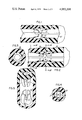
- FIGS. 6, 7, 8 and 9 illustrate how an electrical contact may be inserted from one end of the insert and removed from the opposite end.
- FIG. 10 illustrates an electrical connector assembly incorporating the principles of the invention.
- FIG. 11 illustrates an alternate embodiment of the invention.
- FIG. 12 is a cross-sectional view taken along line AA in FIG. 11.
- FIG. 13 is a cross-sectional view taken along line BB in FIG. 11.
- FIGS. 14 through 18 illustrate how one embodiment of the novel insert is molded.
- FIG. 19 is an end view of the molded insert taken along line CC in FIG. 18.
- FIGS. 20 through 23 illustrate how another embodiment of the novel insert is molded.
- FIG. 24 is an end view of a portion of the connector insert taken along line CC of FIG. 24.
- FIG. 1 illustrates a portion of an electrical connector insert that illustrates one embodiment of the invention.
- the insert is comprised of two identical pieces 10, each including a plurality of passages 15 having therein a plurality of radially deflectable contact retention fingers 11 integral with the insert.
- the fingers 11 are arranged in the shape of a truncated tubular contact retention cone which is resiliently expandable in a radial direction.
- the truncated contact retention cone 11 is not an integral part of the insert but is a wafer held between two inserts. Details of the function and shape of a contact retention cone may be found in U.S. Pat. No.
- a first truncated contact retention cone 11 is located coaxially within each passage 15 and tapers forwardly and radially inwardly from the wall of the passage 15 to a forward free end 12 which terminates a predetermined distance from the free end 12 of a second identical cone 11 facing in the opposite direction.
- the cones 11 are resiliently radially expandable.
- a plurality of resiliently radially deflectable contact retention fingers may be used instead of the specific truncated tubular retention cone shape shown. Details of such contact retention fingers and how they operate to retain a contact may be found in U.S. Pat. No. 3,727,172, hereby specifically incorporated by reference.
- FIG. 2 is another cross-sectional view of a dielectric insert 10 that includes two truncated tubular contact retention cones 11, each integral with one of the two pieces of the insert 10.
- the free ends 12 of the cones 11 define a space A, the function of which is to captivate the enlarged portion of an electrical contact (not shown).
- Annular shoulders 19 aid in centering a contact in the passage.
- FIG. 3 illustrates a partial cross-sectional view of the insert 10 taken along line III--III in FIG. 2.
- FIG. 4 illustrates a partial cross-sectional view of the insert 10 taken along line IV--IV in FIG. 2.
- FIG. 5 illustrates an alternate embodiment of the invention.
- each of the cones are formed from four resiliently deflectable fingers whereas in the preferred embodiment three resiliently deflectable fingers form the truncated tubular contact retention cone 11.
- an electrical contact is insertable into the insert 10 from either end as follows:
- the electrical contact 20 is inserted into the passage 15 from one of the faces 19.
- the enlarged portion 25 of the contact 20 deflects or expands the retention cone 11 radially outwardly as shown in FIG. 7. This allows the enlarged portion 25 of the contact to proceed into space A.
- the enlarged portion 25 of the contact 20 passes the free ends 12 of the contact retention cone 11, the cone contracts behind the contact shoulder 21 to prevent movement of the contact in the passage 15 toward the one face 19.
- the other free ends 12 engage the other shoulder 22 to prevent further movement of the contact 20 within the passage 15 toward the other face 18.
- FIG. 18 illustrates how the shoulders 19 locate the contact 20 in the passage 15 by engaging the enlarged portion 25 of the contact 20.
- FIG. 9 illustrates how the contact may be removed from the insert by a suitable tool (not shown), inserted into passage 15 to deflect the fingers 11 away from engagement with the shoulder 22 of the contact, allowing the contact to be removed from the insert from either end.
- FIG. 10 is one-half of an electrical connector assembly which incorporates the novel dielectric contact retention insert 10.
- the electrical connector includes: a one piece contact retaining insert 10; a plurality of contacts 20 retained by the insert 10; a rear moisture sealing grommet 30; a front moisture sealing grommet 40; a front retaining ring 110; a connector shell 90; a retaining nut 100; and a rear retaining ring 120.
- the other half of the connector assembly which is substantially identical to this half of the connector assembly except for the fact that the connector shell of the other half is mateable with this connector shell 90 and the contacts 20.
- the other half includes socket type contacts mateable with pin type contacts.
- This figure illustrates how the electrical contact 20 may be removed from the front or the rear of the connector shell 90.
- a suitable tool (not shown) is inserted through the passage in either the front grommet 40 or rear grommet 30 and into the insert 10 to deflect the retention fingers 11 and allow the contact 20 to be removed from the connector 1.
- a wire 3 is connected to each of the contacts 20.
- FIGS. 11, 12 and 13 illustrate another embodiment of the invention.
- an electrical contact is insertable from the rear or front of an electrical connector insert.
- the molded dielectric material which in this instance may be molded from a single piece includes a plurality of first shoulders 31, 32, 33 integral with the body in the passage 15, each of the shoulders 31, 32, 33 facing in the same direction as one of the insert faces 18.
- a second plurality of shoulders 41, 42, 43 integral with the body 10 in the passage 15 is arranged so that each of the second shoulders 41, 42, 43 face in the same direction as the other of the insert faces 19. All of the shoulders are resiliently radially deformable while being substantially rigid in the axial direction so that a contact may be forced into the space defined by the two pluralities of shoulders.
- each of the forward facing shoulders 31, 32, 33 and the rear of the facing shoulders 41, 42, 43 are comprised of arcuate segments approximately 30 radial degrees.
- the forwardly facing shoulders 31, 32, 33 are rotated approximately 45° from the axis of the rearwardly facing shoulders 41, 42, 43. This arrangement allows the insert 10 to be molded from one piece as opposed to being comprised of two identical pieces having a single annular ring of deformable dielectric material.
- FIGS. 14 through 18 illustrate how one embodiment of the novel dielectric contact retaining insert 10 is molded.
- the dielectric retention insert is made from a thermal, plastic resin, although other materials such as thermal setting materials may be used.
- materials are: polyester (valox); polyarylsulfone (B360 Astrel); polyethersulfone (torlon); polymides (nylon); acetates (deldrin); and polycarbonates (lexan).
- the polyester material sold under the trade name Valox is preferred along with polyarylsulfones and polyethersulfones.
- the foregoing materials have acceptable mechanical strength and electrical insulation characteristics which serve to increase the dielectric separation between adjacent contacts.
- FIG. 14 illustrates a portion of one half of the mold 70 having a plurality of core pins 50 mounted therein and a portion of the other half of the mold 80 having a plurality of core bushings mounted therein.
- the core pin 50 includes an axially extending projection 52 which mates with an axial passageway 62 in the bushing 60 in the other half 80 of the mold.
- FIG. 15 illustrates how the axial projection 52 of a core pin 50 in one half of a mold 70 mates with the passageway 62 in core bushing 60 located in the other half 80 of the mold.
- FIG. 16 illustrates a core pin 50 and a core bushing 60 in the fully mated position as well as the two halves 70 and 80 of the mold joined together to form a molding cavity B into which a thermal plastic material in liquid form is poured and allowed to harden.
- the mold cavity B includes a plurality of mated core pins and bushings to form a molded contact retaining insert capable of retaining a plurality of electrical contracts (not shown).
- the mold of course, has the appropriate means, such as passageways through the upper half of the mold 70 into cavity B, for filling and venting cavity B.
- FIG. 17 illustrates a completely molded contact retention insert 10 which includes integral therewith contact retaining fingers 11.
- the portion of the passage 15 in the cone portion of the insert 10 takes on a configuration of the core pin 50.
- FIG. 18 illustrates the two halves 70 and 80 of the mold separated and a portion of the insert 10 which was formed in the mold cavity. This figure illustrates the location of the radial shoulder 19 which functions to center the contact in the passageway 15 of the insert 10. This is accomplished by the radial shoulder 19 engaging the enlarged portion 25 (not shown) of the contact.
- FIG. 19 illustrates the contact retaining fingers 11 and radial shoulder 19 looking along line CC of the insert 10 shown in FIG. 18.
- This end view illustrates that in this embodiment there are three radial shoulders 19 for engaging the enlarged portion of a contact and centering the contact, and there are three contact retaining fingers 11 for engaging one of the shoulders of the enlarged portion of the contact to prevent movement of the contact once located in the insert.
- the insert for retaining contacts that may be inserted or removed from either end of a connector is comprised of two identical pieces. The identical pieces would be bonded together in face to face relationship so that the fingers 11 oppose each other as shown in FIG. 8.
- FIGS. 20 through 23 illustrate how another embodiment of the novel insert is molded.
- the insert to be molded will be comprised of a single unitary structure as opposed to the embodiment shown in FIGS. 14 through 18 which was comprised of two identical pieces bonded together in face to face relationship.
- FIG. 20 illustrates a portion of one half of the mold 70 having a plurality of core pins 50 mounted therein and a portion of the other half of the mold 80 having a plurality of core bushings 60 mounted therein.
- FIG. 21 illustrates the core pin 50 and the core bushing 60 in the fully mated position as well as the two halves 70 and 80 of the mold arranged to form a molding cavity B into which thermal plastic material in liquid form is received and allowed to harden.
- the mold cavity B includes a plurality of mated core pins and bushings, only one of each is shown, to form a molded contact retaining insert capable of retaining a plurality of electrical contacts (not shown).
- the mold of course, has the appropriate means, such as passageways, through the upper half of the mold 70 into cavity B, for filling and venting the cavity B.
- FIG. 22 illustrates a completely molded contact retention insert 10 which is a one piece unitary structure.
- the insert 10 includes integral therewith contact retaining fingers 11.
- the portion of the passage 15 in the core portion of the insert 10 takes on the configuration of the void formed between the core pin 50 and core bushing 60.
- FIG. 23 illustrates the one piece molded dielectric insert which was formed in mold cavity B.
- the insert includes two pairs of retaining fingers 11. One pair of contact retaining fingers 11a and 11b project toward one face 18 of the insert while the other pair 11c (11d not shown) face the direction of the other face 19 of the insert.
- FIG. 24 illustrates an end view of a portion of the insert 10 taken along lines CC in FIG. 24. This view illustrates the orientation of the four retaining fingers 11 and the four shoulders 19 that engaged the enlarged portion of a contact (not shown) to center the contact in the insert passage 15 (e.g. see FIG. 8).
- the cone or fingers 11 although radially deflectable, are generally rigid in an axial direction when in their contracted position so as to provide a positive stop against rearward movement of an electrical contact. Accordingly, it is intended that the illustrative and descriptive materials herein be used to illustrate the principles of the invention and not to limit the scope thereof.
Landscapes
- Connector Housings Or Holding Contact Members (AREA)
- Coupling Device And Connection With Printed Circuit (AREA)
Priority Applications (7)
| Application Number | Priority Date | Filing Date | Title |
|---|---|---|---|
| US05/728,820 US4082398A (en) | 1976-10-01 | 1976-10-01 | Electrical connector with front and rear insertable and removable contacts |
| CA276,549A CA1073069A (en) | 1976-10-01 | 1977-04-20 | Electrical connector with front and rear insertable and removable contacts |
| GB33953/77A GB1543480A (en) | 1976-10-01 | 1977-08-12 | Electrical connector insert with front and rear insertable and removable contacts |
| FR7725381A FR2366716A1 (fr) | 1976-10-01 | 1977-08-19 | Garniture de connecteur electrique |
| JP10832477A JPS5343887A (en) | 1976-10-01 | 1977-09-08 | Insert of connector |
| IT28014/77A IT1084779B (it) | 1976-10-01 | 1977-09-28 | Connettore elettrico |
| DE2744155A DE2744155C3 (de) | 1976-10-01 | 1977-09-30 | Kontakteinsatz für einen elektrischen Steckverbinder |
Applications Claiming Priority (1)
| Application Number | Priority Date | Filing Date | Title |
|---|---|---|---|
| US05/728,820 US4082398A (en) | 1976-10-01 | 1976-10-01 | Electrical connector with front and rear insertable and removable contacts |
Publications (1)
| Publication Number | Publication Date |
|---|---|
| US4082398A true US4082398A (en) | 1978-04-04 |
Family
ID=24928399
Family Applications (1)
| Application Number | Title | Priority Date | Filing Date |
|---|---|---|---|
| US05/728,820 Expired - Lifetime US4082398A (en) | 1976-10-01 | 1976-10-01 | Electrical connector with front and rear insertable and removable contacts |
Country Status (7)
| Country | Link |
|---|---|
| US (1) | US4082398A (enExample) |
| JP (1) | JPS5343887A (enExample) |
| CA (1) | CA1073069A (enExample) |
| DE (1) | DE2744155C3 (enExample) |
| FR (1) | FR2366716A1 (enExample) |
| GB (1) | GB1543480A (enExample) |
| IT (1) | IT1084779B (enExample) |
Cited By (37)
| Publication number | Priority date | Publication date | Assignee | Title |
|---|---|---|---|---|
| US4194355A (en) * | 1977-02-26 | 1980-03-25 | Citizen Watch Co., Ltd. | Connection structure for watch case and band |
| DE2939474A1 (de) * | 1978-10-02 | 1980-04-10 | Bendix Corp | Elektrischer steckverbinder |
| DE3005337A1 (de) * | 1979-02-28 | 1980-09-18 | Bendix Corp | Elektrischer steckverbinder |
| US4264116A (en) * | 1979-08-31 | 1981-04-28 | The Bendix Corporation | Filter connector with adaptor for quick disconnection |
| US4274702A (en) * | 1979-11-14 | 1981-06-23 | The Bendix Corporation | Antirotation means for wire wrap electrical connector assemblies |
| US4293180A (en) * | 1978-05-31 | 1981-10-06 | Bunker Ramo Corporation | Resilient biasing means |
| US4312125A (en) * | 1979-12-03 | 1982-01-26 | The Bendix Corporation | Method and apparatus for automatically inserting an electrical contact into an electrical connector |
| US4356626A (en) * | 1979-12-03 | 1982-11-02 | The Bendix Corporation | Apparatus for automatically inserting an electrical contact into an electrical connector |
| US4362350A (en) * | 1980-06-09 | 1982-12-07 | International Telephone And Telegraph Corporation | Contact retention assembly |
| US4386816A (en) * | 1981-06-30 | 1983-06-07 | The Bendix Corporation | Electrical connector insert assembly |
| US4387943A (en) * | 1981-06-30 | 1983-06-14 | The Bendix Corporation | Electrical connector having front or rear releasable and removable contacts |
| US4387945A (en) * | 1981-06-30 | 1983-06-14 | The Bendix Corporation | Electrical connector insert |
| US4387944A (en) * | 1981-06-30 | 1983-06-14 | The Bendix Corporation | Electrical connector insert |
| US4395083A (en) * | 1981-06-30 | 1983-07-26 | The Bendix Corporation | Electrical connector having removable contacts |
| US4406507A (en) * | 1981-06-30 | 1983-09-27 | The Bendix Corporation | Electrical connector insert |
| US4421378A (en) * | 1979-11-07 | 1983-12-20 | The Bendix Corporation | Electrical contact retention insert and means for molding same |
| US4433482A (en) | 1979-11-15 | 1984-02-28 | The Bendix Corporation | Method of making an electrical contact |
| US4573754A (en) * | 1984-03-14 | 1986-03-04 | U.S. Plastics Corp. | Lamp assembly |
| US4636020A (en) * | 1983-05-31 | 1987-01-13 | Allied Corporation | Insert for an electrical connector |
| US4684187A (en) * | 1984-06-29 | 1987-08-04 | Amp Incorporated | Retention article for electrical contacts |
| US4772229A (en) * | 1984-07-30 | 1988-09-20 | Amp Incorporated | Plug connector having separate terminal retaining member |
| US4776816A (en) * | 1981-12-29 | 1988-10-11 | Souriau & Cie | Electrical connector |
| US4850898A (en) * | 1985-07-18 | 1989-07-25 | Amphenol Corporation | Electrical connector having a contact retention |
| US6713711B2 (en) | 2001-11-09 | 2004-03-30 | Thermal Dynamics Corporation | Plasma arc torch quick disconnect |
| US6773304B2 (en) | 2001-11-09 | 2004-08-10 | Thermal Dynamics Corporation | Tamper resistant pin connection |
| US6848942B1 (en) * | 2000-01-12 | 2005-02-01 | Molex Incorporated | Connectors having supportive barrier components |
| US20100029143A1 (en) * | 2008-08-01 | 2010-02-04 | Tyco Electronics Corporation | Contact retention assembly |
| US20100210151A1 (en) * | 2009-02-13 | 2010-08-19 | Amphenol Corporation | Electrical contacts |
| US20110028021A1 (en) * | 2009-07-28 | 2011-02-03 | Jared Evan Rossman | Electrical connector having a dielectric insert for retaining an electrical contact |
| US20110076883A1 (en) * | 2009-09-30 | 2011-03-31 | Eric Jol | Portable electronic devices with sealed connectors |
| US20110230074A1 (en) * | 2010-03-19 | 2011-09-22 | Mathias Schmidt | Sealed connectors for portable electronic devices |
| US9559452B1 (en) * | 2015-08-07 | 2017-01-31 | Amphenol Corporation | Housing for electrical contact |
| US9722041B2 (en) | 2012-09-19 | 2017-08-01 | Vishay-Siliconix | Breakdown voltage blocking device |
| US10396485B1 (en) * | 2018-04-05 | 2019-08-27 | Delphi Technologies, Llc | Electrical connector assembly |
| US10720728B2 (en) | 2018-11-13 | 2020-07-21 | Ge Aviation Systems Llc | Electrical connector sealing system |
| US20210408699A1 (en) * | 2020-06-26 | 2021-12-30 | Ge Aviation Systems Llc | Crimp pin electrical connector |
| US11336049B1 (en) * | 2020-10-30 | 2022-05-17 | Amphenol Corporation | Sealed electrical connector and method of sealing |
Families Citing this family (5)
| Publication number | Priority date | Publication date | Assignee | Title |
|---|---|---|---|---|
| US4394058A (en) * | 1981-06-30 | 1983-07-19 | The Bendix Corporation | Electrical connector insert assembly |
| FR2658667B1 (fr) * | 1990-02-19 | 1994-06-24 | Itt Composants Instr | Element de connecteur electrique. |
| JPH056692U (ja) * | 1991-07-01 | 1993-01-29 | 矢崎総業株式会社 | コネクタ |
| DE4240261C2 (de) * | 1992-12-01 | 1995-09-28 | Itt Cannon Gmbh | Steckverbinder |
| DE102013113878B4 (de) * | 2013-12-11 | 2020-03-26 | HARTING Electronics GmbH | Steckverbinder mit Einzeladerabdichtung |
Citations (5)
| Publication number | Priority date | Publication date | Assignee | Title |
|---|---|---|---|---|
| US3165369A (en) * | 1962-08-13 | 1965-01-12 | Itt | Retention system for electrical contacts |
| US3227172A (en) * | 1962-05-31 | 1966-01-04 | Davy & United Eng Co Ltd | Pressure regulating valve with balanced spring adjusting means |
| US3383642A (en) * | 1965-09-02 | 1968-05-14 | Pyle National Co | Wire splice |
| DE2020077A1 (de) * | 1970-04-24 | 1971-11-11 | Amphenol Tuchel Elect | Flachkontakt,beispielsweise Kontaktmesser,fuer elektrische Leitungsverbindungen |
| US3648213A (en) * | 1966-08-15 | 1972-03-07 | Amp Inc | Electrical housing member |
Family Cites Families (1)
| Publication number | Priority date | Publication date | Assignee | Title |
|---|---|---|---|---|
| GB1443193A (en) * | 1972-09-27 | 1976-07-21 | Bunker Ramo | Electrical two-part connectors |
-
1976
- 1976-10-01 US US05/728,820 patent/US4082398A/en not_active Expired - Lifetime
-
1977
- 1977-04-20 CA CA276,549A patent/CA1073069A/en not_active Expired
- 1977-08-12 GB GB33953/77A patent/GB1543480A/en not_active Expired
- 1977-08-19 FR FR7725381A patent/FR2366716A1/fr active Granted
- 1977-09-08 JP JP10832477A patent/JPS5343887A/ja active Pending
- 1977-09-28 IT IT28014/77A patent/IT1084779B/it active
- 1977-09-30 DE DE2744155A patent/DE2744155C3/de not_active Expired
Patent Citations (5)
| Publication number | Priority date | Publication date | Assignee | Title |
|---|---|---|---|---|
| US3227172A (en) * | 1962-05-31 | 1966-01-04 | Davy & United Eng Co Ltd | Pressure regulating valve with balanced spring adjusting means |
| US3165369A (en) * | 1962-08-13 | 1965-01-12 | Itt | Retention system for electrical contacts |
| US3383642A (en) * | 1965-09-02 | 1968-05-14 | Pyle National Co | Wire splice |
| US3648213A (en) * | 1966-08-15 | 1972-03-07 | Amp Inc | Electrical housing member |
| DE2020077A1 (de) * | 1970-04-24 | 1971-11-11 | Amphenol Tuchel Elect | Flachkontakt,beispielsweise Kontaktmesser,fuer elektrische Leitungsverbindungen |
Cited By (45)
| Publication number | Priority date | Publication date | Assignee | Title |
|---|---|---|---|---|
| US4194355A (en) * | 1977-02-26 | 1980-03-25 | Citizen Watch Co., Ltd. | Connection structure for watch case and band |
| US4293180A (en) * | 1978-05-31 | 1981-10-06 | Bunker Ramo Corporation | Resilient biasing means |
| DE2939474A1 (de) * | 1978-10-02 | 1980-04-10 | Bendix Corp | Elektrischer steckverbinder |
| DE3005337A1 (de) * | 1979-02-28 | 1980-09-18 | Bendix Corp | Elektrischer steckverbinder |
| US4264116A (en) * | 1979-08-31 | 1981-04-28 | The Bendix Corporation | Filter connector with adaptor for quick disconnection |
| US4421378A (en) * | 1979-11-07 | 1983-12-20 | The Bendix Corporation | Electrical contact retention insert and means for molding same |
| US4274702A (en) * | 1979-11-14 | 1981-06-23 | The Bendix Corporation | Antirotation means for wire wrap electrical connector assemblies |
| US4433482A (en) | 1979-11-15 | 1984-02-28 | The Bendix Corporation | Method of making an electrical contact |
| US4312125A (en) * | 1979-12-03 | 1982-01-26 | The Bendix Corporation | Method and apparatus for automatically inserting an electrical contact into an electrical connector |
| US4356626A (en) * | 1979-12-03 | 1982-11-02 | The Bendix Corporation | Apparatus for automatically inserting an electrical contact into an electrical connector |
| US4362350A (en) * | 1980-06-09 | 1982-12-07 | International Telephone And Telegraph Corporation | Contact retention assembly |
| US4406507A (en) * | 1981-06-30 | 1983-09-27 | The Bendix Corporation | Electrical connector insert |
| US4387944A (en) * | 1981-06-30 | 1983-06-14 | The Bendix Corporation | Electrical connector insert |
| US4395083A (en) * | 1981-06-30 | 1983-07-26 | The Bendix Corporation | Electrical connector having removable contacts |
| US4387945A (en) * | 1981-06-30 | 1983-06-14 | The Bendix Corporation | Electrical connector insert |
| US4387943A (en) * | 1981-06-30 | 1983-06-14 | The Bendix Corporation | Electrical connector having front or rear releasable and removable contacts |
| US4386816A (en) * | 1981-06-30 | 1983-06-07 | The Bendix Corporation | Electrical connector insert assembly |
| US4776816A (en) * | 1981-12-29 | 1988-10-11 | Souriau & Cie | Electrical connector |
| US4636020A (en) * | 1983-05-31 | 1987-01-13 | Allied Corporation | Insert for an electrical connector |
| US4573754A (en) * | 1984-03-14 | 1986-03-04 | U.S. Plastics Corp. | Lamp assembly |
| US4684187A (en) * | 1984-06-29 | 1987-08-04 | Amp Incorporated | Retention article for electrical contacts |
| US4772229A (en) * | 1984-07-30 | 1988-09-20 | Amp Incorporated | Plug connector having separate terminal retaining member |
| US4850898A (en) * | 1985-07-18 | 1989-07-25 | Amphenol Corporation | Electrical connector having a contact retention |
| US6848942B1 (en) * | 2000-01-12 | 2005-02-01 | Molex Incorporated | Connectors having supportive barrier components |
| US6773304B2 (en) | 2001-11-09 | 2004-08-10 | Thermal Dynamics Corporation | Tamper resistant pin connection |
| US6713711B2 (en) | 2001-11-09 | 2004-03-30 | Thermal Dynamics Corporation | Plasma arc torch quick disconnect |
| US20100029143A1 (en) * | 2008-08-01 | 2010-02-04 | Tyco Electronics Corporation | Contact retention assembly |
| US7736199B2 (en) * | 2008-08-01 | 2010-06-15 | Tyco Electronics Corp. | Contact retention assembly |
| US20100210151A1 (en) * | 2009-02-13 | 2010-08-19 | Amphenol Corporation | Electrical contacts |
| US7850495B2 (en) | 2009-02-13 | 2010-12-14 | Amphenol Corporation | Electrical contacts |
| US20110028021A1 (en) * | 2009-07-28 | 2011-02-03 | Jared Evan Rossman | Electrical connector having a dielectric insert for retaining an electrical contact |
| US7887368B1 (en) * | 2009-07-28 | 2011-02-15 | Tyco Electronics Corporation | Electrical connector having a dielectric insert for retaining an electrical contact |
| US8506327B2 (en) | 2009-09-30 | 2013-08-13 | Eric Jol | Portable electronic devices with sealed connectors |
| US20110076883A1 (en) * | 2009-09-30 | 2011-03-31 | Eric Jol | Portable electronic devices with sealed connectors |
| US20110230074A1 (en) * | 2010-03-19 | 2011-09-22 | Mathias Schmidt | Sealed connectors for portable electronic devices |
| KR101283152B1 (ko) | 2010-03-19 | 2013-07-05 | 애플 인크. | 휴대용 전자 장치용의 밀봉된 커넥터 |
| US8246383B2 (en) * | 2010-03-19 | 2012-08-21 | Apple Inc. | Sealed connectors for portable electronic devices |
| US8925195B2 (en) | 2010-03-19 | 2015-01-06 | Apple Inc. | Methods for forming sealed connectors for portable electronic devices |
| US9722041B2 (en) | 2012-09-19 | 2017-08-01 | Vishay-Siliconix | Breakdown voltage blocking device |
| US9559452B1 (en) * | 2015-08-07 | 2017-01-31 | Amphenol Corporation | Housing for electrical contact |
| US10396485B1 (en) * | 2018-04-05 | 2019-08-27 | Delphi Technologies, Llc | Electrical connector assembly |
| US10720728B2 (en) | 2018-11-13 | 2020-07-21 | Ge Aviation Systems Llc | Electrical connector sealing system |
| US20210408699A1 (en) * | 2020-06-26 | 2021-12-30 | Ge Aviation Systems Llc | Crimp pin electrical connector |
| US11791571B2 (en) * | 2020-06-26 | 2023-10-17 | Ge Aviation Systems Llc | Crimp pin electrical connector |
| US11336049B1 (en) * | 2020-10-30 | 2022-05-17 | Amphenol Corporation | Sealed electrical connector and method of sealing |
Also Published As
| Publication number | Publication date |
|---|---|
| GB1543480A (en) | 1979-04-04 |
| FR2366716B1 (enExample) | 1981-12-04 |
| JPS5343887A (en) | 1978-04-20 |
| DE2744155A1 (de) | 1978-04-06 |
| CA1073069A (en) | 1980-03-04 |
| DE2744155C3 (de) | 1981-03-12 |
| DE2744155B2 (de) | 1980-08-07 |
| IT1084779B (it) | 1985-05-28 |
| FR2366716A1 (fr) | 1978-04-28 |
Similar Documents
| Publication | Publication Date | Title |
|---|---|---|
| US4082398A (en) | Electrical connector with front and rear insertable and removable contacts | |
| US4358179A (en) | Molded electrical connector insert | |
| US4187272A (en) | Method of making molded electrical connector insert | |
| US4832615A (en) | Sealed connector having unitary molded housing | |
| EP0079120B1 (en) | Electrical connector | |
| US3953099A (en) | One-piece environmental removable contact connector | |
| KR970003359B1 (ko) | 내부 탕구계를 가진 이중 주조 밀봉 코넥터 | |
| US6450829B1 (en) | Snap-on plug coaxial connector | |
| EP0782774B1 (en) | Overmold strain relief and snag prevention feature | |
| US5823811A (en) | Sealed electrical connector | |
| US4443052A (en) | Means to indicate fully-mated condition of electrical connector | |
| US3001167A (en) | Multi-conductor electrical connector | |
| US4361374A (en) | Electrical connector bayonet coupling pin | |
| US3733577A (en) | Electrical two-part connectors | |
| GB2277413A (en) | High density electrical connector | |
| US3478305A (en) | Electrical connector | |
| JPH03156866A (ja) | 2次ロック型電気コネクタ | |
| JPH06275333A (ja) | コネクタ用端子 | |
| US4090772A (en) | Low insertion force electrical connector | |
| US4636020A (en) | Insert for an electrical connector | |
| JP2995934B2 (ja) | 接続コネクタ | |
| EP0154412B1 (en) | Electrical connectors | |
| US3845459A (en) | Dielectric sleeve for electrically and mechanically protecting exposed female contacts of an electrical connector | |
| US4387943A (en) | Electrical connector having front or rear releasable and removable contacts | |
| US4378103A (en) | Electrical contact retention insert and means for molding same |
Legal Events
| Date | Code | Title | Description |
|---|---|---|---|
| STCF | Information on status: patent grant |
Free format text: PATENTED FILE - (OLD CASE ADDED FOR FILE TRACKING PURPOSES) |
|
| AS | Assignment |
Owner name: ALLIED CORPORATION, A CORP. OF NY Free format text: MERGER;ASSIGNOR:BENDIX CORPORATION, THE,;REEL/FRAME:004765/0709 Effective date: 19850401 Owner name: CANADIAN IMPERIAL BANK OF COMMERCE, NEW YORK AGENC Free format text: SECURITY INTEREST;ASSIGNOR:AMPHENOL CORPORATION;REEL/FRAME:004879/0030 Effective date: 19870515 |
|
| AS | Assignment |
Owner name: AMPHENOL CORPORATION, LISLE, ILLINOIS A CORP. OF D Free format text: ASSIGNMENT OF ASSIGNORS INTEREST.;ASSIGNOR:ALLIED CORPORATION, A CORP. OF NY;REEL/FRAME:004844/0850 Effective date: 19870602 Owner name: AMPHENOL CORPORATION, A CORP. OF DE, ILLINOIS Free format text: ASSIGNMENT OF ASSIGNORS INTEREST;ASSIGNOR:ALLIED CORPORATION, A CORP. OF NY;REEL/FRAME:004844/0850 Effective date: 19870602 |
|
| AS | Assignment |
Owner name: BANKERS TRUST COMPANY, AS AGENT Free format text: SECURITY INTEREST;ASSIGNOR:AMPHENOL CORPORATION, A CORPORATION OF DE;REEL/FRAME:006035/0283 Effective date: 19911118 |
|
| AS | Assignment |
Owner name: AMPHENOL CORPORATION A CORP. OF DELAWARE Free format text: RELEASED BY SECURED PARTY;ASSIGNOR:CANADIAN IMPERIAL BANK OF COMMERCE;REEL/FRAME:006147/0887 Effective date: 19911114 |
|
| AS | Assignment |
Owner name: AMPHENOL CORPORATION, CONNECTICUT Free format text: RELEASE BY SECURED PARTY;ASSIGNOR:BANKERS TRUST COMPANY;REEL/FRAME:007317/0148 Effective date: 19950104 |