US4078202A - Apparatus for detecting wire joint - Google Patents
Apparatus for detecting wire joint Download PDFInfo
- Publication number
- US4078202A US4078202A US05/698,409 US69840976A US4078202A US 4078202 A US4078202 A US 4078202A US 69840976 A US69840976 A US 69840976A US 4078202 A US4078202 A US 4078202A
- Authority
- US
- United States
- Prior art keywords
- wire
- detecting element
- detecting
- traveling
- metallic
- Prior art date
- Legal status (The legal status is an assumption and is not a legal conclusion. Google has not performed a legal analysis and makes no representation as to the accuracy of the status listed.)
- Expired - Lifetime
Links
- 229910001220 stainless steel Inorganic materials 0.000 claims description 3
- 239000010935 stainless steel Substances 0.000 claims description 3
- 238000012545 processing Methods 0.000 abstract description 2
- 238000003466 welding Methods 0.000 description 18
- 238000010438 heat treatment Methods 0.000 description 11
- 230000002159 abnormal effect Effects 0.000 description 8
- 238000000034 method Methods 0.000 description 7
- XEEYBQQBJWHFJM-UHFFFAOYSA-N Iron Chemical compound [Fe] XEEYBQQBJWHFJM-UHFFFAOYSA-N 0.000 description 6
- 230000005856 abnormality Effects 0.000 description 6
- 238000001514 detection method Methods 0.000 description 5
- 229910052742 iron Inorganic materials 0.000 description 3
- 238000012423 maintenance Methods 0.000 description 3
- 238000010586 diagram Methods 0.000 description 2
- WABPQHHGFIMREM-UHFFFAOYSA-N lead(0) Chemical compound [Pb] WABPQHHGFIMREM-UHFFFAOYSA-N 0.000 description 2
- 230000007246 mechanism Effects 0.000 description 2
- 230000010355 oscillation Effects 0.000 description 2
- 230000008569 process Effects 0.000 description 2
- 238000004804 winding Methods 0.000 description 2
- 239000003990 capacitor Substances 0.000 description 1
- 230000008859 change Effects 0.000 description 1
- 230000007547 defect Effects 0.000 description 1
- 230000002950 deficient Effects 0.000 description 1
- 238000011161 development Methods 0.000 description 1
- 238000012986 modification Methods 0.000 description 1
- 230000004048 modification Effects 0.000 description 1
- 230000009467 reduction Effects 0.000 description 1
- 239000003381 stabilizer Substances 0.000 description 1
Images

Classifications
-
- G—PHYSICS
- G01—MEASURING; TESTING
- G01N—INVESTIGATING OR ANALYSING MATERIALS BY DETERMINING THEIR CHEMICAL OR PHYSICAL PROPERTIES
- G01N27/00—Investigating or analysing materials by the use of electric, electrochemical, or magnetic means
- G01N27/02—Investigating or analysing materials by the use of electric, electrochemical, or magnetic means by investigating impedance
- G01N27/22—Investigating or analysing materials by the use of electric, electrochemical, or magnetic means by investigating impedance by investigating capacitance
- G01N27/24—Investigating the presence of flaws
Definitions
- the wire is subjected to a heat treatment before drawing.
- the heat treatment is continuously carried out on the wire in a strand form, from the viewpoint of job efficiency.
- the wires to be supplied to a heat treatment furnace are continuous ones which are connected by butt welding or the like. More specifically, as shown in FIG. 1, the terminal end part of a wire (a) and the initial end part of a wire (b) are connected by such a butt welding operation. A welding burr exists at the connected part.
- a wire having a diameter of 1.0 - 15 mm will give rise to a burr whose width, or axial extent, taken in the traveling direction of the wire, is about 3 - 10 mm and whose diameter is about 1.5 - 40 mm.
- Such welding burrs are cut off and discarded at the point of take-up of the wire after completion of the heat treatment, so that they are not mixed in a coil of the wire so taken up. Accordingly, an operator engaged in the take-up of the wire after it has been subjected to such heat treatment has been responsible for conducting the job of reliably cutting off and discarding the welding burr parts during the take-up of the wire, while continuously observing them.
- the welding burr part In order to facilitate the detection of the welding burr part, i.e., the connected position of the wire, the welding burr part has hitherto beeen made conspicuous or attractive by winding a fine iron wire or the like round the welding burr part.
- the use of the fine iron wire or the like is based on the fact that, since the stranded wire passes through the heat treatment furnace at a high temperature, conventional display means, such as coloration, cannot be utilized for the detection of the connected position.
- the fine iron wire, or the like is suitable as one which keeps its original form even when heated to the extent of the heat treatment temperature. All the pertinent jobs, however, rely on manpower. In particular, the passage of the wire subjected to the heat treatment need be continually observed in order to detect the connected positions. This has required much labor. Moreover, the detection precision has tended to become lower, especially as the number of wires to be processed and the processing speed thereof is increased.
- U.S. Pat. No. 3,812,424 has proposed an expedient in which the cross sectional area of a wire is gauged by measuring an electrostatic capacity.
- a sensing electrode is formed in a manner to surround one wire.
- a number of electrodes are required according to the number of the wires. It is accordingly difficult to detect the welded joints of the plurality of wires at a stroke.
- Further means to detect defective parts by measuring electrostatic capacities are taught in U.S. Pat. Nos. 2,565,500; 3,052,826; 3,519,922; 3,684,089; 3,764,899; 3,827,296 and 3,879,660 and DT-OS's No.
- This invention has a primary objective of eliminating the disadvantages of the prior art devices and providing an improved detecting apparatus which is most suitable for detecting a welded joint, an entangled part and/or a disconnected part of a wire during the continuous heat treatment of the wire.
- Another object of this invention is to provide a detecting apparatus of simple structure and high reliability which detects such welded joints, entangled parts and/or disconnected parts of a plurality of metallic wires automatically and at the same time.
- a further object of this invention is to provide a detecting apparatus which makes unnecessary the labor having heretofore been required for observing a welded joint, an entangled part and/or a disconnected part of a wire and which achieves a reduction in the running cost as well as the maintenance cost of an equipment line in a wire continuous heat treatment line.
- a yet further object of this invention is to provide a detecting apparatus which is low in maintenance expenses and long in life.
- a still further object of this invention is to provide a detecting apparatus which, even in the case of abnormalities of a large number of wires traveling in parallel relation, can discern which, if any, of such wires is abnormal.
- a first aspect of this invention for accomplishing the above-mentioned or other objects resides in apparatus wherein a variation in the electrostatic capacity between a metallic wire traveling continuously and a detecting element is sensed and an abnormality, such as a welded joint, a disconnected part or an entangled part of the wire, being a member to be detected, is detected, characterized by a detecting element which is so supported as to be displaceable when pressed by the metallic wire, an auxiliary roller which is disposed at a position opposite to the detecting element with the member to be detected intervening therebetween, a pair of guide rollers which are disposed before and behind the detecting element in the traveling direction of the wire, and a pair of press rollers which are disposed on the same side as that of the detecting element and between the detecting element and the guide rollers in order to normally hold the member to be detected in contact with the auxiliary roller.
- a second aspect of this invention resides in the apparatus of the first aspect characterized in that welded joints, disconnected parts and/or entangled parts of a plurality of metallic wires traveling in parallel paths continuously can be detected by a single detecting element.
- a third aspect of this invention resides in the apparatus of the first aspect characterized in that the welded joint and/or entangled part of the metallic wire traveling continuously are/is held in direct contact with the detecting element.
- a fourth aspect of this invention resides in the apparatus of the first aspect characterized in that the detecting element is a stainless steel pipe which is suspended by a chain.
- a fifth aspect of this invention resides in the apparatus of the first aspect characterized in that, in detecting welded joints, disconnected parts and/or entangled parts of a plurality of metallic wires, the plurality of metallic wires are grouped into a plurality of blocks, one detecting element being provided for each of the blocks, whereby the block of the metallic wires having a welded joint, disconnected part and/or entangled part can be detected.
- a sixth aspect of this invention resides in the apparatus of the first asepct characterized in that a transformer is interposed between a control circuit for detecting the variation in the electrostatic capacity between the detecting element and the member to be detected and a power input circuit for said control circuit, whereby the control circuit is not damaged even when the detecting element and the welded joint and/or entangled part of the member to be detected come into direct contact.
- FIG. 1 is a side view showing a welding burr at the connected part of a metallic wire, already described;
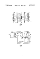
- FIG. 2 is a schematic side view of the apparatus of this invention.
- FIG. 3 is a perspective view showing one aspect of performance of the apparatus of this invention.
- FIG. 4 is a plan view showing another aspect of performance of the apparatus of this invention.
- FIG. 5 is a circuit diagram showing a control circuit and a power input circuit of the apparatus of this invention.
- FIG. 2 is a model diagram which shows an embodiment of the apparatus of this invention.
- a wire 1 which travels in the direction of an arrow, indicated at the right of the figure, passes between a detecting element 2, suspended by a chain 6, and an auxiliary roller 3, which is disposed at a position opposite to the detecting element 2.
- a welding burr at the welded joint of the wire 1 passes over the auxiliary roller 3, the wire is pushed up, so that the welded joint can be reliably detected.
- a grooved guide roller 4 is disposed on both sides of the detecting element 2 and auxiliary roll 3, and between the guide rollers 4 and the detecting element 2 there are disposed press rollers 5, which cause the wire 1 to normally lie in contact with the auxiliary roller 3.
- press rollers 5 which cause the wire 1 to normally lie in contact with the auxiliary roller 3.
- the wires 1 which are being taken up in the direction indicated by an arrow at the right of the figure by a winding machine, not shown, pass between an elongate auxiliary roller 3 traversing the wires and the detecting element 2 through grooved guide rollers 4 on which the respective wires travel at predetermined positions and also through the press rollers 5.
- a part at which two or more wires are mutually entangled can pass between the detecting element 2 and the auxiliary roller 3 and be taken up via the press roller 5, as well as the guide roller 4.
- the electrostatic capacity between the detecting element and the wires varies. Therefore, the variation is transmitted through a lead wire 8 to a controlling board 9.
- a buzzer 10 is caused to sound by the control circuit, to be described later, to report that the wires have an abnormality.
- the guide rollers 4 and the auxiliary roller 3 in the apparatus of this invention are fixed to a base 7, through suitable bearings.
- the detecting element 2 is suspended by the chain 6 from a frame 11 mounted on the base 7.
- the press rollers 5 are placed on hooks 12, respectively mounted on the base 7.
- the guide roller 4 is a grooved one for preventing oscillations of the wire 1, particularly those in the horizontal direction, with respect to the traveling of the wire.
- the press roller 2 functions to enhance the precision of the detection by preventing vertical oscillations of the wire and normally holding the wire 1 in contact with the auxiliary roller 3.
- the auxiliary roller 3 pushes up the welded joint of the wire 1 towards the detecting element 2, thereby causing the detecting element, situated on the side opposite the auxiliary roller 3, to sense the variation reliably.
- the auxiliary roller 3 is installed about 10 mm higher than the level of the paired guide rollers 4.
- the detecting element 2 is a pipe made of stainless steel. While description has been made of the apparatus in which abnormal parts of the plurality of wires traveling in parallel paths are detected by a single detecting element 2, it is also possible to have the abnormal parts detected by a plurality of such detecting elements 2, as illustrated in FIG. 4. In this case, the abnormal parts of every three wires 1, which travel in parallel paths just above two closely positioned parallel auxiliary rollers 3, 3, are detected by three detecting elements 2. It can therefore be easily discerned which of the nine wires is abnormal.
- AC designates an alternating current source; SW a switch; T a transformer; RC a rectifier; R 1 , R 2 and R 3 resistors; C 1 and C 2 capacitors; V R a variable resistor; S a voltage stabilizer; Ry a relay; and TH a thyratron.
- the detecting element 2 for detecting the abnormal state of the wire 1 is connected through the lead wire 8, shown in FIG. 3, to a grid of the thyratron TH. If the electrostatic capacity varies between the wire 1 and the detecting element 2, the grid voltage V of the thyratron TH will vary.
- the abnormalities of the wire can be automatically detected, and hence, the manpower previously having to be put into the observing job becomes unnecessary.
- the reliability for detecting the abnormalities of the wire has been found to be about 99.9%. Therefore, a detecting apparatus of comparatively simple structure and very high reliability, as provided in this invention, achieves enhancement of the yield of the product, saving of the labor of the operation and convenience of maintenance when used in the secondary working process of the wire.
Landscapes
- Chemical & Material Sciences (AREA)
- Chemical Kinetics & Catalysis (AREA)
- Electrochemistry (AREA)
- Physics & Mathematics (AREA)
- Health & Medical Sciences (AREA)
- Life Sciences & Earth Sciences (AREA)
- Analytical Chemistry (AREA)
- Biochemistry (AREA)
- General Health & Medical Sciences (AREA)
- General Physics & Mathematics (AREA)
- Immunology (AREA)
- Pathology (AREA)
- Investigating Or Analyzing Materials By The Use Of Electric Means (AREA)
- Wire Processing (AREA)
Applications Claiming Priority (2)
| Application Number | Priority Date | Filing Date | Title |
|---|---|---|---|
| JA51-20343 | 1976-02-25 | ||
| JP2034376A JPS52102787A (en) | 1976-02-25 | 1976-02-25 | Method of detecting abnormal state of continuously traveling wire |
Publications (1)
| Publication Number | Publication Date |
|---|---|
| US4078202A true US4078202A (en) | 1978-03-07 |
Family
ID=12024482
Family Applications (1)
| Application Number | Title | Priority Date | Filing Date |
|---|---|---|---|
| US05/698,409 Expired - Lifetime US4078202A (en) | 1976-02-25 | 1976-06-21 | Apparatus for detecting wire joint |
Country Status (6)
| Country | Link |
|---|---|
| US (1) | US4078202A (it) |
| JP (1) | JPS52102787A (it) |
| BE (1) | BE843205A (it) |
| FR (1) | FR2342494A1 (it) |
| GB (1) | GB1547462A (it) |
| IT (1) | IT1061084B (it) |
Cited By (2)
| Publication number | Priority date | Publication date | Assignee | Title |
|---|---|---|---|---|
| US20030034461A1 (en) * | 1999-08-10 | 2003-02-20 | Sumitomo Wiring Systems, Ltd. | Wire joint detecting apparatus |
| CN107505356A (zh) * | 2017-09-27 | 2017-12-22 | 江苏法尔胜特钢制品有限公司 | 钢丝的毛刺探测装置 |
Citations (4)
| Publication number | Priority date | Publication date | Assignee | Title |
|---|---|---|---|---|
| US3421078A (en) * | 1966-01-11 | 1969-01-07 | Verrerie Souchon Neuvesel Sa | Method and apparatus for measuring the thickness of an insulating layer by variation of the dielectric of a condenser using a contacting electrode |
| US3523246A (en) * | 1965-04-27 | 1970-08-04 | Brian Reginald Hall | Method of and apparatus for testing a laminar material for irregularities of thickness |
| US3973187A (en) * | 1973-01-04 | 1976-08-03 | Western Electric Company, Inc. | Sensing capacitance and thickness of insulated cable to provide outputs related to weigh and percent voids |
| US3984767A (en) * | 1973-10-22 | 1976-10-05 | Imperial Chemical Industries Limited | Method and apparatus for testing anode flatness by capacitance measurement |
Family Cites Families (1)
| Publication number | Priority date | Publication date | Assignee | Title |
|---|---|---|---|---|
| JPS5036593A (it) * | 1973-08-02 | 1975-04-05 |
-
1976
- 1976-02-25 JP JP2034376A patent/JPS52102787A/ja active Pending
- 1976-06-18 FR FR7618697A patent/FR2342494A1/fr active Granted
- 1976-06-18 IT IT24482/76A patent/IT1061084B/it active
- 1976-06-21 US US05/698,409 patent/US4078202A/en not_active Expired - Lifetime
- 1976-06-21 GB GB25701/76A patent/GB1547462A/en not_active Expired
- 1976-06-21 BE BE168143A patent/BE843205A/xx not_active IP Right Cessation
Patent Citations (4)
| Publication number | Priority date | Publication date | Assignee | Title |
|---|---|---|---|---|
| US3523246A (en) * | 1965-04-27 | 1970-08-04 | Brian Reginald Hall | Method of and apparatus for testing a laminar material for irregularities of thickness |
| US3421078A (en) * | 1966-01-11 | 1969-01-07 | Verrerie Souchon Neuvesel Sa | Method and apparatus for measuring the thickness of an insulating layer by variation of the dielectric of a condenser using a contacting electrode |
| US3973187A (en) * | 1973-01-04 | 1976-08-03 | Western Electric Company, Inc. | Sensing capacitance and thickness of insulated cable to provide outputs related to weigh and percent voids |
| US3984767A (en) * | 1973-10-22 | 1976-10-05 | Imperial Chemical Industries Limited | Method and apparatus for testing anode flatness by capacitance measurement |
Cited By (3)
| Publication number | Priority date | Publication date | Assignee | Title |
|---|---|---|---|---|
| US20030034461A1 (en) * | 1999-08-10 | 2003-02-20 | Sumitomo Wiring Systems, Ltd. | Wire joint detecting apparatus |
| US6936124B2 (en) * | 1999-08-10 | 2005-08-30 | Sumitomo Wiring Systems, Ltd. | Wire joint detecting apparatus |
| CN107505356A (zh) * | 2017-09-27 | 2017-12-22 | 江苏法尔胜特钢制品有限公司 | 钢丝的毛刺探测装置 |
Also Published As
| Publication number | Publication date |
|---|---|
| JPS52102787A (en) | 1977-08-29 |
| FR2342494B1 (it) | 1980-02-15 |
| BE843205A (fr) | 1976-10-18 |
| IT1061084B (it) | 1982-10-20 |
| GB1547462A (en) | 1979-06-20 |
| FR2342494A1 (fr) | 1977-09-23 |
Similar Documents
| Publication | Publication Date | Title |
|---|---|---|
| JP5180363B1 (ja) | 自動結線パラメータの自動選択機能を備えたワイヤ放電加工機 | |
| KR980008455A (ko) | 와이어톱의 와이어단선검출장치 | |
| US4078202A (en) | Apparatus for detecting wire joint | |
| JPH0113976B2 (it) | ||
| KR20160005534A (ko) | 지퍼 체인 검사장치 | |
| US2266424A (en) | Electrode assembly for multiple point welding | |
| US3646789A (en) | Nondestructive testing system | |
| KR20050009048A (ko) | 자동차의 점 용접에 사용되는 리일 와이어 방식 용접 장치 | |
| KR20190032826A (ko) | 스치로폼 전원공급장치 | |
| EP0664179A1 (en) | Display device for indicating wire connecting condition | |
| CA1260294A (en) | Roller track monitoring in rolling mills | |
| JPH07314320A (ja) | ワイヤソーのガイドローラ摩耗検出装置 | |
| CN210892954U (zh) | 一种钢帘线焊点过丝板 | |
| KR100742895B1 (ko) | 강판용접기의 강판에지부 클리핑장치 | |
| KR101674758B1 (ko) | 선재 치수 측정장치 및 이를 포함하는 압연시스템 | |
| KR200286038Y1 (ko) | 와이어 용접부 검출 자동 정지 장치 | |
| JPS63172408A (ja) | 抵抗器のリ−ド線溶接方法 | |
| JPH07195179A (ja) | 連続ストリップ処理ラインの溶接良否判定方法 | |
| JP2989277B2 (ja) | コイルから巻戻される鋼板の後端の押え装置 | |
| KR100275636B1 (ko) | 프로세스 라인의 코일접속 용접부 품질판정 방법 | |
| JPS63224878A (ja) | 溶接機のストリツプ間隔調整方法 | |
| JPH0318936Y2 (it) | ||
| JPS58151975A (ja) | フラツシユバツト溶接の良否検知方法 | |
| JPH10180607A (ja) | ワイヤソー | |
| KR100217849B1 (ko) | 시임용접용 전극휠의 외경측정방법 |