US4047313A - Convertible grab bucket - Google Patents
Convertible grab bucket Download PDFInfo
- Publication number
- US4047313A US4047313A US05/656,237 US65623776A US4047313A US 4047313 A US4047313 A US 4047313A US 65623776 A US65623776 A US 65623776A US 4047313 A US4047313 A US 4047313A
- Authority
- US
- United States
- Prior art keywords
- cylinder
- pivot
- frame structure
- shells
- bucket
- Prior art date
- Legal status (The legal status is an assumption and is not a legal conclusion. Google has not performed a legal analysis and makes no representation as to the accuracy of the status listed.)
- Expired - Lifetime
Links
- 210000005069 ears Anatomy 0.000 claims description 15
- 230000013011 mating Effects 0.000 claims 1
- 239000000463 material Substances 0.000 description 4
- 239000007787 solid Substances 0.000 description 4
- 238000006243 chemical reaction Methods 0.000 description 3
- 239000012530 fluid Substances 0.000 description 3
- 210000004907 gland Anatomy 0.000 description 2
- 239000002689 soil Substances 0.000 description 2
- 241000219310 Beta vulgaris subsp. vulgaris Species 0.000 description 1
- 235000021536 Sugar beet Nutrition 0.000 description 1
- 238000009412 basement excavation Methods 0.000 description 1
- 239000003245 coal Substances 0.000 description 1
- 230000009977 dual effect Effects 0.000 description 1
- 238000012986 modification Methods 0.000 description 1
- 230000004048 modification Effects 0.000 description 1
- 230000000149 penetrating effect Effects 0.000 description 1
- 238000006467 substitution reaction Methods 0.000 description 1
- 239000002023 wood Substances 0.000 description 1
Images
Classifications
-
- B—PERFORMING OPERATIONS; TRANSPORTING
- B66—HOISTING; LIFTING; HAULING
- B66C—CRANES; LOAD-ENGAGING ELEMENTS OR DEVICES FOR CRANES, CAPSTANS, WINCHES, OR TACKLES
- B66C3/00—Load-engaging elements or devices attached to lifting or lowering gear of cranes or adapted for connection therewith and intended primarily for transmitting lifting forces to loose materials; Grabs
- B66C3/14—Grabs opened or closed by driving motors thereon
- B66C3/16—Grabs opened or closed by driving motors thereon by fluid motors
-
- E—FIXED CONSTRUCTIONS
- E02—HYDRAULIC ENGINEERING; FOUNDATIONS; SOIL SHIFTING
- E02F—DREDGING; SOIL-SHIFTING
- E02F3/00—Dredgers; Soil-shifting machines
- E02F3/04—Dredgers; Soil-shifting machines mechanically-driven
- E02F3/28—Dredgers; Soil-shifting machines mechanically-driven with digging tools mounted on a dipper- or bucket-arm, i.e. there is either one arm or a pair of arms, e.g. dippers, buckets
- E02F3/36—Component parts
- E02F3/40—Dippers; Buckets ; Grab devices, e.g. manufacturing processes for buckets, form, geometry or material of buckets
- E02F3/413—Dippers; Buckets ; Grab devices, e.g. manufacturing processes for buckets, form, geometry or material of buckets with grabbing device
-
- Y—GENERAL TAGGING OF NEW TECHNOLOGICAL DEVELOPMENTS; GENERAL TAGGING OF CROSS-SECTIONAL TECHNOLOGIES SPANNING OVER SEVERAL SECTIONS OF THE IPC; TECHNICAL SUBJECTS COVERED BY FORMER USPC CROSS-REFERENCE ART COLLECTIONS [XRACs] AND DIGESTS
- Y10—TECHNICAL SUBJECTS COVERED BY FORMER USPC
- Y10T—TECHNICAL SUBJECTS COVERED BY FORMER US CLASSIFICATION
- Y10T29/00—Metal working
- Y10T29/49—Method of mechanical manufacture
- Y10T29/49448—Agricultural device making
-
- Y—GENERAL TAGGING OF NEW TECHNOLOGICAL DEVELOPMENTS; GENERAL TAGGING OF CROSS-SECTIONAL TECHNOLOGIES SPANNING OVER SEVERAL SECTIONS OF THE IPC; TECHNICAL SUBJECTS COVERED BY FORMER USPC CROSS-REFERENCE ART COLLECTIONS [XRACs] AND DIGESTS
- Y10—TECHNICAL SUBJECTS COVERED BY FORMER USPC
- Y10T—TECHNICAL SUBJECTS COVERED BY FORMER US CLASSIFICATION
- Y10T29/00—Metal working
- Y10T29/49—Method of mechanical manufacture
- Y10T29/49716—Converting
Definitions
- the present invention relates in general to grab buckets for earthworks and has particular reference to an improved hydraulic actuated grab bucket of the type comprising a pair of conjugate shells or scoops pivotally mounted to the lower portion of a frame structure and adapted to be actuated by means of a vertical hydraulic cylinder and piston actuator having its piston rod held against translation in relation to said frame structure, the cylinder portion of said actuator carrying at its upper end the pivot pins of links operatively connected to said scoops.
- This grab bucket is adapted to be mounted on material handling or loading machines, hoisting machines, miscellaneous cranes, excavators, etc.
- a grab bucket of the above-defined type is disclosed notably in the French Pat. No. 1,339,635 filed by the same Applicants on Aug. 28, 1962.
- the advantage deriving from the pivotal mounting of the conjugate scoops on the frame structure operatively connected to, for translation with, the piston rod of the hydraulic actuator is that on the one hand this grab bucket can be mounted by means of this piston rod alone, and on the other hand the frame structure supporting the complete grab bucket can be rotated through a full turn or 360° about the axis of said piston rod.
- a digging grab bucket is a bucket of the type wherein supplying fluid under pressure to the actuator causes the jaws or cutting edges of both scoops to dig or penetrate relatively deeply into the ground or material.
- a grab bucket of this character is used notably for excavation or digging works.
- the grab bucket comprises a frame structure consisting on the one hand of an upper portion rigid with the piston rod of a fluid-operated cylinder-and-piston actuator and on the other hand of a lower body portion detachable from said upper portion, the bucket scoops or shells being also detachable from said body and adapted to be pivotally mounted or connected to the lower end of the actuator cylinder to permit the operation of the grab bucket not only as a digging bucket but also as a rehandling bucket by simply disassembling the frame structure body portion and connecting the links to said rocker.
- the conversion from one mode of operation to the other mode of operation is accomplished by simply disassembling and reassembling the frame structure body, in conjunction with a change in the position of the various pivot pins.
- the shells are pivoted to the lower portion of the frame structure body, the links are connected to the top of the actuator cylinder and the upper portion is inoperative;
- the frame structure body is disassembled, and upon reassembly, the shells are pivoted to the lower end of the actuator cylinder, and the links are pivotally connected to the upper portion.
- the actuator cylinder carries a pair of pivot pins in the vicinity of only one end thereof, the two ends of the cylinder being closed by detachable interchangeable covers, one cover being adapted to receive the piston rod therethrough to permit the turning over of the cylinder and therefore the positioning of said pivot pins either at the top or at the bottom thereof, according as the grab bucket is to be operated in the digging version or in the rehandling version.
- the actuator cylinder carries a pair of pivot pins in the vicinity of each end, the upper pivot pins being used in the digging version and the lower pivot pins in the rehandling version.
- the actuator cylinder carries a pair of detachable pivot pins adapted to be positioned either in the vicinity of the upper end of the cylinder or in the vicinity of the lower end thereof, according as the grab bucket is to be operated in the digging version or in the rehandling version.
- this detachable frame structure body comprises two solid vertical portions, respectively front and rear wall portions, carrying at their upper ends horizontal flanges in which passage holes for the fastening screws are formed, the side and top wall portions of this body being open.
- the dimensions of these open wall portions are such that they permit the passage of ears carried by the actuator cylinder and engageable by the pivot pins, so that the frame structure body can be separated completely after releasing the screws for fastening same to the upper portion.
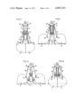
- FIGS. 1 and 2 are front elevational and part-sectional views showing the grab bucket according to this invention in the digging version, in the open and closed positions, respectively;
- FIGS. 3 and 4 are front elevational and part-sectional views showing the same grab bucket in the rehandling version, in the open and closed positions, respectively;
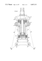
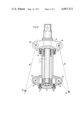
- FIGS. 5 and 6 are front elevational and part-sectional views showing on a larger scale constructional details of the grab bucket as shown in FIGS. 1 and 4, respectively, and
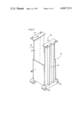
- FIG. 7 is a perspective view showing a typical form of embodiment of the detachable frame structure body.
- FIGS. 1 and 2 of the drawings showing the digging grab bucket version of the present invention.
- the grab bucket comprises in a manner already known per se a pair of symmetrical shells or scoops 1a and 1b both pivoted by means of pivot pins 3a and 3b to the lower portion of a frame structure designated in general by the reference numeral 2.
- These shells 1a and 1b are adapted to be actuated by means of a vertical cylinder-and-piston actuator housed within the frame structure 2.
- the piston rod 4 of this actuator is adapted to rotate freely but held against axial translation in relation to the frame structure 2, and comprises an upper extension through which the bucket assembly can be fastened to a hoisting or like apparatus (not shown).
- the actuator cylinder 5 is slidably mounted in the frame structure 2 and carries at its upper end diametrically opposed lugs 6a, 6b extending through relevant lateral apertures 7a and 7b respectively of frame structure 2, these lugs 6a and 6 b being connected to the shells 1a and 1b through the medium of links 8a and 8b, respectively, pivoted in turn on the one hand to said ears 6a, 6b and on the other hand to the shells 1a, 1b being designated by the reference symbols 9a and 9b, respectively.
- the frame structure 2 consists of two detachably assembled portions.
- the upper portion 10 is rigid with the piston rod 4 of the fluid-operated actuator and carries a pair of lateral pivot pins 11a and 11b.
- the lower portion 12 of said frame structure 2 is detachable and comprises apertures 7a, 7b opening at the top thereof, and also lower lugs to which the shells 1a and 1b are pivoted.
- these shells 1a and 1b are also adapted to be disassembled from the lower or body portion 12 of the frame structure 2 which will be referred to presently as the "frame structure body".
- the links 8a and 8b although constantly pivoted to the shells 1a and 1b about the relevant pivot pins 9a and 9b, can be detached from the ears 6a and 6b and pivoted to the pins 11a and 11b of upper portion 10.
- the actuator cylinder is closed at its opposite ends by a pair of interchangeable detachable covers 13 and 14.
- the lower end cover 13 is of simple circular, solid configuration and the upper gland cover 14 of annular configuration is adapted to receive the piston rod 4 of the actuator therethrough. Due to the provision of these detachable and interchangeable component elements the cylinder 5 can be turned upside down and its ears 6a and 6b can thus be disposed at will at the top or bottom thereof.
- the lower cover 13 is secured to the cylinder 5 of the actuator by means of a set of screws 15, and the top cover is secured to this cylinder 5 by means of another set of screws 16.
- This box-like body 12 comprises two solid vertical front and rear walls 17, and two vertical lateral walls 18a, 18b extending from the bottom to approximately mid-height of the body 12 to provide the corresponding lateral apertures 7a and 7b.
- the top of each solid wall 17 comprises an integral horizontal flange 19 in which holes 20 are formed to permit the passage of screws (not shown) for securing the body 12 to the upper portion 10.
- the upper central portion of this body 12, i.e. between the parallel flanges 19, is completely free.
- the frame structure body 12 remains rigidly secured to the upper portion 10 by means of the aforesaid screws, the pivot pins 11a and 11b of the upper portion 10 are not used and the shells 1a and 1b are pivoted about pivot pins 3a and 3b, but these are fixed since they are rigid with the body 12.
- Both shells 1a and 1b are detached from the lugs of the frame structure body 12 to which they are pivoted, and the upper ends of links 8a and 8b are disconnected from the corresponding ears 6a and 6b at the upper portion of actuator cylinder 5.
- the frame structure body 12 is disassembled from the upper portion 10 after releasing the screws securing said body to the upper portion.
- the lateral apertures 7a, 7b and the upper aperture of the body 12 permit of removing this body 12 notwithstanding the presence of the cylinder 5 and the ears or pivot lugs 6a, 6b thereof.
- the shells 1a and 1b are pivoted through their pivot pins 3a and 3b to the ears 6a and 6b, and the upper ends of links 8a and 8b are pivoted to the rocker 10 by means of pivot pins 11a and 11b.
- This invention is intended mainly for grab buckets for use in earthworks, but it is also applicable to grab buckets of any shape and dimensions, designed for handling coal, earth, sugarbeets, wood, etc.
- the term "shell” or “scoop” as used herein designates the two movable halves of the bucket but does not refer to any specific, well-defined shape, since the shells may consist of or comprise bowls, forks, jaws, etc.
- a particularly simple solution permitting of avoiding the steps of disassembling and turning over of cylinder 5 consists for example in providing at the bottom thereof another pair of ears similar to said ears 6a, 6b, this other pair of ears constituting additional pivot means not used in the digging bucket version but readily available for pivoting the shells 1a and 1b in the rehandling or pickup version.
Landscapes
- Engineering & Computer Science (AREA)
- Mechanical Engineering (AREA)
- Mining & Mineral Resources (AREA)
- Civil Engineering (AREA)
- General Engineering & Computer Science (AREA)
- Structural Engineering (AREA)
- Earth Drilling (AREA)
- Load-Engaging Elements For Cranes (AREA)
- Component Parts Of Construction Machinery (AREA)
Priority Applications (1)
| Application Number | Priority Date | Filing Date | Title |
|---|---|---|---|
| US05/746,990 US4059886A (en) | 1976-02-09 | 1976-12-01 | Hydraulic actuated grab bucket |
Applications Claiming Priority (2)
| Application Number | Priority Date | Filing Date | Title |
|---|---|---|---|
| FR75.04573 | 1975-02-10 | ||
| FR7504573A FR2300034A1 (fr) | 1975-02-10 | 1975-02-10 | Benne preneuse a commande hydraulique |
Related Child Applications (1)
| Application Number | Title | Priority Date | Filing Date |
|---|---|---|---|
| US05/746,990 Division US4059886A (en) | 1976-02-09 | 1976-12-01 | Hydraulic actuated grab bucket |
Publications (1)
| Publication Number | Publication Date |
|---|---|
| US4047313A true US4047313A (en) | 1977-09-13 |
Family
ID=9151207
Family Applications (1)
| Application Number | Title | Priority Date | Filing Date |
|---|---|---|---|
| US05/656,237 Expired - Lifetime US4047313A (en) | 1975-02-10 | 1976-02-09 | Convertible grab bucket |
Country Status (11)
| Country | Link |
|---|---|
| US (1) | US4047313A (ja) |
| JP (1) | JPS51105102A (ja) |
| BE (1) | BE838300A (ja) |
| BR (1) | BR7600802A (ja) |
| CA (1) | CA1050078A (ja) |
| DE (1) | DE2604952C3 (ja) |
| ES (1) | ES445024A1 (ja) |
| FR (1) | FR2300034A1 (ja) |
| GB (1) | GB1509334A (ja) |
| IT (1) | IT1053947B (ja) |
| NL (1) | NL7601091A (ja) |
Cited By (11)
| Publication number | Priority date | Publication date | Assignee | Title |
|---|---|---|---|---|
| US4124243A (en) * | 1976-05-24 | 1978-11-07 | International Harvester Company | Hydraulic actuated grab bucket |
| US4143901A (en) * | 1975-11-13 | 1979-03-13 | Nemag, B.V. | Mechanical grab |
| US4176872A (en) * | 1977-01-27 | 1979-12-04 | Nemag, B.V. | Grab or the like |
| DE3146696A1 (de) * | 1981-11-25 | 1983-06-01 | Heinz Thumm Ölhydraulische Antriebe GmbH, 7012 Fellbach | Drehvorrichtung fuer einen baggergreifer |
| EP0168711A1 (de) * | 1984-07-11 | 1986-01-22 | Erich Sennebogen | Greifvorrichtung |
| US5443294A (en) * | 1993-09-22 | 1995-08-22 | Hawco Manufacturing Co. | Single-line clamshell bucket |
| US5715614A (en) * | 1995-04-25 | 1998-02-10 | Kabushiki Kaisha Ishikatsu Exterior, Inc. | Transplant apparatus |
| US20060018238A1 (en) * | 2004-07-21 | 2006-01-26 | Trepl John A Ii | Fabrication of digital media using electron beam technology |
| US20110283571A1 (en) * | 2008-12-05 | 2011-11-24 | Serge Vuistiner | Earth moving bucket |
| US20150239713A1 (en) * | 2012-09-25 | 2015-08-27 | A Ward Attachments Limited | Hydraulic Grapple |
| US20190292746A1 (en) * | 2018-03-23 | 2019-09-26 | Cashman Dredging And Marine Contracting, Co., Llc | Slope-level-cut bucket |
Families Citing this family (4)
| Publication number | Priority date | Publication date | Assignee | Title |
|---|---|---|---|---|
| CH669002A5 (fr) * | 1986-07-18 | 1989-02-15 | Serge Vuistiner | Engin de terrassement. |
| DE29917595U1 (de) * | 1999-10-06 | 2000-11-23 | Hölscher Wasserbau GmbH & Co KG, 49733 Haren | Bohrgreifer |
| DE202015005202U1 (de) * | 2015-07-21 | 2016-10-24 | Rolf Mieger | Greifermechanik für den Greifer einer Baumaschine |
| CN221158063U (zh) | 2023-04-14 | 2024-06-18 | 法孚斯德姆斯公司 | 金属带轧机装置 |
Citations (8)
| Publication number | Priority date | Publication date | Assignee | Title |
|---|---|---|---|---|
| NL35406C (ja) * | ||||
| FR569519A (fr) * | 1923-08-07 | 1924-04-14 | Dispositif pour régler à volonté la capacité de prise des bennes preneuses | |
| GB233473A (en) * | 1924-03-03 | 1925-05-14 | Harold Richardson | Improvements relating to dashpots and like shock absorbers |
| US3258864A (en) * | 1964-03-09 | 1966-07-05 | Caterpillar Tractor Co | Motor grader blade construction |
| US3308628A (en) * | 1964-10-01 | 1967-03-14 | Comm Construction & Excavating | Cable laying attachment for a scraper vehicle |
| US3451150A (en) * | 1965-03-01 | 1969-06-24 | Auxitra Sa | Grab-bucket |
| US3606435A (en) * | 1969-10-20 | 1971-09-20 | Alman A Weber | Bore hole clam bucket |
| US3881263A (en) * | 1973-04-18 | 1975-05-06 | Poclain Sa | Angular position controller for clam-shell bucket |
Family Cites Families (1)
| Publication number | Priority date | Publication date | Assignee | Title |
|---|---|---|---|---|
| DE1236754B (de) * | 1962-09-26 | 1967-03-16 | Bodo Schlicke | Hydraulischer Motorgreifer |
-
1975
- 1975-02-10 FR FR7504573A patent/FR2300034A1/fr active Granted
-
1976
- 1976-01-22 CA CA244,043A patent/CA1050078A/en not_active Expired
- 1976-02-03 NL NL7601091A patent/NL7601091A/xx active Search and Examination
- 1976-02-05 BE BE164119A patent/BE838300A/xx unknown
- 1976-02-06 IT IT47996/76A patent/IT1053947B/it active
- 1976-02-06 GB GB4726/76A patent/GB1509334A/en not_active Expired
- 1976-02-09 US US05/656,237 patent/US4047313A/en not_active Expired - Lifetime
- 1976-02-09 BR BR7600802A patent/BR7600802A/pt unknown
- 1976-02-09 DE DE2604952A patent/DE2604952C3/de not_active Expired
- 1976-02-10 ES ES0445024A patent/ES445024A1/es not_active Expired
- 1976-02-10 JP JP51013844A patent/JPS51105102A/ja active Pending
Patent Citations (8)
| Publication number | Priority date | Publication date | Assignee | Title |
|---|---|---|---|---|
| NL35406C (ja) * | ||||
| FR569519A (fr) * | 1923-08-07 | 1924-04-14 | Dispositif pour régler à volonté la capacité de prise des bennes preneuses | |
| GB233473A (en) * | 1924-03-03 | 1925-05-14 | Harold Richardson | Improvements relating to dashpots and like shock absorbers |
| US3258864A (en) * | 1964-03-09 | 1966-07-05 | Caterpillar Tractor Co | Motor grader blade construction |
| US3308628A (en) * | 1964-10-01 | 1967-03-14 | Comm Construction & Excavating | Cable laying attachment for a scraper vehicle |
| US3451150A (en) * | 1965-03-01 | 1969-06-24 | Auxitra Sa | Grab-bucket |
| US3606435A (en) * | 1969-10-20 | 1971-09-20 | Alman A Weber | Bore hole clam bucket |
| US3881263A (en) * | 1973-04-18 | 1975-05-06 | Poclain Sa | Angular position controller for clam-shell bucket |
Non-Patent Citations (1)
| Title |
|---|
| John Deere Operator's Manual (OM-C39-1156); p. 20. * |
Cited By (14)
| Publication number | Priority date | Publication date | Assignee | Title |
|---|---|---|---|---|
| US4143901A (en) * | 1975-11-13 | 1979-03-13 | Nemag, B.V. | Mechanical grab |
| US4124243A (en) * | 1976-05-24 | 1978-11-07 | International Harvester Company | Hydraulic actuated grab bucket |
| US4176872A (en) * | 1977-01-27 | 1979-12-04 | Nemag, B.V. | Grab or the like |
| DE3146696A1 (de) * | 1981-11-25 | 1983-06-01 | Heinz Thumm Ölhydraulische Antriebe GmbH, 7012 Fellbach | Drehvorrichtung fuer einen baggergreifer |
| EP0168711A1 (de) * | 1984-07-11 | 1986-01-22 | Erich Sennebogen | Greifvorrichtung |
| US5443294A (en) * | 1993-09-22 | 1995-08-22 | Hawco Manufacturing Co. | Single-line clamshell bucket |
| US5715614A (en) * | 1995-04-25 | 1998-02-10 | Kabushiki Kaisha Ishikatsu Exterior, Inc. | Transplant apparatus |
| US20060018238A1 (en) * | 2004-07-21 | 2006-01-26 | Trepl John A Ii | Fabrication of digital media using electron beam technology |
| US20110283571A1 (en) * | 2008-12-05 | 2011-11-24 | Serge Vuistiner | Earth moving bucket |
| US8607480B2 (en) * | 2008-12-05 | 2013-12-17 | Serge Vuistiner | Earth moving bucket |
| US20150239713A1 (en) * | 2012-09-25 | 2015-08-27 | A Ward Attachments Limited | Hydraulic Grapple |
| US20190292746A1 (en) * | 2018-03-23 | 2019-09-26 | Cashman Dredging And Marine Contracting, Co., Llc | Slope-level-cut bucket |
| US10480153B2 (en) * | 2018-03-23 | 2019-11-19 | Cashman Dredging And Marine Contracting, Co., Llc | Slope-level-cut bucket |
| US10900195B2 (en) | 2018-03-23 | 2021-01-26 | Cashman Dredging And Marine Contracting, Co., Llc | Slope-level-cut bucket |
Also Published As
| Publication number | Publication date |
|---|---|
| AU1093576A (en) | 1977-08-18 |
| ES445024A1 (es) | 1977-05-16 |
| DE2604952A1 (de) | 1976-08-26 |
| FR2300034B1 (ja) | 1978-02-03 |
| CA1050078A (en) | 1979-03-06 |
| JPS51105102A (ja) | 1976-09-17 |
| IT1053947B (it) | 1981-10-10 |
| DE2604952C3 (de) | 1981-05-14 |
| BR7600802A (pt) | 1976-08-31 |
| GB1509334A (en) | 1978-05-04 |
| FR2300034A1 (fr) | 1976-09-03 |
| DE2604952B2 (de) | 1980-09-04 |
| BE838300A (fr) | 1976-05-28 |
| NL7601091A (nl) | 1976-08-12 |
Similar Documents
| Publication | Publication Date | Title |
|---|---|---|
| US4047313A (en) | Convertible grab bucket | |
| US3767070A (en) | Lifting and excavating apparatus | |
| US4283866A (en) | Convertible bucket attachment capable of excavation and clasping | |
| US4643631A (en) | Quick coupling and release mechanism for buckets | |
| US4845867A (en) | Triple-purpose attachment | |
| US3209474A (en) | Tractor loader with pivotal scoop portion | |
| US2927706A (en) | Hydraulically-operated dipper | |
| US2828038A (en) | Excavating apparatus | |
| US4059886A (en) | Hydraulic actuated grab bucket | |
| JPH05239846A (ja) | 掘削機用ブームアーム連結器 | |
| WO1983001473A1 (en) | Releasable bucket and other tool connection for backhoe | |
| CN107002380B (zh) | 作业用行走机主体中的前附件 | |
| US6126216A (en) | Bucket attachment for log grapple | |
| KR101825483B1 (ko) | 관형 피봇을 갖는 중하중 그래플 | |
| US3997068A (en) | Assembly for attachment to excavators | |
| US3872986A (en) | Self-cleaning bucket arrangement for an excavator | |
| US3148465A (en) | Tractor loaded with two-piece bucket | |
| US5940996A (en) | Material ejecting loader bucket | |
| GB2126982A (en) | Hydraulic excavator equipment | |
| US2719641A (en) | Earth moving apparatus or the like | |
| JPH01151622A (ja) | スコップを持つ掘削バケット | |
| US5176491A (en) | Overcenter backhoe apparatus | |
| US4735547A (en) | Backhoe mounting | |
| US3129832A (en) | Multiple-purpose power shovel | |
| US3517960A (en) | Hydraulic actuated clamshell bucket attachment for stick clam excavators or the like |
Legal Events
| Date | Code | Title | Description |
|---|---|---|---|
| AS | Assignment |
Owner name: NAVISTAR INTERNATIONAL CORPORATION Free format text: CHANGE OF NAME;ASSIGNOR:INTERNATIONAL HARVESTER COMPANY;REEL/FRAME:004546/0650 Effective date: 19860220 Owner name: NAVISTAR INTERNATIONAL CORPORATION, ILLINOIS Free format text: CHANGE OF NAME;ASSIGNOR:INTERNATIONAL HARVESTER COMPANY;REEL/FRAME:004546/0650 Effective date: 19860220 |
|
| AS | Assignment |
Owner name: NAVISTAR INTERNATIONAL CORPORATION A CORP. OF DE, Free format text: MERGER;ASSIGNOR:NAVISTAR INTERNATIONAL TRANSPORTATION CORP. (MERGED);REEL/FRAME:005195/0610 Effective date: 19870317 |